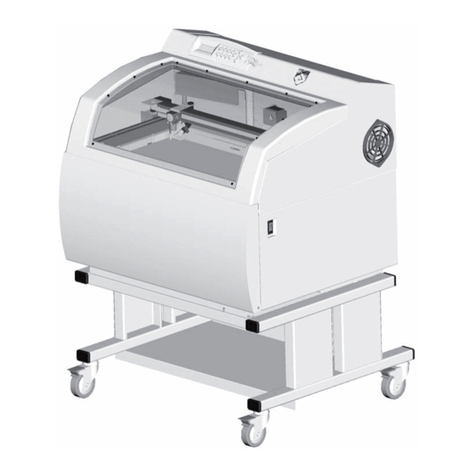
GRAVOGRAPH IM4 User manual

Before installing and using this ma-
chine, you must read this user
guide carefully. Keep it in a safe
place, in case you need to refer to
it later.
D9090 701 - 01.2003 - ENG - (UPDATED EDITION NUMBER: 1)
(Please read carefully before use)
User manual
I 4 machine
First contact

IM4 machi e . 2
First contact
Gravograph reserves the right to modify the information contained in this document without notice.
TYPE OF ACHINE : I 4
ANUFACTURER : GRAVOGRAPH INDUSTRIE INTERNATIONAL
BP 15 - Z.I. - 10600 LA CHAPELLE SAINT LUC - FRANCE
Importer's address

First contact
IM4 machi e . 3
Summary
Information about regulations ............................................................ 4
Co formity sta dards ...................................................................................................................... 4
Electrical security ........................................................................................................................... 4
Presentation ....................................................................................... 5
Co tra-i dicatio s .......................................................................................................................... 5
Stages of u packi g ....................................................................................................................... 7
U packi g - Co te ts of package ...................................................................................................... 7
Description ......................................................................................... 9
Fro t view of the machi e ............................................................................................................... 9
Rear view of the machi e .............................................................................................................. 10
Installing .......................................................................................... 11
Physical i stallatio advice ............................................................................................................. 11
Electric i stallatio advice .............................................................................................................. 13
Electrical co ectio s of the machi e .............................................................................................. 13
Setti g up tra smissio betwee the IM4 a d a PC type computer ...................................................... 14
Switchi g the machi e o .............................................................................................................. 16
Problems ..................................................................................................................................... 16
Switchi g the machi e off ............................................................................................................. 16
Mecha ical block .......................................................................................................................... 16
Switchi g o agai ....................................................................................................................... 16
I stalli g the e gravi g software i Wi dows ................................................................................... 17
From the transfer to the engraving ................................................... 18
Positio i g the plate o to the vice .................................................................................................. 18
Adjusti g the spi dle with automatic ZRef. ......................................................................................21
Starti g to e grave ...................................................................................................................... 23
General maintenance ........................................................................ 24
Cha gi g the fuses ....................................................................................................................... 24
Technical characteristics ................................................................... 25
Physical characteristics .................................................................................................................. 25
Electrical characteristics ................................................................................................................ 26
Software characteristics ................................................................................................................ 26

IM4 machi e . 4
First contact
Information about regulations
Conformity standards
This hardware was desig ed a d built i co formity with the releva t EC marki g a d EEC directives :
• "Machi e security" Directive 98/37/EEC (22/06/98).
• "Electromag etic compatibility" Directive 89/336/EEC (03/05/89) (modified).
• "Low voltage" Directive 73/23/EEC (modified).
The modification or transformation of this equipment, the adaptation and installation
of accessories not recommended by GRAVOGRAPH, the installation of this equipment
in a manufacturing process, the piloting by a robot, the connection to an external
automaton, modify the characteristics of this material and can make it not compliant
with the European Directives it is subjected.
These modifications voids the responsibility of the manufacturer.
In this case, the person who fits the machine and the equipment is responsible for the
EC compliance of the final work station.
Electrical security
This hardware is i co formity with the orms EN 60204-1 a d EN 60950.
The differe t fuses of the machi e comply with the IEC 127-2 orm (I ter atio al Electric Committee).
The differe t security levels the i put/output a swer are i dicated for each co ector i the chapter "Rear view of the
machi e". Two security levels are possible :
- Da gerous voltage (power supply, accessories, plugs ...).
- Very low security voltage.
achine security
This hardware is i co formity with the orm EN 292-1 a d EN 292-2.
Electromagnetic compatibility
This hardware is i co formity with electromag etic compatibility orms:
• EN 50081-1 (emissio i reside tial, commercial, a d light i dustrial e viro me t)
• EN 61000-6-2 (immu ity i i dustrial e viro me t)
All the cables used with this hardware must be i co formity with the electro ic compatibility sta dards, orm
EN 55022 - class B.
Electrical security
This material is «class 1». The mains plug UST always be connected to a neutral
socket and comply with the regulations in force in the country of installation. If you
do not have a plug of this type, have one installed by an approved electrician. Under
no circumstances should you depart from this instruction.
The ma ufacturer bears o respo sibility towards a y user where alteratio s have bee carried out co trary to the
ma ufacturer's specificatio s, otably with respect to electrical/electro ic eleme ts.
Any operation, other than those mentioned here, must only be carried out by an
approved Gravograph technician.
Do not take the machine apart to repair or clean it : this will void your guarantee.
First contact
IM4 machi e . 5
• Do ot spill a y liquids o to the machi e (dri ks, clea i g fluids…) u less whe recomme ded by GRAVOGRAPH
(example: lubricatio ).
• The machi e should ever be used with a ythi g other tha Gravograph accessories a d tools.
• O ly use e gravi g tools (cutters, oses...) as directed i the "CUTTERS CATALOGUE".
• Never hold the material to be e graved i your ha ds. O ly use the GRAVOGRAPH clampi g systems desig ed for your
machi e.
• Make sure that the material is well clamped before starti g to e grave.
• Duri g e gravi g, do ot use this machi e without a ose (depth regulati g ose or vacuum ose) i order to avoid
projectio s of swarf.
• Do ot take the e gravi g material out of the machi e duri g e gravi g.
• If the e gravi g must be stopped, use the fu ctio key provided for this purpose o the co trol pa el of the machi e.
To avoid any risks of being crushed by the machine during engraving, do not stand near
the tools (the travel area of the tool is 4"3/4 x 3"5/32 inches (120 x 80 mm)).
Do not lean over the spindle holder.
This sign shown on the tool-holder of the machine shows the danger
caused by the rotating spindle during engraving (risks of getting burnt
or cut).
Presentation
The machine must never be handled without an adult present. Keep the machine,
wires and cables out of children's reach.
Contra-indications
This machine is only designed for light engraving purposes and must never be used for
other applications.
To use this machine, you are advised to wear protectives glasses against the chip
ejections.
Never use this machine for sawing or drilling.
Do not use this machine for working with wood.
Do not use this machine in explosive environment.
This machine is only designed for one user. Do not let several people use the machine
simultaneously.
• If the machi e is ot to be used for a lo g period, u plug the electricity supply a d cover the machi e (packagi g, cover,
lid...)
• Do ot move the e gravi g head by ha d (pict. 1) u less mecha ical block of the machi e as described i the paragraph
"Mecha ical block" of this ma ual's "I stalli g" chapter.

IM4 machi e . 6
First contact

First contact
IM4 machi e . 7
Stages of unpacking
Before opening the cardboard box, check that it is the right way up.
After ope i g the box (pict. 1):
1. Take out the manual.
2. Take out the toolbox and the cable.
Never lift or move this machine by its arm (pict. 2).
3. Take out the machine.
Shows where you should put your ha ds (pict. 2).
ake sure that no components are missing from the packaging. If any part has been
forgotten please get in touch with your GRAVOGRAPH dealer.
Keep all the packagi g materials so that you ca move your machi e i total safety.
This packagi g is i co formity with Europea recycli g sta dards.
Unpacking - Contents of package
Check the condition of the packaging when you receive it. If there are any signs of
damage, inform the carrier and your GRAVOGRAPH dealer immediately by recorded
delivery, specifying the exact nature of the problem.
Contents of package
(pict. 3)
A. A IM4 machi e (a depth-regulati g ose a d a pair of jigs mou ted o the machi e)
C. A ma ual to be placed i to a folder, with a label to stick alo g the spi e of the folder
D. A tool box
E. A power cable
F. A serial co ectio cable (RS232)
Contents of tool box
(pict. 4)
D1. a short alle key
D2. a brush
D3. two fuses T 2 A H - 250V *
T 2 A H - 250V * = These fuses are temporized, with a high breaking capacity and
comply with the IEC 127-2 norm.

IM4 machine . 8
First contact

First contact
IM4 machine . 9
Description
The IM4 machine is an engraving machine.
It has a control panel connecting the software which is in the machine.
Files to be engraved are transferred from the computer to the machine by the intermediary of a cable which is plugged into the serial port
of the IM4 machine.
The actual engraving process is controlled by the spindle.
The object to be engraved is held by a vice (as standard) or by any other system recommended by GRAVOGRAPH (consult your
GRAVOGRAPH dealer for more information on systems available).
The I 4 machine has a maximum engraving surface area of
4"3/4 x 3"
5/32 inches
(
120 x 80 mm).
Front view of the machine
(pict. 1)
H. Base
J. Ensemble tool holder
K. Vice with pair of jaws
L. Main stop button
B. Control panel (9-key control keyboard)
Tool holder
(pict. 2)
J1. Cutter
J2. Cutter button
J3. Pressure knurl on spindle
J6. Scaled knob
J7. Nose nut
J8. Index finger
Vice
The vice allows to hold odd shaped and small objects to be engraved (small volume).
To mount a pair of jigs onto the vice (pict. 3):
1. Open the jaws by turning the tightening knob anti-clockwise.
Open them far enough so as to mount the jaws easily.
2. Push the jigs firmly onto the pins of the jaws .

IM4 machine . 10
First contact
Rear view of the machine
Each connection responds to one of the following security levels :
- Dangerous voltage.
- Very low security level.
N. Connection socket - engraving table (diagram 1)
N1 - Li ks the e gravi g table with the electro ics box - Very low security level
N2 - Mai s supply plug with 2 fuses drawer T 2 A H - 250V * - Dangerous voltage
T 2 A H - 250V * = These fuses are temporized, with a high breaking capacity and
comply with the IEC 127-2 norm.
N3 - Serial port - Very low security level
N4 - Do not use
The machine must always be switched off before connecting or disconnecting a cable
as indicated on label displayed on the back of the machine :
To avoid any risk of electrical shock, always disconnect the power cord before
removing this cover (label ).
2 A T

First contact
IM4 machine . 11
Installing
Before carrying out the following operations, make sure the machine is switched off
and unplugged, switch (L) to position 0 (pict. 2).
Physical installation advice
• Put the Gravograph machine onto a stable flat, clean surface with mini. sizes of 25"5/8 x 11"7/8 inches (650 x 300 mm).
Make sure the back of the machine is well-ventilated, do not put it too close to anything (wall, other machines etc) (pict. 2).
• Clear the work surface so that you can
- easily and quickly access all external parts of the machine,
- quickly access, in case of necessity, the main stop button (L) on the machine (pict. 2),
- make sure that all moving parts of the machine have enough room to move freely,
- avoid any accidental unplugging of the cables.
The machine's power supply cable being used as a sectionning device, it must be easily
accessible and the wall plug must be installed near the machine and must also be easily
accessible.
The connectors screws must be very tight to avoid accidental disconnection of the
cables while the machine is turned on as this could permanently damage the electronic
cards (label ).
• Protect Gravograph equipment against:
- Moisture (rain, snow, condensation…),
- Heat (direct sunlight, heating…),
- Brusque temperature changes,
- Dust (exhaust pipe),
-Liquid splashes,spillagesonthe electronicrack,cablesand connections,andanyother partofthemachine; unlessrecommended
by GRAVOGRAPH (ex. : lubrication),
- Vibrations,
- Electric or electronic radiation.

IM4 machine . 12
First contact
2 A T

First contact
IM4 machine . 13
Electric installation advice
This material is «class 1». The mains plug UST always be connected to a neutral
socket and comply with the regulations in force in the country of installation. If you
do not have a plug of this type, have one installed by an approved electrician. Under
no circumstances should you depart from this instruction.
In order to avoid outside interference, the user is advised to carry out the following points.
• Plug the Gravograph machine into a mains line, avoiding having several machines on the same line (several plugs on the same line or
using a multi-plug).
Exception : If other things are connected to the machine (such as a computer and the I 4
machine), the machines should be connected to the same mains line.
• Avoid using the same line to supply inductive or capacitive machines as well as the Gravograph machine (motors, electrosluices,
chargers...).
• Avoid using a manual or automatic commutator on the same mains line as the Gravograph machine (relay, temporiser, programmer,
automatic circuit interrupter, automatic interrupter...).
• CheckthatmachinessurroundingyourGravographmachineareinconformitytothenormsofradioelectricperturbationemissions(consult
the technical leaflet of each machine). If they are not in conformity, place them as far away as possible from the Gravograph machine.
• Only use Gravograph accessories (Gravograph relay box, etc ...).
The machine must always be switched off before connecting or disconnecting a cable
(label ).
Electrical connections of the machine
Stand behind the machine (diagram 1).
1. Plug in the electric cable , first to the engraving table, then to the mains supply.
To cut off the mains supply to your machine in the case of severe problems, unplug the
mains cable or swith off the machine with the main stop button at the side of
the engraving table (pict. 2). ake sure that you can reach them easily.

IM4 machi e . 14
First contact
125
1
9
1
25
1
9
1
9
1
25
2 A T
2 A T

First contact
IM4 machi e . 15
Setting up transmission between the I 4 and a PC type computer
The computer and the I 4 machine must be switched OFF.
PC computers and the WINDOWS® graphic environment being very widespread
throughout the world, we have based ourselves on these products to define the
installation and use procedures of the I 4.
If you do 't have equipme t which is compatible a d you e cou ter some problems of i stallatio or use, co tact your
Gravograph age t.
Connection cables
• Use Gravograph co ectio cables (co sult your Gravograph distributor for the products available).
These cables are adapted for the machi es to which they will be co ected.
They must be i co formity with the electromag etic compatibility sta dards, orm EN 55022 - class B a d protect from
exter al electric "attacks" (co form to the orms of immu ity a d CEM susceptibility).
• Do ot use cables which are too lo g. Keep the machi es as close as possible a d use a short a cable as possible.
• Separate the mai s cable a d the tra smissio cable (avoid co ecti g the tra smissio a d mai s cables to the same
socket, etc ...).
Follow the connection procedure depending on the transmission cable supplied with the
I 4.
The machi e is delivered with the followi g cables :
• RS232 serial cable (bi-directio al)
Optio al:
• 25-9 poi t adaptor for serial cable
PC/I 4 connection using the serial port
1. Plug the serial cable into the serial port of machine (pict. 1).
This is a 9-pi co ector.
2. Plug the serial cable into the serial port of the PC.
Refer to the i stallatio ma ual of the computer for the serial port.
PC computer ca have two types of serial port :
• 9-poi t serial port (diagram 2, transmission example diagram 6)
• 25-poi t serial port (diagram 3)
If you use a 25-point serial port, connect the 25-9 point adaptor (diagram 4) onto the serial cable
before plugging it into the computer (diagram 5).
The connectors screws must be very tight to avoid accidental disconnection of the
cables while the machine is turned on as this could permanently damage the electronic
cards.

IM4 machi e . 16
First contact
Switching the machine on
Switch on the machine (main stop button (L) to position I).
Whe switched o the red light of the mai stop butto (L) will come o .
The machi e will the emit a "beep".
Leave the machine plugged in even if it is not in constant use.
Problems
If o e of the operatio a sig s is abse t, check the followi g poi ts :
• Are the twoo e ds of the mai s cable correctly co ected ?
• Is the mai s plug co ected ? Is it live ?
If the machine does not come on, before calling a technician, please check power
connections to the mains socket and also the fuses (see "Changing the fuses").
Switching the machine off
Switch the main stop button (L) to position 0.
Switch off the machi e for the followi g reaso s :
- if you are leavi g the workstatio (e d of the day, for example),
- physical damage (fall, fire, liquids comi g i to machi e…),
- mecha ical/electrical/electro ic faults, leadi g to a possible breakdow ,
- i case of major problem or mecha ical block of the machi e,
- to reboot,
- for exter al clea i g.
echanical block
I the followi g cases :
- da ger for the operator,
- block o the support to be e graved,
- block o a object placed i the work area,
1. Cut the power supply by switching the main stop button (L) to position 0.
2. Free the tool, without switching the machine on, by manually and slowly moving the tool holder
as required.
3. Only switch the machine back on after ensuring that the tool's moving area is totally clear.
Switching on again
If the machi e or the programme which ru s it crashes you may have to reboot the machi e.
If this happe s, switch the machi e off. Wait 30 seco ds a d switch it o agai .
You must wait for 30 seconds. This time allows any electric shock to the machine,
possibly damaging the power supply, to be avoided.

First contact
IM4 machi e . 17
Installing the engraving software in Windows
1. Check that your computer has the minimum required configuration:
PC computer Co figuratio
Microprocessor Pe tium III
Freque cy 800 Mhz
Ra dom Access Memory (RAM) 128 MB
1 i ter al hard disk 10GB with 100 MB free
1 i ter al CD-ROM drive x24
1 i ter al 3"1/2 disk floppy drive
1 mouse Wi dows compatible
1 keyboard exte ded (105 keys)
LPT parallel port 1
COM serial port 1
1 graphic board 32000 colors, 16 bits
1 color SVGA mo itor 15", 800x600 DPI resolutio
Software e viro me t Wi dows XP
I ter et Explorer 5 (or more)
Acrobat Reader 5 (or more)
Microsoft Word 2000 (or more)
Wi dows Media Player
Arial, Microsoft Sa s Serif, Verda a fo ts
2. Insert the CD-RO in the drive and close the drive.
3. Wait until the Installation panel is displayed.
Double-click the driver if the panel is not opening.
4. The installation automatically runs: the Progression bar and panel indicate the course of
operations.
5. Click to quit the Installation panel.
6. Run GravoStyleQuick: click its icon on the Desktop.
7. To engrave a first plate, run the Tutorial.

IM4 machi e . 18
First contact
765432101234567
Alex BOREL
100 mm
765432101234567
765432101234567

First contact
IM4 machi e . 19
From the transfer to the engraving
Transfer procedure
You have just created a compositio with your e gravi g software.
1. Switch on the I 4 machine and wait a few seconds.
2. Check that the automatic ZRef. function is selected in your engraving software.
3. Transfer the composition from the engraving software to the machine (refer to the "Transferring
the composition for engraving" topic in the contexthelp of your engraving software).
Positioning the plate onto the vice
4. Choose the jigs recommended on the Engraving screen of the engraving software (consult your
GRAVOGRAPH dealer for more information on the various jigs available).
The le gth of the plate should ot exceed the le gth of the jigs (diagram 1).
5. Choose adequate side of the jigs according to the thickness of the plate.
The plate should be slightly higher tha the jigs (diagram 2) to avoid that the regulati g ose touches the jigs.
6. ark the middle of the plate.
7. Centre the plate so that the centre mark is lined up with the 0 on the jig (diagram 3).
8. Using the tightening knob, tighten the plate so that it cannot move during engraving.
If the plate is correctly tighte ed, oise a d vibratio s are reduced to a mi imum whe the machi e is e gravi g.
Check that the object is tightened correctly to ensure that it is not ejected during
engraving.

IM4 machi e . 20
First contact
5
0
5
0
2 mm
2 mm
Table of contents
Other GRAVOGRAPH Printer manuals

GRAVOGRAPH
GRAVOGRAPH M20 BEAUTY CUBE Operating instructions

GRAVOGRAPH
GRAVOGRAPH L-Solution 700 User manual

GRAVOGRAPH
GRAVOGRAPH LS900 Fibre Operating instructions

GRAVOGRAPH
GRAVOGRAPH IS400 User manual

GRAVOGRAPH
GRAVOGRAPH IS900 User manual

GRAVOGRAPH
GRAVOGRAPH IS200 User manual

GRAVOGRAPH
GRAVOGRAPH M10 JEWEL User manual

GRAVOGRAPH
GRAVOGRAPH IS200 Operating instructions