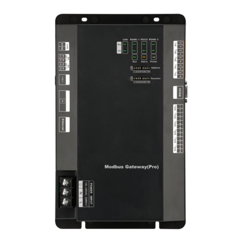
Gree GMV BACnet Operating manual

GMV BACnet Gateway
Technical Service Manual

Safety Notice
Dear customer,
Please read this manual carefully prior to installation and operation and strictly observe all
installation and operation instructions covered in the manual.
Special attentions shall be paid to the following marks:
WARNING.This mark indicates operation, which if improperly performed, might lead to
the death or serious injury of the users.
CAUTION.This mark indicates operation, which if improperly performed, might
possibly result in damage to the device.
WARNING
1. Installation shall be performed by the qualified personnel; otherwise it would result in a fire
hazard or electric shock.
2. Do not place the plug of the power supply into the socket before it is dried and cleaned.
3. Cut off the power supply before touching the electric element.
4. Do not touch this device with wet hands; otherwise it would result in electric shock.
5. Do use the power cable specified in this manual; otherwise it would result in a fire hazard.
6. When the power cable is reversely connected or the power supply is beyond the rated
range, it would result in a fire hazard or even damages to this device.
7. Do install this device inside the electric control cabinet which is located indoor and then is
locked.
8. Do install this device where it will not be subject to the electromagnetic interference or
heavy dust.
CAUTION
1. Be sure the specified adaptor is used; otherwise this device would work improperly or even
be damaged.
2. Be sure this device is setup in place; otherwise it would result in communication fault.
3. Be sure the communication line is connected to the correct interface; otherwise it would
result in communication fault.
4.After connection, lines should be protected with insulating tape to avoid oxidation and short
circuits.
5. Normal working conditions for BACnet gateway:①Temperature: -20~+70℃,②Humidity:
less than 85%; ③Location: install this product in the electric control cabinet, not subject to direct
sunlight, rain and snow etc.

Contents
PART I INSTALLATION..............................................................................................................................1
1. SYSTEMOVERVIEW..................................................................................................................... 1
2.ASSEMBLYINTRODUCTION........................................................................................................ 2
2.1ASSEMBLYLIST............................................................................................................................ 2
2.1.1 SAFETY REQUIREMENT FOR ENGINEERING INSTALLATION CONSTRUCTION .... 2
2.2 GATEWAY ME30-24/D4(B)........................................................................................................... 2
2.2.1 FUNCTION INTRODUCTION................................................................................................... 2
2.2.2 APPEARANCE PICTURE......................................................................................................... 3
2.2.3 ASSEMBLY.................................................................................................................................. 3
2.2.4 INTERFACE ................................................................................................................................ 4
3.EQUIPMENT INSTALLATION......................................................................................................... 5
3.1 PRODUCT SIZEAND SPATIALSIZE FOR ELECTRIC CONTROLCABINET
INSTALLATION..................................................................................................................................... 5
3.1.1 PRODUCT SIZE......................................................................................................................... 5
3.1.2 SPATIAL SIZE FOR ELECTRIC CONTROL CABINET INSTALLATION........................... 5
3.2 COMMUNICATION CONNECTION ............................................................................................ 6
3.2.1 MATERIAL SELECTION FOR COMMUNICATION LINE..................................................... 6
3.2.2 COMMUNICATION CONNECTION METHOD ...................................................................... 6
3.2.3 COMMUNICATION CONNECTION STEP............................................................................. 7
PART II DEBUG OPERATION.................................................................................................................9
1. HARDWARE DEBUG ...................................................................................................................... 9
1.1 DIAL-UPSETTING......................................................................................................................... 9
1.2 LED DISPLAY............................................................................................................................... 10
1.3 DI/DO..............................................................................................................................................11
2.COMMUNICATION DEBUG.......................................................................................................... 12
2.1 COMMUNICATION DEBUG WITHAIR CONDITIONING EQUIPMENT.............................. 12
2.1.1 BACnet GATEWAY CONFIGURATION................................................................................. 13
2.2 COMMUNICATION DEBUG WITH BMS SYSTEM EQUIPMENT......................................... 13
2.3 EXCEPTION HANDLING............................................................................................................ 14
PART III MAINTENANCE....................................................................................................................... 16
1.COMMON TROUBLESHOOTING OF BMS SYSTEM............................................................... 16

GMV BACnet Gateway Technical Service Manual
1
PART I INSTALLATION
1.SYSTEM OVERVIEW
GMV BACnet gateway plays a role in connecting intranet of air conditioners (CANbus) and
BMS, providing standard BACnet/IP building interface and realizing real time monitor of BMS to
unit condition. Through BACnet gateway, it can conduct data collection, monitor and control to the
operation status of GMV air conditioner in long distance and timely give an alarm once malfunction
occur. The air conditioning maintenance staffs do not need to conduct setting and management to
every unit on site in person, instead, they can check the operation status, start and operation, and
have temperature setting of building air conditioning system by just sitting in front of the computer,
which not only greatly enhances work efficiency, but also decreases human cost and lower
management cost.

GMV BACnet Gateway Technical Service Manual
2
Internet topological graph specification
CAN2 bus internet: the red wire is CAN2 bus, which is consist of BACnet gateway and main
control ODU of the system. One CAN2 internet can be connected to maximum 16 systems and
255 IDUs.
CAN1 bus internet: the black wire is CAN1 bus, which is consist of BACnet gateway and all
IDUs and ODUs of the system. One CAN1 internet can be connected to maximum 80 IDUs.
System: one system is consisting of a set of ODU (a set of ODU is a module which is consist
of 1-4 modules, namely 1-4 ODUs) and the affiliated IDUs.
The admissible unit quantity for BACnet gateway: one BACnet gateway can be connected
to maximum 16 systems and 255 IDUs.
Note: L1 in the fig is the standard network cable, L2 and L3 is the twisted-pair.
2. ASSEMBLY INTRODUCTION
2.1 ASSEMBLY LIST
2.1.1 SAFETY REQUIREMENT FOR ENGINEERING INSTALLATION
CONSTRUCTION
Name
Model
Material
code
Supply
range
Remark
BACnet
gateway kit
Gateway
component
ME30-24/D4(B)
MC200013
00
Standard
configura
tion
It can connect to BMS system.
Protocol interface: CAN and
BACnet protocol
Hardware interface: CAN port
and Ethernet port.
Main component: BACnet
gateway and specification
Power cord
--
--
Free
configura
tion
0.5mm2--1mm2
Communication
cord
--
--
Free
configura
tion
2
0.75mm2
2.2 GATEWAY ME30-24/D4(B)
2.2.1 FUNCTION INTRODUCTION
GMV BACnet gateway kit ME30-24/D4(B) is intended to realize the data exchange between
the air conditioning unit and BAS system, and providing standard BACnet/IP building interface and
10 I/Os (five inputs are DI1, DI2, DI3, DI4, DI5 and five outputs are DO1, DO2, DO3, DO4, DO5).
DI1 is the fire alarm interface. The status of other I/Os are mapped to the specific objects of the
BACnet/IP bus and are defined by the user. This gateway applys to the GMV using CAN protocol.

GMV BACnet Gateway Technical Service Manual
3
2.2.2 APPEARANCE PICTURE
2.2.3 ASSEMBLY
GMV gateway ME30-24/D4(B) includes the following components:
BACnet gateway
1 set
Specification
1 set
BACnet Gateway
Specification

GMV BACnet Gateway Technical Service Manual
4
2.2.4 INTERFACE
1)Diagram of interface
CAN communication
interface connected
to the AC unit
Power input
Communication interface
of ethernet, used for
remote control
monitoring communication
Reserve 5-way
input IO port
Reserve 5-way
output IO port
2)Power
The input power is 100VAC-240VAC,50/60Hz.
WARNING! The ground protection of power input port must be connected; otherwise it
might be dangerous; besides, when the gateway is energized, don’t touch the power input.
Note: the power cord shall be fixed with bonding clamp in the kit, as shown in the fig.
3)Communication interface
CAB communication interface: connect it to the AC unit through the 2-core communication
line to realize the communication between BACnet gateway and theAC which adopts CAN
protocol.
RS485-1 communication interface: this device will not use this communication interface
temporarily.
RS485-2 communication interface: this device will not use this communication interface
temporarily.
USB and SD card interface: this device will not use this interface temporarily.
Ethernet interface: realize communication through network cable and BMS.

GMV BACnet Gateway Technical Service Manual
5
3.EQUIPMENT INSTALLATION
3.1 PRODUCT SIZEAND SPATIAL SIZE FOR ELECTRIC
CONTROL CABINET INSTALLATION
3.1.1 PRODUCT SIZE
296mm
177mm
56mm
98.5mm
L ×W ×H:296×177×56(mm)
3.1.2 SPATIAL SIZE FOR ELECTRIC CONTROL CABINET
INSTALLATION
BACnet gateway shall be installed in electric control cabinet; the front of gateway shall be
hung upward and fixed with 4 screws. See the following fig (for reference).
Warning! Power cord and communication line of BACnet gateway must conduct routing
separately(the distance shall be over 15cm); otherwise, it might lead to BACnet
gateway communication malfunction!
The thin dotted line is communication line and the thick dotted line is the heavy current wire,

GMV BACnet Gateway Technical Service Manual
6
the routing shown is for reference only.
3.2 COMMUNICATION CONNECTION
BACnet gateway communication system includes:
(1)The communication between BACnet gateway and BMS;
(2)The communication between BACnet gateway andAC units.
3.2.1 MATERIAL SELECTION FOR COMMUNICATION LINE
(1)Model selection of BACnet gateway and BMS communication line shall use standard
Ethernet communication line, the length of network cable between gateway and router (computer,
switchboard, etc.) shall not exceed 80m;
(2)Communication line model selection for BACnet gateway andAC unit
Wire type
Communication
line between
gateway and
AC units(m)
Wire diameter(mm2)
Wire standard
Remark
Light-weight/normal
PVC jacket twisted
copper wire(RVV)
L
500
2
0.75
GB/T
5023.5-2008
Total communication
length shall not exceed
500m
3.2.2 COMMUNICATION CONNECTION METHOD
(1)Communication connection between BACnet gateway and BMS.
(2)Communication connection between BACnet gateway andAC units (n is the quantity of
ODU system, n ≤ 16);
Notice! All communication connection lines under BACnet gateway must be in series
connection, star connection shall not be adopted.

GMV BACnet Gateway Technical Service Manual
7
3.2.3 COMMUNICATION CONNECTION STEP
(1)Communication line connection between BACnet gateway and PC;
Connection diagram between BACnet gateway and PC use side:
1)Adopt cross connection network cable, BACnet gateway shall directly connect to PC.
2)Adopt parallel network cable, BACnet gateway shall go through router to connect to PC.

GMV BACnet Gateway Technical Service Manual
8
(3)Communication line connection between BACnet gateway andAC units:
When gateway is connected to main control unit of ODU, ODU with the address dial-up of 0
must be connected.

GMV BACnet Gateway Technical Service Manual
9
PART II DEBUG OPERATION
1. HARDWARE DEBUG
1.1 DIAL-UP SETTING
Notice! Before using this device, please conduct dial-up setting first; otherwise the unit will
not function normally!
Gateway dial-up setting area is consisting of address dial-up machine and function dial-up
machine.
1)Diagram of dial-up machine
HSBLSB
1 65432 7 8
0
1
is the location for dial-up button
Dial-up value in
this location is 0 Dial-up value in
this location is 1
2)8 address dial-up buttons——gateway reset configuration
If information such as BACnet gateway IP address configured on the webpage, subnet mask,
default gateway, gateway name and gateway ID are mistaken, and the webpage cannot be visited,
dial up the 8 address dial-up buttons to “1”, after all indicating lights (except power indicating light)
are blinking, reset the dial-up button and restart the gateway, then the default information in
gateway manufacture setting can be restored.
HSBLSB
1 65432 7 8
0
1
Is the location for dial-up button.
3)No.8 functional dial-up machine——matched resistance setting of CAN bus

GMV BACnet Gateway Technical Service Manual
10
Notice!
Main control ODU or gateway at the top/end of CAN bus must be with matched resistance;
otherwise the communication might be wrong!
※CAN bus: specific meaning shall refer to the specification Internet topological graph.※
The No.8 dial-up button in function dial-up machine shall be used in the setting in the matched
resistance of CAN bus in this gateway.
When the gateway is at the top/end of CAN bus, the gateway shall be with the matched
resistance, then dial the No.8 function dial-up machine to 0;
When the gateway is not at the top/end of CAN bus, the gateway is not with the matched
resistance, then dial it to 1.
main control unit of
ODU system 2 main control unit of
ODU system n
main control unit of
ODU system 1
……
set to be with the
matched resistance
set to be with the
matched resistance set not to be with the
matched resistance
CAN bus
main control unit
of ODU system 2 main control unit
of ODU system n
main control unit
of ODU system 1
……
set to be with the
matched resistance
set to be with the
matched resistance
set not to be with the
matched resistance
set not to be with
the matched
resistance
CAN bus
n stands for the quantity of ODU system, n≤16.
Dial-up setting graph for the matched resistance:
8
with the
matched
resistance
not with
the
matched
resistance
8
is the location for dial-up button
function
1 65432 7 8
0
1
0
1
1.2 LED DISPLAY
The above LED indicator is mainly consisting of two parts: status indicator (run, alarm, power)
and communication indicator (CAN, RS485, RS2332). The following table is the working status of
each indicator.

GMV BACnet Gateway Technical Service Manual
11
CAN
RX
When receiving the data of equipment (eg. AC unit) which connects to BACnet
gateway, it blinks.
CAN
TX
When transmitting data to the equipment (eg. AC unit) which connects to
BACnet gateway, it blinks.
RS485-1
RX
This device does not use this LED indicator.
RS485-1
TX
This device does not use this LED indicator.
RS232
RX
This device does not use this LED indicator.
RS232
TX
This device does not use this LED indicator.
RS485-2
RX
This device does not use this LED indicator.
RS485-2
TX
This device does not use this LED indicator.
Power
When power supply of BACnet gateway is normal, it is on.
Run
When BACnet gateway is running normally, it blinks.
Alarm
This device does not use this LED indicator.
1.3 DI/DO
So far, this gateway supports 5 DIs (digital input) and 5 Dos (digital output), DO6 is reserved.
DI1...DI5
Digital input 0/1 digital signal (binary system), apply to active input.
DI 1: in CAN2 network, fire alarm signal, connect “1” to the power of 12V, input fire alarm
signal “1” in DI 1 port, then BACnet gateway will give out control, all units stop operation
immediately; disconnect “1” or connect to “0”, input signal “0” in DI 1 port, resume operation of
all ODUs.
In CAN1 network, fire alarm signal, connect “1” to the power of 12V, input fire alarm
signal “1” in DI 1 port, then BACnet gateway will give out control, all units stop operation
immediately; disconnect “1” or connect to “0”, input signal “0” in DI 1 port, resume operation of
IDUs manually.
DI 2...DI 5:Defined by the user.
DO1...DO5
Digital output Relay output, turn on the contactor oftentimes
Maximum admissible electric quantity: 250VAC, 3A; 30VDC, 3A
Usage example: Input “1” in DO 5 of BACnet protocol, the two contactors of DO5 relay will
close; input “0” in DO 5 of BACnet, the two contactors of DO 5 will cut off.

GMV BACnet Gateway Technical Service Manual
12
2.COMMUNICATION DEBUG
2.1 COMMUNICATION DEBUG WITH AIR CONDITIONING
EQUIPMENT
Is the CAN bus matched
resistance is installed correctly?
Start
After connecting unit multisystem, set the
centralized control address and IDU engineering
code of the unit to avoid C5 and CJ malfunction
Check BADnet gateway installation,
communication connection and dial-
up setting are correct
AC unit and BACNet gateway
power off (this step can be
cancelled if it is already power off)
Yes
No
Energize the AC unit
Energize the BACnet gateway
If BACnet gateway
power LED always on?
Check if the operation light is
blinking? (Blink once every 1s)
Communication between BACnet
gateway and AC unit is normal,
AC unit data can be received
End
Yes
Yes
No
No
Conduct setting by refering
to the dial-up setting in “1.
Hardware debug”
Check supply voltage and
power connecting cable
BACnet gateway cannot
work normally, replace
other BACnet gateways
Check if BACnet gateway CAN
RX/TX light is blinking? Abnormal condition
treatment 1
No
Yes

GMV BACnet Gateway Technical Service Manual
13
2.1.1 BACnet GATEWAY CONFIGURATION
One BACnet gateway connects 16 systems and 255 IDUs at the same time. The gateway
parameter shall be configured after its installation, however, before this please set the IP address
of the PC the same with that of the BACnet gateway, see Attachment A; then open browser (IE10
or higher, Firefox or Google), input the default IP address into the address field:
http://192.168.1.150, the default user name and password are both “config”; refer to the following
fig.
After input, press the button to go to the setting page.
The configurable parameters include BACnet gateway IP address, gateway subnet mask,
gateway default gateway, gateway name, gateway ID. The user can conduct configuration at his
will, after that, click button and it will take effect after resarted Gateway.
2.2 COMMUNICATION DEBUG WITH BMS SYSTEM EQUIPMENT
Protocol interface: BACnet protocol
Hardware interface: Ethernet

GMV BACnet Gateway Technical Service Manual
14
Protocol shall refer to the specification.
Start
BMS system equipment issues request
frame which meets the specification of
BACnet protocol to BACnet gateway
BACnet gateway CAN RX/
TX light is blinking
Communication between
BACnet gateway and BMS
system equipment is normal
End
Yes
No
BACnet gateway CAN light is
blinking, its communication
with AC equipment is normal
Abnormal condition
treatment 2
2.3 EXCEPTION HANDLING
Note: Here are several reasons and troubleshooting methods for exception handling under
exception conditions. It not solved, please contact relevant professional Gree staff.
Abnormal condition
treatment 1
BACnet gateway
CAN light is not on
BACnet gateway does not
receive the data from AC unit
The matched resistance
in every nod of CAN
bus are not correctly set
Refer to the dial-up
setting in “1. Hardware
debug” and inspect if the
matched resistance in
CAN bus is correctly set
Communication connection cable
between gateway and AC unit is
not correct or the communication
cable is not connected
Check the continuity of
communication cable: refer
to “3.2 communication
connection” and check if the
communication connection
between BACnet gateway
and AC unit is correct
Communication distance
among CAN bus exceeds 500m
Decrease the communication
distance of CAN bus to 500m,
suggest to install BACnet
gateway nearby the AC

GMV BACnet Gateway Technical Service Manual
15
Abnormal condition
treatment 2
BACnet gateway CAN RX/
TX light is not blinking and
no data is replied
BACnet gateway does not
receive the data from
BMS system equipment
BACnet gateway
equipment address is
not correctly set
Refer to the dial-up
setting in “1. Hardware
debug” and inspect if
equipment address of
BACnet gateway is
repeated; inspect if the
equipment address of
command frame issued
by BMS system
equipment consistent
with dial-up address of
BACnet gateway
Communication connection
cable between gateway and
BMS system is not correct
or the communication cable
is not connected
Check the continuity of
communication cable: refer
to “3.2 communication
connection” and check if the
communication connection
between BACnet gateway
and BMS system is correct
BMS network
communication
distance is over 80m
Network
communication
distance between
BACnet gateway and
BMS system shall
decrease to within 80m
Please check the form
and content of data frame
of BACnet gateway sent
by BMS system
equipment is correct

GMV BACnet Gateway Technical Service Manual
16
PART III MAINTENANCE
1.COMMON TROUBLESHOOTING OF BMS
SYSTEM
Malfunction
Possible reason
Troubleshooting
According to the protocol provided, BMS
system will display communication
malfunction warning, but operation status of
some or all units cannot be shown, neither
conduct any control
Twisted pair communication cord
is not used
Change to twisted pair
communication cord
BACnet gateway is damaged
Replace the BACnet gateway
Communication cord is
disconnected
Weld the disconnected circuit
Communication cord short circuit
Maintain the short circuit parts
The twisted-pair and
communication cord is too close
(less than 15CM),
communication malfunction
occur due to disturbance
Conduct separate wiring for
these two wires, consider to
add shielded steel tube if the
separation distance cannot be
over 15CM
Connection of communication
interface is wrong
Connect it according to the
specification in this manual
Circuit inspection is in good condition, but
no information displayed in all or some
units, communication malfunction still exists
in the software
After replacing the chip or
re-dial-up the ODU and before
re-energizing the unit, it is not
power off.
Re-energize the unit
Matched resistance is not
connected
Conduct correct setting to the
matched resistance
Series port used in
communication software is
inconsistent with that connected
to the computer
Replace series port or change
the series port in the software
Unit address added in the
software is inconsistent with that
of actual unit
Revise the address setting in
software unit
The unit is not energized
Energize the unit
Forgot to insert chip in ODU or
IDU, or insert direction of chip is
opposite with the actual direction
Reinspect the plug-in chip,
insert it in the direction of the
gap in PCB, and re-energize it.
Unit address is wrong or
repeated
Revise the wrong unit address
setting
Circuit, equipment and engineering
installation inspection is in good condition,
communication malfunction still exists in
the software
Displayer or controller which is
inconsistent with actual unit is
adopted
Check the specification of
current controller and wired
controller and replace it if not
consistent.

GMV BACnet Gateway Technical Service Manual
0
JF00303203
This manual suits for next models
2
Table of contents
Other Gree Gateway manuals

Gree
Gree MG30-24/D1(B) User manual

Gree
Gree ME30-24/E5 User manual

Gree
Gree GRJW05-J User manual

Gree
Gree ME30-24/E5 User manual

Gree
Gree ME30-24/D1(BM) User manual

Gree
Gree ME30-24/F1 K User manual

Gree
Gree ME30-44/D2 B User manual

Gree
Gree ME30-24/E6 User manual

Gree
Gree ME30-24/E6 User manual

Gree
Gree VRF User manual