GREEN LOO CF 4 User manual

DRY COMPOSTING TOILET
Owners – Installation – Operation
Manual
for the
CF 4

2
INSTALLATION PLANNING
For proper operation of the toilet, you should consider several aspects to enable the natural composting
processes for a give trouble-free operation.
The design of the site and building needs to allow for:
• The location of the toilet pedestal in the building and any structures that may be required to have the
composting container below floor level.
• Space for the composting container and a firm.
• Adequate access to service and maintain the toilet.
• Good ventilation to provide oxygen and evaporate liquids.
• Electrical supply (240VAC or 12VDC) to the fan location (unless the whirlybird option is selected).
The CF 4 is supplied as a kit containing most of the components required and can be installed using basic
building tools and materials available at plumbing suppliers or hardware shops.
Installation of the CF 4 involves:
1. Assembly of the CF 4 composting container
2. Positioning the Pedestal and composting container to ensure a vertical drop from the pedestal to
the waste container
3. Preparing a flat, level, and firm base for the composting container to sit
4. Preparing the excess liquids dispersal trench
5. Connecting the Pedestal, waste chute and composting container
6. Installing the ventilation pipework, including fan and vent cowl

3
7. Final checks before use
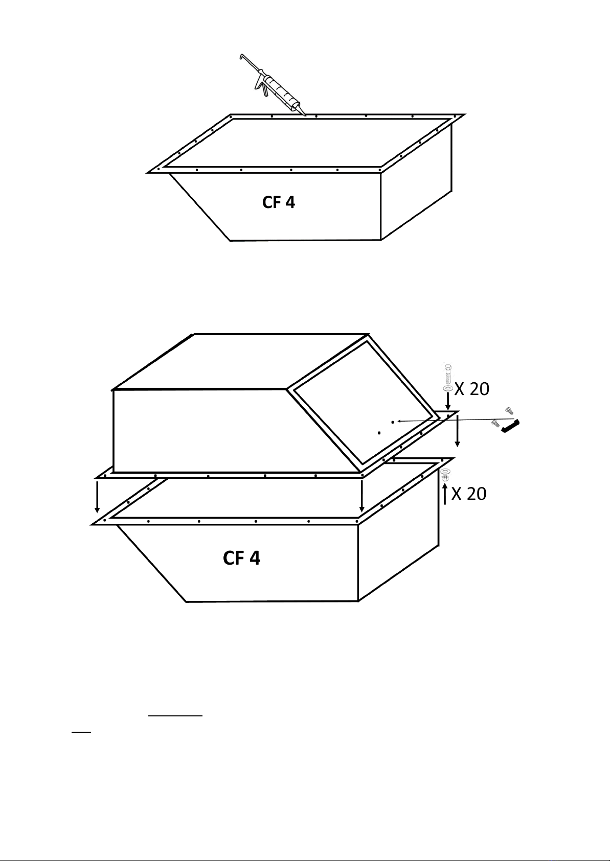
Assembly of the CF 4 System’s Composting Container
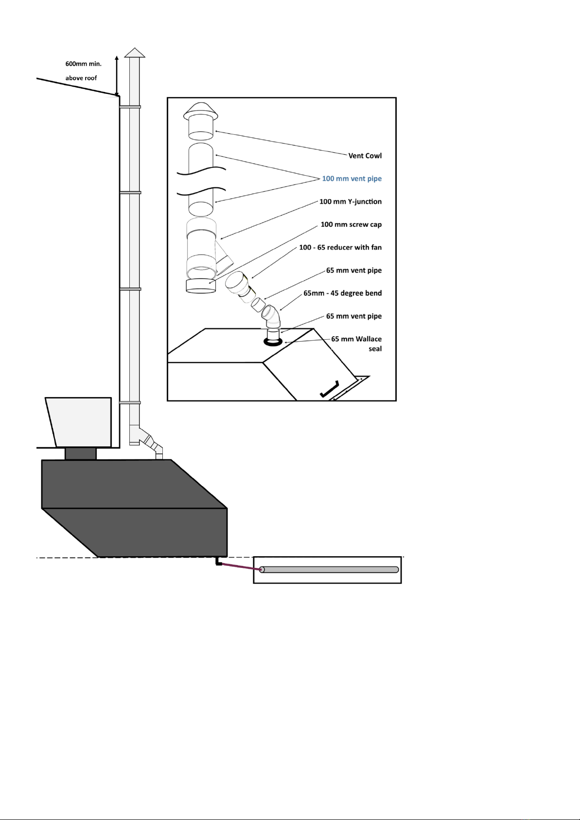
Space Required
There is no ideal set of measurements which will suit all applications, but you do need to provide enough
space to locate and install the composting container, enough space to fit and maintain the air vent piping
and fan and enough space to service the composting container via its hatch. The CF 4 is designed to achieve
this with a 325mm minimum space requirement if buried halfway up to the join line. However, the chute
allows for installations up to 1.1m high - and this can even be further extended with optional additional
chutes.
General considerations and tips
The composting container must be located directly below the toilet pedestal.
The composting power of the CF 4 System is increased if the unit can be installed pointing North -
exposed to sunlight. This warms the container and boosts the composting process.
Do not plan to install a light directly over the pedestal/waste chute as this will attract flying insects.
Always close the lid of the toilet after use
Do not use your bathroom fan! Its suction works against the suction of the fan of the CF 4.
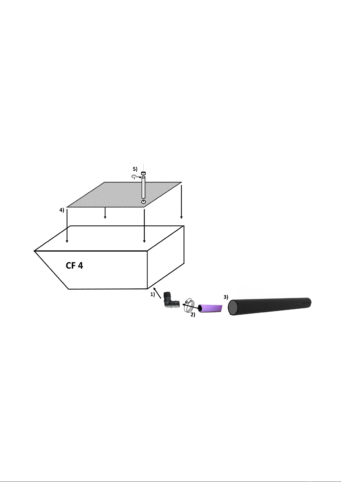
Installation - structural considerations
The CF System is installed sub-floor. It may be installed under a concrete slab or bearer and joist floor, in a
full or partial cellar as desired in the building design. Consider the spacing of joists or concrete slab
penetrations to allow for the waste chute. Ensure support member spacing and floor spans are adequate
for the position of the CF 4 and toilet pedestal. Install trimmer joists if necessary (this has to be carried out
by a licensed builder). Ensure no piping or wiring encroaches on the cut out.
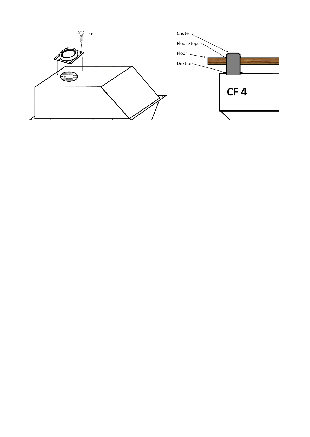
The first thing to do is to decide where in the toilet room you want to place the pedestal. Mark a centre
position for the waste chute using the pedestal as a guide. Drill a small hole through the centre point and
through the floor. Go to where the CF 4 is to be located below floor. Attach a plumb bob through the centre

4
point hole and consider the position and ensure there is enough room to fix the vent piping and fan and
there is adequate access to service the container via the hatch.
Check you have clearance in the joists for the waste chute to pass through the floor. Do not cut out the
waste chute hole in the floor until you are sure you have everything lined up in case you need to adjust the
position.
Prepare a flat, level ground for the CF 4 and dig out the excess liquids trench
The CF 4 can be installed at ground level or partially buried (up to the centre line). Dig out the excess liquids
trench as per below, allowing for the elbow and drain hose below the CF 4
Prepare the excess liquids trench, ready to receive the purple excess liquids drainage hose.

5
Assemble the CF 4 container and add bulking material
1) Thread the drain elbow into the liquids outlet on the bottom of the unit. Ensure you finish with the
elbow pointing in the direction of the excess liquids drain.
2) Secure liquids drain hose onto elbow firmly and fasten with hose clamp. Position the bottom half of
the CF 4 into its final position.
3) Do not yet connect up with slotted aggregate pipe of the excess liquids trench.
4) Insert the drainage tray - spacer pipes at the bottom, and drain outlet service hole at the front.
5) Slide drain service pipe into the hole in the front left of the bottom tray, secure in place with
supplied bracket & screws and cap off (see below).
Cover floor tray with 50mm of supplied bulking material. Wet down with a spray hose.
Run a 4 - 6mm silicone bead around the center of the flange of the bottom unit (silicone and caulking gun
supplied).

6
Put top unit on top of the bottom unit as per below. Line up the holes of the flanges and fasten with bolts,
washers and nuts (supplied).
Affix the handle with bolts (both supplied) through the pre-drilled holes
Cutting the hole for the waste chute and cutting the chute to length
Cut the waste chute hole in the toilet room floor to suit chute - approx. 250mm (+/- 2mm).
Insert the chute from above, tapered end up, through the hole you cut earlier. Firmly rest the chute onto
the CF 4. Measure the distance between the floor and the floor stops of the chute. Remove the chute and
cut this measurement less 50mm off the bottom of the chute so that when re-inserted later, it will protrude
50mm into the CF 4 container.

7
Cutting the waste hole in the CF 4 container and affixing the waste chute
Mark the centre of where the waste chute meets the CF 4. Remove the CF 4 and draw a 260mm circle and
cut out with a jigsaw or similar.
Cut the Dektite along the marked line to suit the 250mm chute and fit the Dektite centrally over the chute
hole, screwing it down with the self- tapping screws supplied.
Position the CF 4 back into its final position. Insert the waste chute through the floor into the Dektite on the
CF 4.

8
Connect the excess liquids outlet via the purple hose to the excess liquids trench.
Install the pedestal according to the instructions supplied with the pedestal.
Vent System - General Considerations
The vent outlet should be ideally placed at the front top of the unit (near the access hatch) but can
also be installed at the upper front of either side.
The CF 4 airflow requirement incorporates a continuous running fan (supplied). Consider how the
fan will be powered (240VAC or 12VDC). Ensure correct airflow of the fan away from the toilet.
Remember that warm air from the composting chamber (the composting process generates its own
warmth) naturally rises, and that sharp bends restrict airflow – designing the vent piping correctly
will improve operation. Avoid bends tighter than 45 degrees & in order to maximise air flow,
minimise the length of the piping between the composting container and the vent stack.
Warm air, holding moisture, entering a cold vent can result in condensation. Install the provided
Y-Junction and screw cap (your condensate trap) as per drawings.
Do not use pipe cement below the Y-junction – the push fittings should be tight enough for this
purpose. This allows you to exchange/service the fan and empty the condensate (moisture) trap as
required.
Vent Installation
The below is an example as to a standard vent installation – there are many permutations possible and if in
doubt, contact us for discussion and guidance. The 100mm vent pipe is not supplied for transport reasons
and is readily available from your local hardware or plumbing supplier.
Cut a 76mm diameter hole in the front top of the unit and insert the Wallace seal - you may find this easier
if you warm the seal in hot water first.

9
1. USE OF THE CF 4 SYSTEM
The CF 4 System can be used almost like any normal water toilet. Toilet paper can be thrown into the toilet,
as it composts together with the waste. However, any items containing plastic, e.g. including sanitary
products should be placed into a separate bin. A handful of covering material (hemp, 1 cup) should be
added after each bowel movement. The composting process can be enhanced even further by leveling and
mixing the compost occasionally. Our compost starter may also be added as per instructions to assist the
composting process.

10
2. SERVICE
a) Check the fan 1) monthly to ensure it is working or 2) if you notice unusual odour.
b) Check the condensate trap every 3 months by unscrewing the cap at the bottom of the Y-junction -
empty & replace. (A small tap may also be inserted into the screw cap instead of this process).
c) Rake the fresh contents from under the pedestal to the front of the unit
a. when the contents reach the top of the unit at chute point, or
b. after 3 months.
d) Repeat as necessary - this ensures that the oldest compost is at the front closest to the hatch.
Remember that the compost continually reduces in volume as it matures.
e) Remove the compost from the front of the unit as per steps 1, 2 & 3 below:
a. When the unit is full,
b. after 6 months or
c. when fully broken down.
f) Every 6 months check the excess liquids outlet via the service pipe. Remove the cap, inspect visually
and if blocked (or uric crystals are forming) insert garden hose right to the bottom and gently flush
out. Replace cap.
To service the CF 4 System, protective clothing, face mask, glasses and gloves must be worn at all times.
3. USE OF COMPOST
Bury the contents of the container into a prepared area. Burial depth is a minimum of 300mm in soil
that is not intended for human food cultivation for six (6) months, and
✔Burial should be a minimum of 30 metres from any water source and 6 metres from any sub-soil
or open drainage system, or
✔Dispose of as directed by the Local Government.

11
Dear Friend,
Thank you very much for choosing our CF 4 Bio Sanitation Systems.
We hope that you enjoy many years of fruitful, waterless, and
trouble-free use.
Please do not hesitate to contact us with any questions, suggestions,
we are here to help.
Feedback is always welcome and is an invaluable part of providing an
excellent product and service!
Finally, thank you for being an integral part of the environmental
solution. The Earth will thank you too!
“Save the World by Sitting Down!” ®
The Team at Green Loo
Green Loo NZ
23
Teviotview Pl
Amberley, 7410
info@greenloo.org.nz
@infogreenloo.org.nz
www.greenloo.org.nz
Table of contents
Other GREEN LOO Toilet manuals
Popular Toilet manuals by other brands

INCINOLET
INCINOLET WB Installation & maintenance manual

Kohler
Kohler K-3489 Series Installation and care guide

Raymor
Raymor Edge II 203147 installation instructions

Helvex
Helvex BOLMEN2 installation guide

Star
Star PowerFlush Optima S1201 manual

noken
noken Acro Compact 100268639-N380000066 installation instructions