MASTER ONE – TECHNICAL DOCUMENTATION Page 6
2.2 Electrical connection
The electrical installation of the MASTER ONE must be performed by a qualified electrician.
The MASTER ONE should be connected to the single-phase 230 VAC on the terminals N-L-PE. Maximum
power consumption of the MASTER ONE is 30 W.
Electric shock hazard! Please make sure that the main power supply is turned off before
trying to connect the power to the MASTER ONE. In any case, working under voltage shall
be avoided.
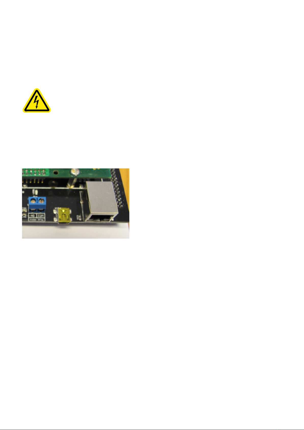
2.3 Connection to the LAN network
The network cable can be introduced above or below the MASTER ONE and it should be connected
onto the RJ45 socket, which is located under the screen. If the MASTER ONE is equipped with the
contactless payment module the RJ45 socket is located on the switch.
2.4 Internet connection
There are two possible means of internet connection, by UMTS 3G or by RJ45 cable.
For UTMS 3G/4G connection, the modem is installed by Green Motion when ordering the charging
station. 3G/4G network coverage must be checked before installation of the MASTER ONE is carried out.
Green Motion does not recommend using the 3G/4G network in an underground car parking or in areas
that have poor mobile network services.
Green Motion can also install a fiber optic SC port to ethernet RJ45 converter (multimode type or single
mode type). (Quote on demand).
The charging station and the payment system are configured in DHCP. It is not possible to assign fixed IP
addresses to the equipment. If it is essential to use a fixed IP address, Green Motion can install an
additional router in the charging station.