Myenergi ZAPPI-2H07UW-G User manual

Rev 1.2 November 2022 – ENGLISH
zappi
eco-smart EV charge point
User Manual
MODELS:
ZAPPI
-2H07UW-G
ZAPPI-2H07UB-G
ZAPPI-2H07TW-G
ZAPPI-2H07TB-G
ZAPPI
-2H22UW-G
ZAPPI-2H22TW-G
ZAPPI-2H22UB-G
ZAPPI-2H22TB-G

Page 2of 29
Contents
1. Introduction.................................................................................................................................................................................5
2. Safety............................................................................................................................................................................................5
3. Disposal ........................................................................................................................................................................................5
4. Copyright......................................................................................................................................................................................5
5. Overview.......................................................................................................................................................................................6
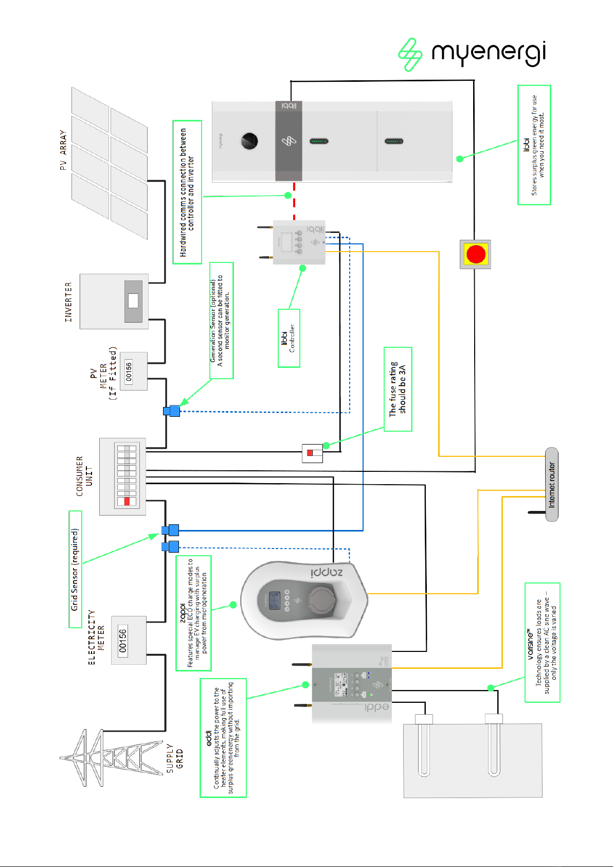
5.1 Overview Diagram............................................................................................................................................................6
6. Box Contents...............................................................................................................................................................................8
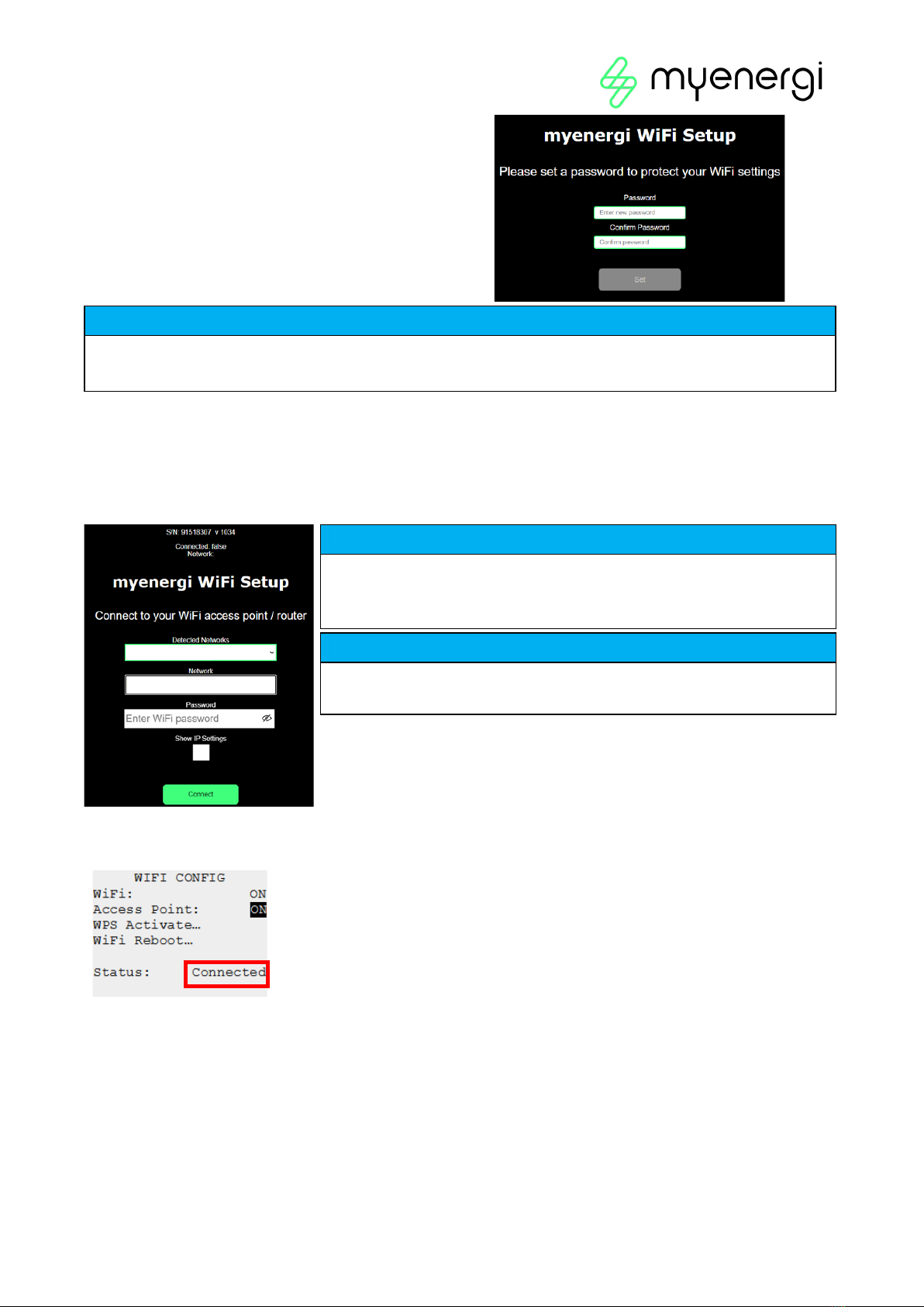
7. WiFi Set-up ..................................................................................................................................................................................8
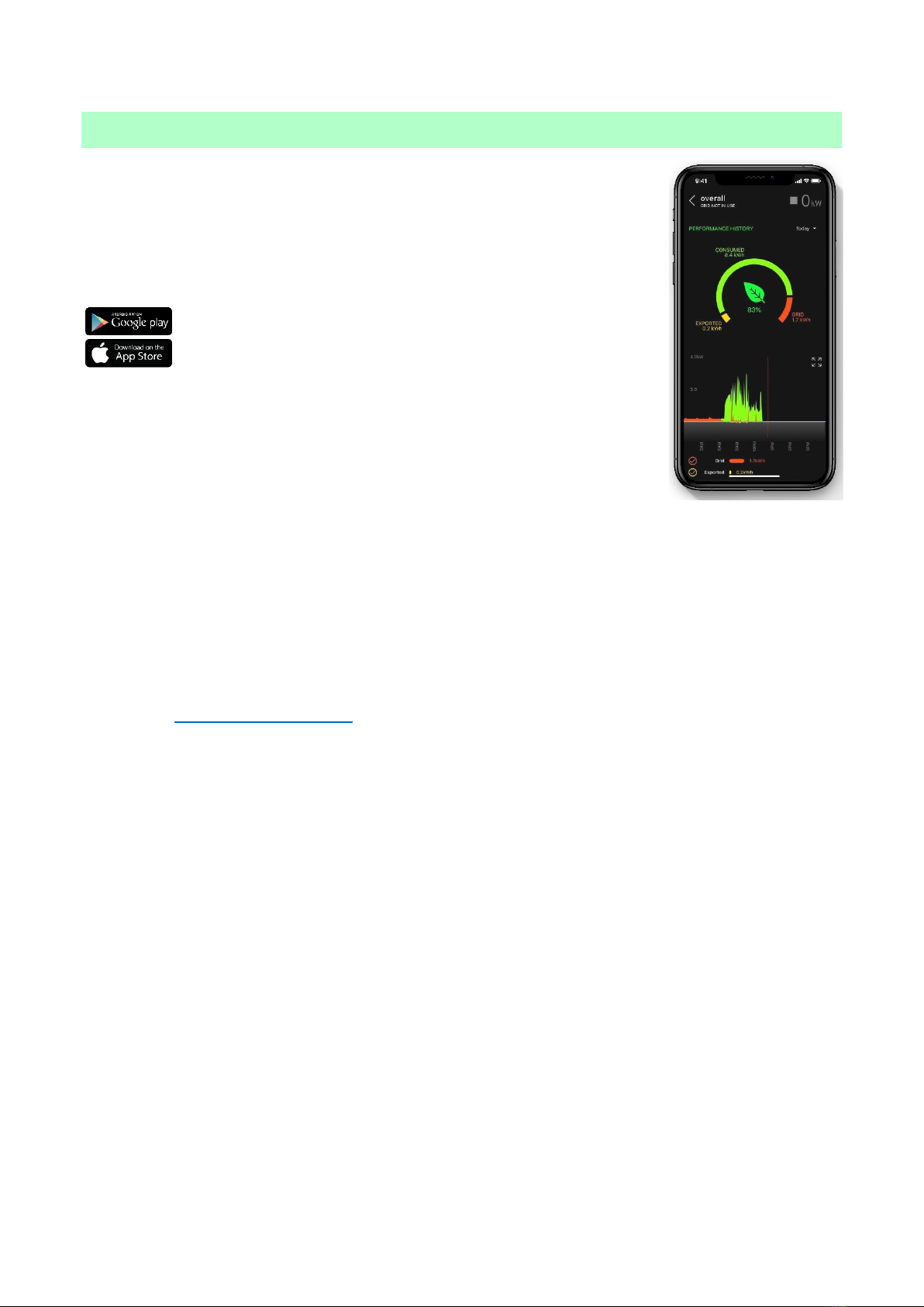
8. Product Registration..............................................................................................................................................................10
8.1 First Time User? Register for an Account............................................................................................................... 10
8.2 Existing Users ..................................................................................................................................................................10
9. Operation .................................................................................................................................................................................... 11
9.1 Controls & Indicators...................................................................................................................................................... 11
9.2 Display................................................................................................................................................................................ 12
9.3 Status Screens................................................................................................................................................................. 13
10. Charging Modes....................................................................................................................................................................... 15
11. Manual Boost ............................................................................................................................................................................ 16
12. Troubleshooting........................................................................................................................................................................17
13. Fault Codes................................................................................................................................................................................ 18
14. Warranty..................................................................................................................................................................................... 19
15. Technical Specifications.......................................................................................................................................................20
15.1 Performance....................................................................................................................................................................20
15.2 Electrical Specifications..............................................................................................................................................20
15.3 Mechanical Specifications...........................................................................................................................................20
15.4 Connectivity ....................................................................................................................................................................20
15.5 Max Transmitted Power...............................................................................................................................................20
16. Model Variants.......................................................................................................................................................................... 21
17. Technical Support ................................................................................................................................................................... 21
Appendix A........................................................................................................................................................................................ 22
1. Electric Vehicles (Smart Charge Points) Regulations 2021...................................................................................... 22
1.1 Purpose of the Regulations........................................................................................................................................ 22
1.2 What’s changed with zappi......................................................................................................................................... 22
1.3 Randomised Delay: How it works.............................................................................................................................. 22
1.4 Smart Scheduling: How it works ............................................................................................................................... 23
1.5 Defaulting to ‘ECO+’ Mode ......................................................................................................................................... 23
1.6 Charging Logs.................................................................................................................................................................24

Page 3of 29
Appendix B ........................................................................................................................................................................................25
2. Electric Vehicles (Smart Charge Points) Regulations 2021......................................................................................25
2.1 Purpose of the Regulations........................................................................................................................................25
2.2 What’s changed with zappi.........................................................................................................................................25
2.3 Automatic Firmware Checking.................................................................................................................................. 26
2.4 Tamper Detection.......................................................................................................................................................... 26
2.5 AES Encryption............................................................................................................................................................... 26
2.6 Installer Requirements..................................................................................................................................................27

Page 4of 29
NOTICE
The UK Government’s Electric Vehicle (Smart Charge Points) Regulations 2021 have been introduced.
Please ensure you read this manual fully before installing. Processes and features have changed.
Electric Vehicles (Smart Charge Points) Regulations 2021
From 30th June 2022, any EV charger installed in a private setting i.e. home or workplace,
NOT public, in England, Scotland and Wales has to meet the Electric Vehicles (Smart Charge
Points) Regulations 2021.
From 30th December 2022, further regulations come into force.
To ensure all our zappis are compliant by the date the regulations come into force we will
be taking a phased approach with the implementation of certain features.
For information on how these new regulations may affect you and your myenergi zappi
please read the appended information at the back of this manual.
Appendix A – (Electric Vehicle Smart Charge Points) Regulations 2021 – Regulations as of
30th June 2022
This Appendix is relevant to all zappis INSTALLED on or after the 30th June 2022
Appendix B- (Electric Vehicle Smart Charge Points) Regulations 2021 – Regulations as of
30th December 2022.
This appendix is relevant to zappis INSTALLED on or after 30th December 2022.

Page 5of 29
1. Introduction
Thank you for choosing zappi. Of course, we think you have made an excellent choice and are sure you will be
incredibly happy with the features, benefits, and quality of your myenergi product.
These instructions will help you to familiarise yourself with the zappi. By reading the instructions, you will be
sure to get the maximum benefit from your 'eco-smart' device.
2. Safety
zappi is an AC EV charger, intended to be installed in a fixed location and permanently connected to the AC
supply network. It is a Class 1 item of electrical equipment in accordance with IEC 61140.
The unit is designed for indoor or outdoor use at a location with restricted access and should be mounted
vertically either surface (wall) mounted or on the dedicated pole mount supplied separately by myenergi.
The device hasbeen manufactured in accordance with the stateof theart and the recognised safetystandards,
however, incorrect operation or misuse may result in:
•Injury or death to the operator or third parties
•Damage to the device and other property of the operator
•Inefficient operation of the device
All persons involved in commissioning, maintaining, and servicing the device must:
•Be suitably qualified
•Have knowledge of and experience in dealing with electrical installations
•Read and follow these operating instructions carefully
•Always disconnect the device from the supply before removing the cover
The device is not to be used by persons (including children) with reduced physical, sensory, or mental
capabilities, or lack of experience and knowledge, unless they have been given supervision or instruction
concerning use of the device by a person responsible for their safety.
zappi comes in either tethered or untethered variants. The untethered version should only be used with a
dedicated cable fitted with a Type 2 plug which is compliant with EN 62196-1 and EN 62196-2. Adaptors or
conversion adapters and cord extension sets are not allowed to be used.
Failure to install and operate the zappi in accordance with these instructions may damage the unit and
invalidate the manufacturer’s warranty.
3. Disposal
1
In accordance with European Directive 2002/96/EC on waste electrical and electronic equipment and its
implementation in national law, used electrical devices must be collected separately and recycled in an
environmentally responsible manner. Ensure that you return your used device to your dealer or obtain
information regarding a local, authorised collection and disposal system. Failure to comply with this EU
Directive may result in a negative impact on the environment.
4. Copyright
Copyright of these operating instructions remains with the manufacturer. Text and images correspond to the
technical level atthe time of going topress. We reservethe right tomakechanges.The content of the operating
instructions shall not give rise to any claims on the part of the purchaser. We are grateful for any suggestions
for improvement and notices of errors in the operating instructions.
myenergi zappi, myenergi eddi and myenergi harvi are registered trademarks of myenergi Ltd.

Page 6of 29
5. Overview
Microgeneration systems such as Solar PV and small wind turbines are at their most efficient when the
generated energy is consumed on-site rather than exporting it to the grid. This is what we call 'self-
consumption'.
zappi is a Mode 3 charging station, compatible with all electric vehicles that comply with EN 62196 and EN
61851-1 plug-in electric vehicle standards.
zappi works like any regular charging point but has special ECO charging modes that will benefit homeowners
with grid-tied microgeneration systems e.g. wind or solar generation. Two special ECO charging modes
automatically adjust charging current in response to on-site generation and household power consumption. In
FAST charge mode, zappi operates like an ordinary EV charger.
A grid current sensor (supplied) simply clips around the incoming supply cable and is used to monitor excess
power. When using the special ECO charge modes, zappi will automatically adjust the charge rate in response
to available surplus.
Feature Set
•3 charging modes: ECO, ECO+ & FAST
•Optimises microgeneration self-consumption
•Works with solar PV, wind turbine or micro-hydro systems
•Economy tariff sense input
•Programmable timer function
•Charge and event logging
•Remote control and monitoring add-on option
•Pin-code lock function
•Tap operated display backlight
•Built-in protection against the loss of the protective neutral and earth (PEN) conductor as required by BS
7671:2018 Amendment 1:2020(The “Wiring Regulations”)
•Ethernet connector (for local communications between myenergi devices)
•Integral cable holster (tethered units)
•Supplied with 1 x clip-on grid current sensor (x3 if purchasing a 3-phase unit)
•Illuminated display – for convenience, the display can be illuminated by simply tapping the zappi front
cover.
•Integrated WiFi for connecting to internet.
•Front Lid Tamper Detection
5.1 Overview Diagram
The diagram on the next page shows the zappi as part of a complete energy management system. Other
myenergi products are shown with details of how they integrate with the grid connection and the
microgeneration system.

Page 7of 29

Page 8of 29
NOTICE
Make a note of the SSID and Password (P/W) now, for use in the next steps.
6. Box Contents
Tethered Units
Untethered Units
•1 x zappi unit with EV cable and connector attached
•1 x Cable wall guard
•1 or 3 x CT clamps1
•1 x Mounting template
•1 x Mounting kit for a brick wall
•1 x zappi unit
•1 or 3 x CT clamps1
•1 x Mounting template
•1 x Mounting kit for a brick wall
Mounting kit (Tethered units)
Mounting kit (Untethered units)
•4 x 50mm Pozi screws
•4 x Wall mounting plug
•4 x Sealing washer
•4 x 12mm Pozi screws (countersunk)
•4 x 50mm Pozi screws
•4 x Wall mounting plug
•4 x Sealing washer
7. WiFi Set-up
If WiFi was not available during your installation, your installer may have skipped this step. As soon as you
have WiFi availability you can connect by following the steps below.
It is important to connect your zappi to the internet to install the latest firmware and receive any future
firmware updates.
Step 1:
Firstly, turn on the Access Point by navigating to Menu > Other Settings > Internet > WiFi > WiFi
Information on your zappi device display. If Access Point is showing as “Off”, turn to “On”.
Step 2:
Once the Access Point is set to “On”, go back to the “WiFi” page by pressing the (
≡
) button.
Step 3:
Connect your smartphone or computer to the myenergi access point by entering your phone or
computer WiFi Settings and searching for the network displayed with the same name as the SSID you noted
down above. Once displayed, select the network to connect.
Step 4:
You will be prompted for a
password.
Enter the password displayed on the
zappi screen that you noted down at
step 2.
11xCT clamp supplied with single phase zappi; 3xCT clamps supplied with three phase zappi

Page 9of 29
Step 5:
You will now be prompted to create a
new password to protect the WiFi settings from
being changed by anyone else. The newpassword
must be at least 8 characters long and consist of
a combination of lowercase and uppercase letters
and digits.
Step 6:
Wait 5 seconds for your password to change and the webpage to reload.
Step 7:
Once connected, you will be directed to the webpage below where you will need to select your
home WiFi network from the list in the “Detected Networks” box and type in your home WiFi’s password to
connect to your router.
Step 8:
Once complete, check WiFi is connected. Do this by navigating back to the WiFi Config Menu as
you did at Step 1. Check Status is showing as “Connected”.
NOTICE
If page doesn’t load, type 192.168.4.1 into your web browser of mobile phone browser to enter WiFi setup
screen.
NOTICE
In most cases you should leave the “Show IP Settings” option unticked.
However, if you want to give your zappi a fixed IP address then tick the
“Show IP Settings” box and fill in the extra information required.
NOTICE
Please be patient. It could take up to 15 seconds for the connection to
take place.

Page 10 of 29
8. Product Registration
8.1 First Time User? Register for an Account
If this is your first myenergi device your installer will talk you through the
following simple steps to get your account up and running.
Step 1: Download the myenergi app
Android users can download the myenergi app on Google Play
Apple users can download the myenergi app in the App Store
1. Open the app and click, ‘Register for an account’.
2. Enter an email address and create a password, when prompted.
3. Select your contact preferences then click ‘next’.
4. Check the email you registered with for a verification code.
5. Enter the code into the app, where requested and press ‘next’
Step 2: Set your location and add your first device
1. In the app click the green ‘+’ symbol to add your first location.
2. When asked if you have a ‘hub’ select,‘No’ as this is your firstdevice which already has a built-in virtual
hub (vHub).
3. Enter the ‘Reg S/N’ and ‘Reg code’ (These can be found in your zappi device settings; menu >
Information > Page 2.).
4. Once complete, your device will now display in your myenergi account and app.
Step 3: Customer Details
1. Visit myaccount.myenergi.com from a web browser.
2. Log in with the same credentials used to register for the app.
3. Click on ‘My Dashboard’.
4. In the section titled ‘Finish setting up your account’, click ‘Add account details’.
5. Click ‘Edit personal info’ and complete the form with the required information.
6. Click, ‘Submit’.
Congratulations! You’re all set. You can now use the myenergi app and myaccount to monitor your energy
consumption in real time, wherever you are in the world.
8.2 Existing Users
Already have a myenergi device and registered account?
1. Your installer will pair your new device to your existing system.
2. You will see your new device is automatically added to your myenergi account and app.

Page 11 of 29
9. Operation
9.1 Controls & Indicators
1. Display Graphical LCD display with LED backlight
•Backlight can be activated by tapping the unit.
2. Front Fascia Remove fascia for installing and servicing
3. Tethered Charging
Cable if applicable
6.5-metre cable with a Type 2 plug or Type 2 socket with locking
system for untethered models.
4. Control Buttons Four tactile buttons used to navigate the menus and alter
settings:
Menu
Change charge mode | Move up a menu item | Increase
value
Change charge mode | Move down a menu item | Decrease
value
Boost | Select item | Confirm value and move to next
setting.
5. Integrated Cable
Holster (tethered units
only)
When not in use, the charging cable should be wrapped around
the unit and secured in the cable holster (tethered units).
6. Charging Connection
Point (untethered units)
When cable not in use, the charging cable should be unplugged
and stored in a cool dry place.
7. RGB Indicator Visual Indicator that changes colour dependant on the zappi's
charging state.

Page 12 of 29
9.2 Display
1. Import / Export
Power The power being either imported or exported from or to the grid (kW).
The direction of the arrows indicates if the property is currently
importing power (left) or exporting power (right).
The size of the arrows is proportionate to the level of power being
imported / exported, When the property is neither importing or
exporting power the figure will be 0.0kW and there will no animated
arrows. The property is then said to be 'in balance'.
2. House Load
Power The power that the property is currently using in kW. (Note: This is
displayed only when the Generation Sensor is installed directly to a CT
input or a
harvi
or other
myenergi
device)
3.
Status Text
The current status is displayed here (see Status Screens)
4. Generation
Power The power being generated at this time in kW. (Note: This is displayed
only when the CTs are installed either hard wired to the CT inputs of the
zappi
or wirelessly to a
harvi
or other
myenergi
device)
5.
Lock Icon
Operation lock is active.
6.
Date & Time
The current date and time.
7. Mode Icons These icons indicate that the import limiting is active (house), Demand
Side Response (~) or the eSense input is live (e)
8. zappi Icon If you see wavy lines above the zappi icon, the unit is thermally limiting!
The output power is temporarily reduced.
9. Charge Mode Shows the selected Charging Mode; FAST, ECO or ECO+ (see Charging
Modes)
10. Charge
Delivered to EV
The accumulated charge energy that has been sent to EV in this charge
session.
11. Current
Charging Power
When the EV is charging, arrows will show here along with the charging
power in kW.
12. Green Level of
Last Charge
This is the percentage of 'Green' energy for the last charge session, this
is shown at the end of a charge or when the EV is unplugged.

Page 13 of 29
9.3 Status Screens
9.3.1 EV Disconnected
The EV is not connected to
zappi
.
In this example the last charging session delivered 20.8kWh of
energy to the EV and 80% of that energy came from the solar
panels.
9.3.2 Waiting for Surplus
zappi
is waiting for sufficient surplus power from the
microgeneration system. This screen will be shown in ECO+
mode as it is only in this mode that charging will stop if there is
not enough surplus power.
The house in the centre is straight-faced as grid electricity is
being used by the house (0.9kW in the example shown).
9.3.3 Surplus
Enough surplus is available and
zappi
is about to charge the EV.
A timer is decremented and can be set in the charge settings
(ECO+ mode only).
9.3.4 Waiting for EV
zappi
is waiting for the EV to respond; the EV is not ready to
accept charge.
9.3.5 Charge Delayed
The charging session has been delayed by the EV because a
scheduled charge has been set in the vehicle.

Page 14 of 29
9.3.6 Paused
zappi
is paused for a few seconds in order to limit the start/stop
frequency during ECO+ mode charging.
9.3.7 Charging
The EV is charging.
In this example the car is charging in ECO+ mode at 1.6kW, there
is no import or export from the grid (0.0kW) and the EV battery
has charged by 8.9kWh since the car started.
9.3.8 Charge Complete
The EV is fully charged.
The chargeenergy usedduring thelast charge is displayed at the
bottom right (20.0kWh in this case) and the 'green contribution'
is also shown (40% in this example).
9.3.9 Restart
zappi
is performing a restart sequence.
This may happen with some EVs that need to be 'woken-up' to
start charging after a pause in the charge. Charge should start
immediately afterwards, otherwise the “Charge Delayed”
message will appear.
9.3.10 Stopping
zappi
is about to stop the EV charging

Page 15 of 29
10. Charging Modes
zappi has three different charging modes and a “STOP” mode which can be selected simply by pressing the
and buttons when the main screen is showing. The charge mode can be changed before or during a
charge. Regardless of the charge mode, all the surplus electricity is used. zappi’s special eco charge modes
limit the amount of grid electric used. Below is the explanation of each charging mode.
Charges at the fastest rate
Fast Mode will charge the EV at the fastest rate and will import grid electricity if there is insufficient surplus
generated power. The actual charge rate is dependent on the EV's onboard charger and the grid supply
voltage. Some vehicles can charge at 11kW or 22kW on a 3-Phase zappi, but many EV's have lower charge
rates. The maximum charge rate for the single phase zappi is 7kW.
Adjusts the charge rate to limit the use of grid electricity
The charge rate is continuously adjusted, in response to changes in generation or power consumption
elsewhere in the home, thereby minimising the use of grid power. Charging will continue until the vehicle is
fully charged, using available surplus power. If at any time, the available surplus power falls below 1.4kW,
the shortfall will be drawn from the grid.
Note: The EV charging standard does not support below 1.4kW.
Adjusts the charge rate to limit the use of grid electricity and will pause the charge
if there is too much or any grid electricity being used (Set-up Dependant)
The charge rate is continuously adjusted, in response to changes in generation or power consumption
elsewhere in the home, thereby minimising the use of grid power. Charging will pause if there is too much
imported power, continuing only when there is enough surplus power available. The surplus powerthreshold
at which the charge will start or stop can be set using Min Green Level in the ECO+ Settings of the Charge
Settings menu. The actual green contribution percentage is shown when the charge is complete or when
the zappi has been disconnected from the EV. It is possible to charge the EV using only surplus renewable
power, if there is sufficient surplus power available and a boost option has not been set. (Please note: The EV
charging standard does not support charging below 1.4kW) Example: when zappi is set to a Min Green Level
of 100%you will need in excessof around1.4kW ofsurplus energy available to start the charge.If the surplus
falls below the 1.4kW threshold the charge will pause until the threshold is once again met. After a short
delay zappi will resume charge. If preferable, you can set the zappi to share power from the grid and a
generation source to ensure a charge is always maintained. For example, the Min Green Level could be set
to 75%. A charge will then start when there is a surplus of 1.05kW, taking a further 0.35kW from the grid. It
is worth noting that this is only required to start a charge. If a higher amount of surplus becomes available it
will be consumed, resulting in less being drawn from the grid.
The output from
zappi
is turned off
In STOP mode
zappi
will not charge your EV. This includes the boost modes and timed boost.
zappi
will
continue to measure power and communicate with the other myenergi devices.
FAST
ECO
ECO+
STOP

Page 16 of 29
11.Manual Boost
The Manual Boost function can only be used when charging in ECO or ECO+ mode. When boosting, the charge
rate is set to maximum (just like FAST mode), until a set amount of energy has been stored in the EV's battery.
After which, zappi will revert to ECO or ECO+ mode.
This function is useful if you arrive home with an almost flat battery and would like to charge the vehicle
immediately to ensure there is enough charge for a short trip if needed.
The amount of energy delivered to the EV during the boost charge can be changed in the Charge
Settings/Boost menu.
When in ECO or ECO+ mode, each press of the button will cycle through the boost options as illustrated below:

Page 17 of 29
12. Troubleshooting
Symptom
Cause
Solution
Display is blank
•
There is no power to the
unit
•
Check for correct supply voltage at the
supply screw terminals (220 - 260V
AC)
In ECO+ mode, the
charge does not
start, the display is
always showing
Waiting for Surplus
and the export
power is 0W
•Grid Sensor incorrectly
installed
•Faulty Grid Sensor
•No signal from harvi (if
used)
•Check the grid sensor is connected to a
CT terminal in the zappi
or any CT
input in the harvi
•Check the Grid CT sensor is installed on
the correct cable (see
CT Sensor
Installation)
•Check resistance of the sensor - it
should be around 200Ώ
when not
connected (remove the sensor from
the cable before testing resistance)
•If using harvi, check that the CT input
has been set to Grid in the harvi
settings (under
Linked Devices /
Devices in the zappi Advanced
Settings menu)
In ECO+ mode, the
charge does not
start, the display is
always showing
Waiting for Surplus,
yet the export power
is showing correctly
•Export Margin set too
high
•Check Export Margin setting (default is
0W)
Generation power is
always 0kW
•Generation CT not
installed
•Install generation sensor and connect
to one of the CT inputs
•Alternatively, if there is no Generation
CT, the Generation and House
consumption figures can be hidden on
the main screen by changing the Icons
setting in the
Settings / Display &
Sound menu
Installation Limit !
displayed
Display will show the
phase(s) that is(are)
overloaded and the
prospective current
that would be drawn
if the zappi were
allowed to start
charge at the
minimum current
•The measured Grid
Current is greater than
the Grid Limit set in the
zappi
•Check the Grid Limit setting
•Reduce the load in the property
•In a three phase installation, consider
rebalancing the property load across
the three phases

Page 18 of 29
Installation Limit !
CT displayed
•
The Grid CT has become
disconnected or is not
clamped correctly
around the grid supply
cable
•
Check CT is installed correctly.
13. Fault Codes
If any of the following fault messages are displayed, follow the action described.
Displayed Message
Description
Action
Unknown Cable !
zappi
has detected an unknown
EV cable (untethered units only)
Make sure you are using genuine
IEC 62196-2 compliant plugs.
Range supported: 32A, 20A and
13A.
zappi
will automatically retest the
cable after 5 seconds.
If the issue persists, unplug the
cable check for dirt in the plug and
try again.
Pilot problem !
zappi
has detected an issue with
the “Control Pilot” signal on the
cable between the zappi and the
EV.
zappi
will automatically retest the
cable after 5 seconds.
If the issue persists unplug the
cable, check for dirt in the plug
and try again.
Lock Failure !
Fault code 23
The socket lock actuator couldn’t
lock/unlock the inserted plug as
expected (untethered units only).
This message can happen when
the plug is not fully inserted or if it
is twisted or pulled from the
socket.
Push the plug fully into the zappi
to release the plug, then press and
hold the
button to reset the
unit.
Output Fault !
Fault code 24
zappi
has detected a wrong
output voltage. e.g. a voltage has
been detected when it should be
off.
Unplug the EV, press and hold the
button to reset the unit.
PE Fault !
Fault code 25
zappi
has detected a problem
with the main earth connection to
the unit. The earth is either
disconnected or the impedance of
the earth connection is too high.
Unplug the EV, check the earth
connection to the zappi and then
hold the
button to reset the
unit.
If the electricity supply is “IT
earthed” check the Supply Grid /
Earthing menu setting.
Comms Fault !
Fault code 26
zappi
has detected an issue with
the built-
in protection
components.
Unplug the EV, press and hold the
button to reset the unit.
SelfTest Failed !
Fault code 27
The built-in protection devices
couldn’t be tested or failed the
test prior to a charge.
Unplug the EV, press and hold the
button to reset the unit.
Contactor Fault !
Fault code 28
The relay inside the zappi has a
welded contact. The secondary
Unplug the EV, press and hold the
button to reset the unit.

Page 19 of 29
relay is open to make sure that the
supply to the EV is isolated.
PEN Fault!
Fault code 29
The internal protection against
the loss of the PEN conductor on
the electricity supply has tripped.
Unplug the EV, make sure that the
fault hasbeenremoved thenpress
and hold the button to reset the
unit.
Overload !
Fault code 30
The EV is drawing too much
current –
the output is switched
off.
Unplug the EV, press and hold the
button to reset the unit.
Bad Voltage Range !
Over Voltage!
Under Voltage!
Fault code 31
zappi
has detected that the
supply voltage is too high/low and
has disconnected the EV to
protect it.
Unplug the EV, make sure that the
fault has been removed and hold
the button to reset the unit.
Overheating!
The
zappi
unit is too hot – the
output is switched off.
Make sure that the
zappi
is
properly ventilated (e.g. has not
been covered).
Charge will resume once the unit
has cooled down again.
Voltage Mismatch !
Fault code 32
The output voltage detected by
zappi and the built-in protection
components is not the same.
Unplug the EV, press and hold the
button to reset the unit
Charge Blocked !
zappi
has detected that the EV
has repeatedly tried to start a
charge even though th
e EV has
previously reached “Charge
Complete” i.e. The battery is full,
the battery has reached a charge
level set in the EV, or the charge
has been stopped by a timer in the
EV.
Unplug the EV
Charging will continue when the
EV is plugged in again
If any of the above faults persist then stop using zappi and contact your supplier or myenergi Technical
Support.
14. Warranty
Full details of the myenergi product warranty are available on our web site or by using this QR code.

Page 20 of 29
15. Technical Specifications
15.1 Performance
Mounting Location
Indoor or Outdoor (permanent mounting)
Charging Mode
Mode 3 (IEC 61851-1 compliant communication protocol)
Display
Graphical backlit LCD
Front LED
Multicolour, according to charge status, current and user setting
Charging Current
6A to 32A (variable)
Dynamic Load Balancing
Optional setting to limit current drawn from the unit supply or the grid
Charging Profile
3 charging modes: ECO, ECO+ or FAST. STOP is a further option
Connector Type
Type 2 tethered cable (6.5m) or type 2 socket with locking system
Compliance
LVD 2014/35/EU, EMC 2014/30/EU, EN 62196-2:2017, ROHS
2011/65/EU, CE Certified, EN 61851-1:2019*
*
zappi
complies fully with EN 61851-1:2019 with the exception of Clause 8.4 in order to meet the requirements of BS
7671:2018 Amendment 1:2020 which requires the protective earth conductor to be switched in order to provide protection
against a damaged PEN conductor in a TN-C-S earthed electrical system.
15.2 Electrical Specifications
Rated Power
7kW (1-phase) or 22kW (3-phase)
Rated Supply Voltage
230V AC Single Phase or 400V AC 3-Phase (+/- 10%)
Supply Frequency
50Hz
Rated Current
32A max
Standby Power
Consumption
3W
Economy Tariff Sense
Input
230V AC sensing (4.0kV isolated)
Wireless Interface
868 MHz / 915 MHz (-A units) proprietary protocol for wireless sensor
and remote monitoring options
Grid Current Sensor
100A max. primary current, 16mm max. cable diameter
Supply Cable Entry
Rear / Bottom / Left side / Right side
15.3 Mechanical Specifications
Enclosure Dimensions
439 x 282 x 122mm
Protection Degree
IP65 (weatherproof)
Enclosure Material
ASA 6 & 3mm (UL 94 flame retardant) colours: white RAL 9016 and grey
RAL 9006
Operating Temperature
-25°C to +40°C
Fixing Points
In-line vertical mounting holes
Weight
Single Phase Untethered: 3.0kg
Single Phase Tethered: 5.5kg
Three Phase Untethered: 3.3kg
Three Phase Tethered: 7.2kg
15.4 Connectivity
WiFi 2.4 GHz 802.11BGN Connection up to 150 Mbps
WiFi Frequency Range 2412-2484 MHz
Radio Frequency Range 868-870MHz
Radio Frequency (Australia) 915MHz
15.5 Max Transmitted Power
Radio
25mW
WiFi
100mW
This manual suits for next models
7
Table of contents
Other Myenergi Automobile Batteries Charger manuals
Popular Automobile Batteries Charger manuals by other brands

NORAUTO
NORAUTO PREMIUM HF1500 instruction manual

Power Electronics
Power Electronics Ford Pro Standalone NB 240 manual

Fubag
Fubag Combi Starter Operator's manual

MasterForce
MasterForce 260-9514 Operator's manual

I.SOUND
I.SOUND 5913 user guide

ULTIMATE SPEED
ULTIMATE SPEED ULG 3.8 A1 BATTERY CHARGER Operation and safety notes