IBS ECL202 User manual

www.ibspe.com
User Manual | P1
ECL202/ECL202e

Last update: 2022-06-13
www.ibspe.com
User Manual | P2
Table of Contents
1APPROVALS AND SAFETY CONSIDERATIONS 3
2HELPFUL TECHNICAL SUPPORT DOCUMENTS ONLINE 3
3ECL202 AND ECL202E 4
3.1 DESCRIPTION 4
4QUICK START INSTRUCTIONS 4
5FRONT PANEL CONTROLS AND INDICATORS 5
5.1 LED RANGE INDICATOR 5
5.2 RESETTING OFFSET 5
5.3 SETPOINT BUTTON 5
6ANALOGUE OUTPUT SIGNAL 6
6.1 INTERPRETING THE OUTPUT VOLTAGE 6
6.2 CHANGE IN GAP CALCULATION: 6
7REMOTE OFFSET AND SETPOINT 6
8SETPOINT SWITCH OUTPUT 6
9BANDWIDTH SELECTION (ECL202 ONLY) 6
10 MAXIMISING PERFORMANCE 7
10.1 EXTENSION CABLES 7
10.2 PROBE MOUNTING 7
10.3 UNGROUNDED TARGETS 7
10.4 MULTIPLE SENSORS 7
11 CONNECTING TO THE ECL202 8
12 SPECIFICATIONS 9
13 MECHANICAL DETAIL 11

Last update: 2022-06-13
IBS Precision Engineering • Eindhoven • NL • +31 40 290 1270
User Manual | P3
1Approvals and safety considerations
The ECL202/ECL202e is compliant with the following CE directives:
Safety: 61010-1:2001
EMC: 61326-1, 61326-2-3
To maintain compliance with these standards, the following operating conditions must be maintained:
•All I/O connecting cables must be less than three meters in length
•AC power cables must be rated at a minimum of 250 V and 5 A
•AC power must be connected to a grounded mains outlet rated less than 20 A
•Power supply must have CE certification and provide safety isolation from the mains according to IEC60950
or 61010.
•Sensors must not be attached to parts operating at hazardous voltages in excess of 30 VRMS or 60 VDC
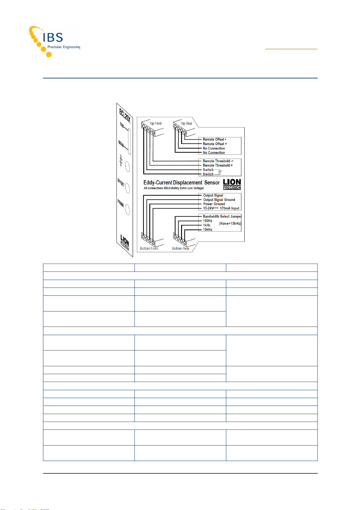
•All external connections must be SELV (Safety Extra Low Voltage).
Use of the equipment in any other manner may impair the safety and EMI protections of the equipment.
2Helpful Technical Support Documents Online
The IBS Precision Engineering’s website has a large selection of technical documents (TechNotes and Application
Notes) in the Technical Library. These documents provide detailed descriptions of the operation and use of the
products of IBS Precision Engineering.
The Technical Library can be accessed at:
https://www.ibspe.com/expertise/technical-resources
Some of the titles include:
•Understanding Capacitive and Inductive Sensors
•Comparing Capacitive and Inductive Sensors
•Z-height Measurement with Non-contact Sensors
•Sensor Operation and Optimization
•Using Capacitive Sensors in Vacuum Applications
•Understanding Electrical Runout When Using an Eddy-Current Sensor for Roundness Measurements
•Inductive Probe Cabling Considerations

Last update: 2022-06-13
www.ibspe.com
User Manual | P4
3ECL202 and ECL202e
The ECL202e is identical to the ECL202 except that the ECL202e resolution is never better than 0.2 μm. For this
reason, the ECL202e does not require an export license.
This manual will only refer to the ECL202, but all instructions apply to the ECL202e except where noted.
3.1 Description
The Lion Precision ECL202 Eddy-Current Displacement Sensor provides high resolution, noncontact
measurement of position changes of a conductive target. The system consists of driver electronics and a probe
calibrated for a specific material and range. The calibration information is detailed on a calibration certificate
which is shipped with the system.
The ECL202 provides a linear analog voltage proportional to changes in the target position and a digital switched
(setpoint) output with a user programmed switching setpoint.
4Quick start instructions
1. Connect the probe to the ECL202
Note: The ECL202 is calibrated to a specific probe identified by serial number. The probe serial number must match
the “USE PROBE S/N” label on the front of the ECL202.
2. Connect the output to a monitoring device.
3. Connect then apply power.
4. Adjust the probe position so the Range Indicator shows green.

Last update: 2022-06-13
IBS Precision Engineering • Eindhoven • NL • +31 40 290 1270
User Manual | P5
5Front panel controls and indicators
5.1 LED Range Indicator
The Range Indicator monitors and displays the probe position within its calibrated range. The graphic below
shows the indicator condition at various points within the calibrated range.
The LED Range Indicator is independent of the output voltage and not affected by the Offset button. Shifting the
output voltage by using the Offset button may allow an apparently valid output voltage to exist while the probe is
out of range. When the Near or Far LED is red, the probe is out of range and the output voltage is not a reliable
indication of the target position.
This function establishes a repeatable master point for reference measurements.
1. Place good part in the measurement area
2. Position probe to center 20% of range (center indicator LED)
3. Press Offset button
4. All subsequent measurements indicate deviation from center of range (5 V)
5.2 Resetting Offset
Hold the Offset button for four seconds to remove any output DC shift.
5.3 Setpoint Button
The ECL202 provides an adjustable setpoint at which a switched output activates. The output switch closes when
the output voltage is more positive (larger gap) than the user-adjusted setpoint. Pressing the Setpoint button will
set the threshold voltage to the current output voltage. The setpoint includes a 0.085V hysteresis, requiring that
the sensor output drop 0.085V below the setpoint voltage before the switched output opens.

Last update: 2022-06-13
www.ibspe.com
User Manual | P6
6Analogue output signal
The output signal is an analog voltage of 0-10 VDC. The output voltage is proportional to the probe-target gap. As
the probe-target gap increases, the voltage becomes more positive. See the included calibration certificate for
specific information.
6.1 Interpreting the Output Voltage
Output voltage change for a given change in the probe-target gap is called sensitivity. The sensitivity is listed on
the calibration certificate.
6.2 Change in gap calculation:
Gap Change = Voltage Change / Sensitivity
For example: With a sensitivity of 1V/2 μm and a voltage change of +3 V, the probe-target gap has increased by
6 μm.
7Remote offset and setpoint
The front panel Offset and Setpoint buttons can be activated remotely. Each remote input connects to an opto-
isolator. The functions are activated by applying 15-24 V to the remote control input terminals.
Note: Because the remote operation mimics front panel operation, activating the Offset function for more than four
seconds will restore factory default value for Offset.
8Setpoint switch output
When the output voltage is more positive than the user adjusted setpoint voltage, the output switch contacts will
close. These contacts have a maximum resistance of 2.5 Ω and can conduct up to 250 mA. The maximum
voltage that can be switched is 30VAC/60VDC. The output is a solid state switch closure and can conduct AC or
DC.
9Bandwidth selection (ECL202 only)
A jumper wire on the bandwidth connector selects sensor bandwidth. To select a bandwidth, connect the desired
bandwidth terminal to the Bandwidth Select contact. With no jumper, the bandwidth is 15 kHz. Bandwidth
specifications are -10%/+30%.

Last update: 2022-06-13
IBS Precision Engineering • Eindhoven • NL • +31 40 290 1270
User Manual | P7
10 Maximising performance
10.1 Extension Cables
Sensors which are calibrated with a probe extension cable must be operated with the extension cable to meet
specifications. Operating without the extension cable will result in inaccurate measurements.
10.2 Probe Mounting
If multiple probes are mounted together, they must be separated by at least three probe diameters.
The area within 3 probe diameters to the sides and 1.5 diameters behind should be kept clear of any metallic
objects other than the object to be measured. Otherwise, custom calibration will be required.
10.3 Ungrounded Targets
Ungrounded targets have the potential to inject noise into the sensor. If the output is unusually noisy, be sure the
target is grounded. On moving/rotating targets this can be accomplished with a small metal brush or thin piece of
metal which is connected to ground.
10.4 Multiple Sensors
When multiple sensors are used with the same target, the sensors must be synchronized. An interconnecting
circuit board connects to the rear of multiple drivers to provide synchronization signals. Multiple sensor orders are
shipped with the interconnect board in place and the drivers are pinned together as one unit.
CAUTION: It is critical that each ECL202 be connected to the probe indicated on the “USE PROBE S/N”
label on the front of each ECL202.

Last update: 2022-06-13
www.ibspe.com
User Manual | P8
11 Connecting to the ECL202
Connection
Description
Notes
Top-Rear Connector: Remove Offset
No Connection
No Connection
Remote Offset +
+ Opto-isolator input for
Remote Offset function
15-24 VDC Activates the function
Remote Offset −
−Opto-isolator input for
Remote Offset function
Top-Front Connector: Remote Setpoint and Switch Output
Remote Threshold −
−Opto-isolator input for
Setpoint function
15-24 VDC Activates the function
Remote Threshold +
+ Opto-isolator input for
Setpoint function
Switch
Contact 1 of switched output
Open: 30 VAC/60 VDC max
Closed: 250 mA max
Switch
Contact 2 of switched output
Bottom-Front Connector: Power and Analog Output
Power In
Input Power
Internally connected together
Power Ground
Power Ground
Output Signal Ground
Reference for output signal voltage
Output Signal
Output signal voltage
0-10 VDC
Bottom-Rear Connector: Bandwidth (ECL202 Only)
Bandwidth Selected
Common point for bandwidth
selection jumper
100Hz, 1kHz, 10kHz
Bandwidth selection, connected to
Bandwidth Selected
None = 15 kHz

Last update: 2022-06-13
IBS Precision Engineering • Eindhoven • NL • +31 40 290 1270
User Manual | P9
12 Specifications
Parameter
Specification
Notes
Power Requirement
15-24 VDC, 2.5W
Resolution @
15kHz
(Typical)¹,²
Nonferrous
0.006 to 0.008%F.S. (ECL202)
0.3 μm or higher (ECL202e)
Ferrous
0.007 to 0.1%F.S. (ECL202)
0.3 μm or higher (ECL202e)
See calibration sheet for specifics
Linearity¹
±0.2%F.S.
Error Band¹
±0.4%F.S.
Analog Output¹
0-10 VDC, 0 Ω, 15 mA max
Analog Output Update Rate
15 μS
Setpoint Switch Output
Solid state switch closure:
On state: 2.5 Ω, 250 mA max
Off state: 30 VAC/60 VDC max
Remote Setpoint and Offset Inputs
15-24 VDC to activate, 3-7 mA
Opto-isolator inputs
Driver Operating Environment
4°C-50°C, IP40
Probe
Operating
Environment
Standard
Probes
-25°C to +125°C, IP67
High Temp.
Probes
-25°C to +200°C, IP63
¹Actual values depend on probe and range and are listed on the calibration certificate shipped with the product.
Contact Lion Precision for replacement certificates.
²In High EMI environments (10 V/m), output noise levels may rise to 30 mV causing resolution to be reduced to
0.3%.

Last update: 2022-06-13
www.ibspe.com
User Manual | P10
Parameter
Specification
Notes
Temperature
Coefficient
Driver
Nonferrous
U3 Probe
±0.04% F.S./°C
Over 15°C to 50°C
Temperature range
U5 Probe
±0.1% F.S./°C
U8 Probe
±0.04% F.S./°C
U12 Probe
U18 Probe
U25 Probe
U38 Probe
U50 Probe
Ferrous
U3 Probe
±0.08% F.S./°C
U5 Probe
±0.1% F.S./°C
U8 Probe
±0.04% F.S./°C
U12 Probe
U18 Probe
U25 Probe
U38 Probe
U50 Probe
Temperature
Coefficient
(Probe)
Nonferrous
U3 Probe
±0.04% F.S./°C
Over 15°C to 65°C
Temperature range
U5 Probe
±0.04% F.S./°C
U8 Probe
±0.02% F.S./°C
U12 Probe
±0.02% F.S./°C
U18 Probe
±0.01% F.S./°C
U25 Probe
U38 Probe
U50 Probe
Ferrous
U3 Probe
±0.04% F.S./°C
(15°C to 35°C)
±0.08% F.S./°C
U5 Probe
±0.01% F.S./°C
U8 Probe
±0.04% F.S./°C
U12 Probe
±0.03% F.S./°C
U18 Probe
±0.01% F.S./°C
U25 Probe
±0.01% F.S./°C
U38 Probe
±0.02% F.S./°C
U50 Probe
±0.01% F.S./°C

Last update: 2022-06-13
IBS Precision Engineering • Eindhoven • NL • +31 40 290 1270
User Manual | P11
13 Mechanical detail
This manual suits for next models
1
Table of contents
Other IBS Automobile Batteries Charger manuals