Green motion PIPISTREL SKYCHARGE Guide

SKYCHARGE
POWERED BY GREEN MOTION AND PIPISTREL
TECHNICAL DOCUMENTATION
NON-CONTRACTUAL PICTURES

SKYCHARGE –TECHNICAL DOCUMENTATION Page 2
Table of content
1INTRODUCTION 3
1.1 Technical Specifications 3
1.2 Dimensions and weights 3
2INSTALLATION 4
2.1 Mounting 4
2.2 Wiring 6
3COMMISSIONING 8
3.1 Opening the SKYCHARGE casing 8
3.2 Changing the charging current 9
1.1 eMobility Cockpit connection 10
4USAGE OF THE STATION 12
4.1 Description of the station 12
4.2 Charging states 13
5MAINTENANCE 16
5.1 Troubleshooting 16
5.2 Cleaning or replacing the filters 17
5.3 Support 17
Opening the charging station and any changes to the configuration must be done by a qualified electrician and must comply with local regulations
and laws for safety in the use of electricity. Failure to comply with the regulations in this manual will result in the end the warranty period.

SKYCHARGE –TECHNICAL DOCUMENTATION Page 3
1INTRODUCTION
1.1 Technical Specifications
POWER INPUT
DC SKYCHARGE CHARGER
Input voltage
3 x 400 VAC 50 Hz
Input current
3 x 32 Arms (22 kW)
Power factor
> 0.99
Standby consumption
< 90 W
POWER OUTPUT
Output power
22 kW
Output voltage
500 VDC
Output current 22 kW
55 ADC
Output type
GB/T cable
Efficiency
> 96%
Simultaneous charges
1
USER INTERFACE & CONTROL
User interface
10-inch touch screen display, Led charge status indicator
Mobile phone app
iOS and Android (online charging station)
Control of access
RFID, App, SMS, Scan & Charge
Network interface
Ethernet cable; 3G/4G
Remote management
Software management system (eMobility Cockpit) (online)
ENVIRONMENTAL
Operating temperature
-25°C to 45°C
Altitude
Up to 2000 m (6500 ft.)
Setting
Wall; Column; indoor or outdoor
Humidity
< 95% relative humidity
MECHANICAL
Dimensions
630 x 520 x 263mm
Weight
55 kg
Housing material
Stainless steel
Cooling
Fan cooling
Cable length
8 meters (16.5 ft.)
REGULATION
Conformity
IEC 61851-1
Protection rating
IP54
Communication protocol
OCPP 1.6J
Bidirectional
V2G ready
Protection
Over current, under voltage, over voltage, residual current, surge protection, short circuit, over
temperature, ground fault, galvanically insulated
1.2 Dimensions and weights
Width
630 mm
Height
520 mm
Depth
263 mm
Weight
55 Kg

SKYCHARGE –TECHNICAL DOCUMENTATION Page 4
2INSTALLATION
2.1 Mounting
Fix the charging station on the column requires a minimum of two people.
Fix the column on the concrete base with 4 threaded rods M10 according to the following diagram.
Do not forget the flat washers.
Electrical introduction is done through the left opening size 100x50mm with 1600 mm cable.
Bottom view:
Concrete base :
A concrete base have to be settled before
receiving the charger with the following
dimensions : 700 x 400 x 150 mm
Electrical introduction
Electrical cable

SKYCHARGE –TECHNICAL DOCUMENTATION Page 5
Front view:
Paste the 4 seals on the back of the charging station
Fix the charging station on the column with 4 stainless steel screws M6x10 and flat washers
Drill 2x Ø7 hole or push the pre-cutting hole under the cabinet and clean the metal shavings
Fix with 2 stainless steel screws M6x10 with 4 serrated lock washers, 4 flat washers and 2 prevailing torque type
hex lock nuts
Please make sure the emergency button is well protected and not damaged during the installation.
Emergency button
Emergency button

SKYCHARGE –TECHNICAL DOCUMENTATION Page 6
2.2 Wiring
Connect the station to the electrical panel with the following protections:
Model
22 kW
Input voltage
400 VAC
Input current
32 Arms
Power cable min cross section 1
5 x 10 mm2
Power supply terminal block max section
16 mm2
Circuit breaker at panel 2
C40
Please be sure to install a RCD device after the C40 breaker.
Green Motion strongly recommends using a Doepke RCCB DFS 4 040-4/0.03-A EV R as an RCD device or Eaton
167897 FRCDM-40/4/03-G/B.
1) These sections must be re-assessed by the installer according to the length.
2) The Installer must define the types of Circuit breaker.
3) The circuit breakers at panel of 40 A and the power cable minimal cross section of 10 mm2is overvalued
in order to ensure the functioning of the charging station with a temperature increase.
NOTE FOR SWITZERLAND
●The NIBT standard does not requires DC terminals to be protected against direct fault currents.

SKYCHARGE –TECHNICAL DOCUMENTATION Page 7
Circuit diagram
Connection Diagram:
Figure 1: GB/T 18487.1-2015 Schematic Diagram of DC Charging - Extracted from AS6968 Rev.A
Figure 2: GB/T 20234.3-2015 DC Charging Plug - Extracted from AS6968 Rev.A

SKYCHARGE –TECHNICAL DOCUMENTATION Page 8
3COMMISSIONING
The opening of the charger as well as any configuration changes must be carried out by a qualified
electrician according to the local safety and electrical regulations and laws. Failure to comply with
the regulations in this manual will result in the end the warranty period.
Electric shock hazard! Any operation requiring opening of the main converter box can lead to
electric shock hazards. Please make sure to carefully read instructions. In case of a doubt, please
immediately contact Green Motion support.
3.1 Opening the SKYCHARGE casing
Use a TR20 screwdriver to unscrew the 2 screws located on the top and the bottom right side of the SKYCHARGE
front door. The front door can be opened sideway.
Electric shock hazard! In case of an operation on the power converter, the operators shall
disconnect the MCB and wait for at least 5min. Before opening the door, operators shall ensure
absence of voltage on the DC-link capacitors.

SKYCHARGE –TECHNICAL DOCUMENTATION Page 9
3.2 Changing the charging current
Electric shock hazard! Please make sure that the main power supply is turned off before trying to
connect the power to the charging station. In any case, working under voltage shall be avoided.
The electrical cable must reach the terminal from the left.
The electrical cable and the communication cable can be introduced into the SKYCHARGE housing from the
bottom left side (1 & 2) or from the rear left side (3).
The electrical connection is made on the power supply terminals located at the bottom of the charger. (See in
blue circle)
Please measure the rotating field and the line voltage.

SKYCHARGE –TECHNICAL DOCUMENTATION Page 10
1.1 eMobility Cockpit connection
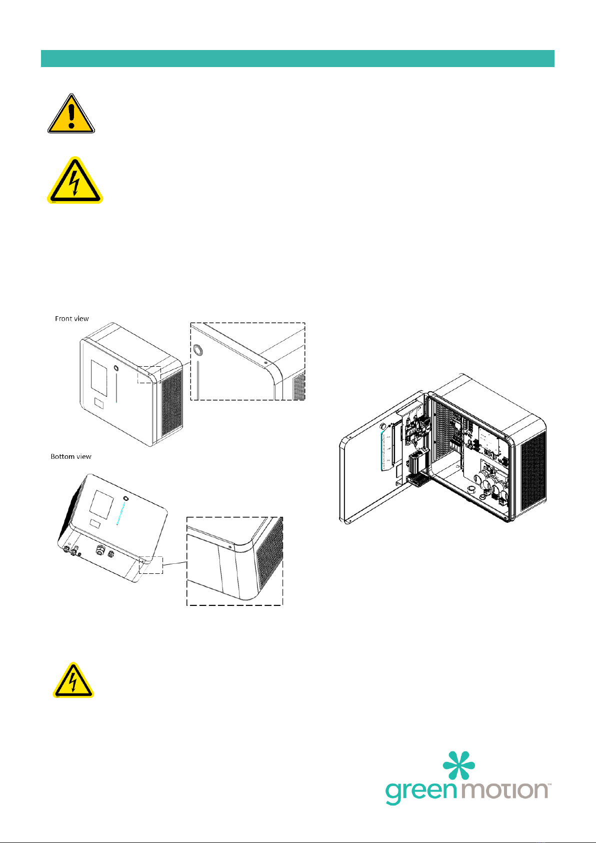
The SKYCHARGE implement’s a 3G/4G/LAN router to enable the IoT connection.
The router is located on the SKYCHARGE door.
Router Configuration
The configuration is performed on the Green Motion Manufacturing Plan
Teltonika RUTX09 modem router configuration
Default settings:
- IP: 192.168.1.1
- User: admin
- Password: admin01
- The router requires a password change during the first start *
(*) Please contact Green Motion SA support for the password.
3G/4G Configuration
Insert the SIM card in the SIM1 port
●Connect a computer and go to the site
http://192.168.52.1(*)
●If a step-by-step configuration menu "Setup Wizard"
appears, you must ignore it and go directly to the
menus described below.
●Go to the Network> WAN menu
●Activate and edit the MOB1S1A1 network
●If necessary, enter the APN and the PIN code of the SIM card (APN: shared.m2m.ch)
●Press Save & Apply
(*) Please contact Green Motion SA support for the password.

SKYCHARGE –TECHNICAL DOCUMENTATION Page 11
LAN Configuration
Connect a computer and go to the site http://192.168.52.1 (*)
●If a configuration step-by-step menu appears, it must be closed.
●Go to the Network > WAN menu
●Activate the WAN network and deactivate the other networks
●Press Save & Apply
oAuthorize the management of the router from the WAN (Only if in a private network)
▪Go to System> Administration> Access control
●Check Enable Remote HTTP and Enable Remote HTTPS
(*) Please contact Green Motion SA support for the password

SKYCHARGE –TECHNICAL DOCUMENTATION Page 12
4USAGE OF THE STATION
4.1 Description of the station
1. Button indicator
2. Touch screen display
3. RFID reader
4. LED display
5. Emergency stop button
To start a charge, simply connect the plane via the GB/T cable. Then press on the screen to charge the plane up to
80% or 100%. In future software development, starting the charge will be possible via an RFID card (offline and
online), via the mobile app (online stations only) or via a SMS (online stations only).

SKYCHARGE –TECHNICAL DOCUMENTATION Page 13
4.2 Charging states
Button indicator
Button
Status display
Comments
No light
Not powered or start-up stage
Green light on
Ready to be use or need user interaction
Blue light on
Charge initialization, vehicle charging, or charge finished
Red light on
Error in charging

SKYCHARGE –TECHNICAL DOCUMENTATION Page 14
LED display
The LED display indicates the charge status.
LED Display
Status display
Comments
Green light on
Ready to be use
Flashing green light
Start-up stage
Breathing green light
Waiting for user interaction
Flashing blue light
Charge start-up stage
Breathing blue light
Vehicle in charge
Blue light on
Vehicle charged
Red light on
Error in charging
No light
Stopped or not powered
50%
100%

SKYCHARGE –TECHNICAL DOCUMENTATION Page 15
Touch screen display
As the touch screen display is the user interface and implements a lot of screen, please take time to read what is
described and write on the screen before to operate.
In this section you will find the information to start your experience.
LED Display
status display
Splash screen
Touch the screen to wake up.
Authentication screen
Before any operation, please ensure that the 4G sign is
colored in blue on the top left corner.
If bar graph is RED, there is no connection to the
server.
By touching the Flag, you can select your language.
Present the RFID badge on the RFID reader to initiate
authentication.

SKYCHARGE –TECHNICAL DOCUMENTATION Page 16
5MAINTENANCE
In order to prevent any technical failure, Green Motion is performing maintenance services. Please
contact Green Motion Support for more information on maintenance contracts.
Electric shock hazard! Please make sure that the main power supply is turned off before trying to
open the charging station. In any case, working under voltage shall be avoided.
CHECK THAT THE CIRCUIT-BREAKERS ARE OPEN ON THE PANEL BEFORE ANY MANIPULATION
5.1 Troubleshooting
Before any troubleshooting action, please carefully observe the led status colour and read with attention the
indication displays on the screen.
The charging station does not
start
-Check the power supply on the electrical panel, switch off and reset the circuit-
breaker to restart it.
The charging station indicates that
the emergency button is pushed
-The emergency button is located underneath the station main case. Turn it for release
until it clicks into open position.
The charging station visual
indicators are red
-Try to disconnect the plane from the charging station and retry
-Check the emergency button, it should be pull out
Antenna bar graph is red
-Check that the connection of the SKYCHARGE to the backend is available / network is
available
Authentication refused
-Check that you are a recognize and authorized user subscribed to the charging point
operator database
-Check that the connection of the SKYCHARGE to the backend is available
The socket visual indicators are
red
-Check the power supply on the electrical panel, switch off and reset the circuit-
breaker to restart it.
The plane is locked to the charging
station
-In some cases, the user must unlock the plug from the plane’s dashboard or using the
key control (long press is sometimes required)
-In case the user is really not able to remove the cable, press the emergency shutdown
to release the cable. The emergency button must then be set back to its initial position
The plane does not charge
-Check the condition of the Cable GB/T.
-Check the power supply on the electrical panel, switch off and reset the circuit-
breaker to restart it.
-Try to start and move the plane, then retry to charge

SKYCHARGE –TECHNICAL DOCUMENTATION Page 17
5.2 Cleaning or replacing the filters
Moving part –Risk of Injury: Please make sure that the fans are turned off and that the station is not
in use during the maintenance operation. Moving fans can be dangerous and cause finger injuries
Filter Maintenance. Please make sure the filters are checked on a yearly basis to ensure they are not
obstructed and working properly. In case of obstruction, filters need to be replaced immediately.
Filters can be replaced. They are accessible as described below.
Using a 2.5 mm hex key, remove the 2 screws attaching each filter cartridge to the unit:
The filters are located inside the filter cartridge. Contact Green Motion support for spare filter parts.
Filter reference is:
GM500075 MZ4-161-397-20-S/290
FIBRES SYNTHÉTIQUES BLANC
ISO COARSE 50% / G4
DIM. 161 X 397 MM
5.3 Support
Green Motion telephone support is available Monday to Friday from 08:00 to 12:00 and from 13:00 to 17:00
(16:00 on Friday) CET
Email: support@greenmotion.ch
Tel: +41 21 544 04 46
Other manuals for PIPISTREL SKYCHARGE
1
This manual suits for next models
1
Table of contents
Other Green motion Batteries Charger manuals