Green motion RANGE XT 22 Guide

TECHNICAL
DOCUMENTATION
NON-CONTRACTUAL PICTURES | DOC. VERSION 16122021
Opening the charging station and any changes to the configuration must be done by a qualified electrician and must comply with local
regulations and laws for safety in the use of electricity. Failure to comply with the regulations in this manual will result in the end the
warranty period.

RANGEXT 22 – TECHNICAL DOCUMENTATION Page 2
CONTENT
1 INTRODUCTION 3
1.1 Technical Specifications 3
1.2 Dimensions and weights 3
2INSTALLATION 4
2.1 Mounting 4
2.2 Site design 8
2.3 Wiring 9
3COMMISSIONING 11
3.1 Opening the Range XT 22 housing 11
3.2 Changing the charging current 12
3.3 Charging station configuration 13
3.4 Emobility Cockpit connection 14
4USAGE OF THE STATION 17
4.1 Description of the station 17
4.2 Sockets and Cables 18
4.3 Charging states 18
5MAINTENANCE 21
5.1 Troubleshooting 21
5.2 Cleaning or replacing the filters 22
5.3Support 23

RANGEXT 22 – TECHNICAL DOCUMENTATION Page 3
1 INTRODUCTION
1.1 Technical Specifications
POWER INPUT
DC RANGE XT EV CHARGER
Input voltage
3 x 400 VAC 50 Hz
Input current
3 x 32 Arms (22 kW)
Power factor
> 0.99
Standby consumption
< 90 W
POWER OUTPUT
Output power
22 kW
Output voltage
500 VDC (extendable to 1000VDC)
Output current 22 kW
55 ADC
Output type
CCS cable (standard) and CHAdeMO cable (optional)
Efficiency
> 96%
Simultaneous charges
1
USER INTERFACE & CONTROL
User interface
Button, charge status indicator, 10-inch touch screen display
Mobile phone app
iOS and Android (online charging station)
Control of access
RFID, App, SMS, Scan & Charge
Network interface
Ethernet cable; 3G/4G
Remote management
Software management system (eMobility Cockpit) (online)
ENVIRONMENTAL
Operating temperature
-25°C to 45°C
Altitude
Up to 2000 m (6500 ft.)
Setting
Wall; Column; indoor or outdoor
Humidity
<95% relative humidity
MECHANICAL
Dimensions
520 x 630x 265mm
Weight
55 kg
Housing material
Stainless steel
Cooling
Fan cooling
Cable length
5 meters (16.5 ft.)
REGULATION
Conformity
IEC 61851-1
Protection rating
IP54
Communication protocol
OCPP 1.6J
Bidirectional
V2G ready
Protection
Over current, under voltage, over voltage, residual current, surge protection, short circuit, over
temperature, ground fault, galvanically insulated
1.2 Dimensions and weights
Width
630 mm
Height
520 mm
Depth
263 mm
Weight
55 Kg

RANGEXT 22 – TECHNICAL DOCUMENTATION Page 4
2 INSTALLATION
2.1 Mounting
Mounting on the wall
Recommended mounting height above: 1600 mm
Paste the 4 seals on the back of the charging station
Fixing with 4 stainless steel screws M6 according to the following diagram and depending on the
material of the wall:
Screw through the charging station. When fixing with the 4 screws M6 do not forget the flat washers:
Drilling hole in the metal enclosure or making any modification not described or
authorized in the present document will end the warranty of the product.

RANGEXT 22 – TECHNICAL DOCUMENTATION Page 5
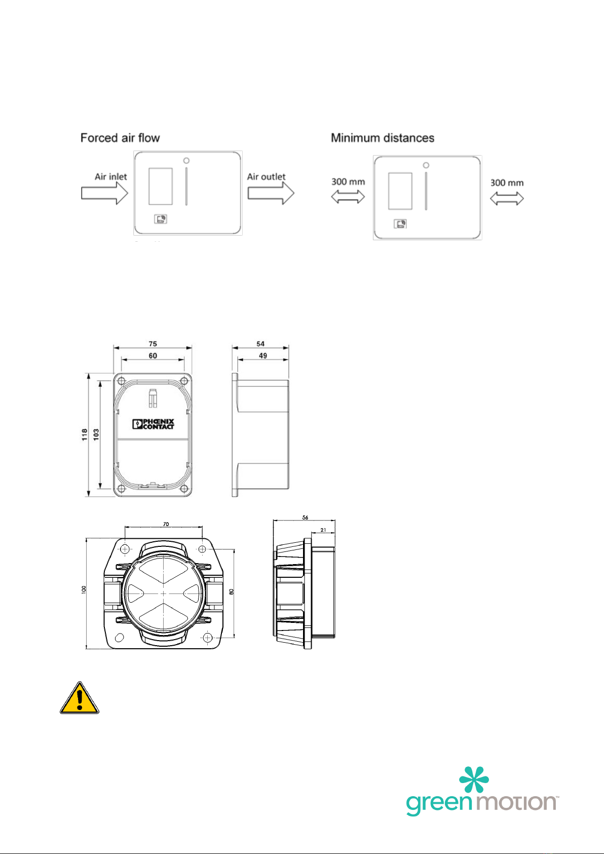
The Range XT 22 has an air inlet on the left side and outlet on the right side. Keep left and right side with
at least 300mm in order to guarantee an unimpeded airflow. If necessary, take precautions to have a free
air flow and to prevent snow or objects from blocking the in- and outlet.
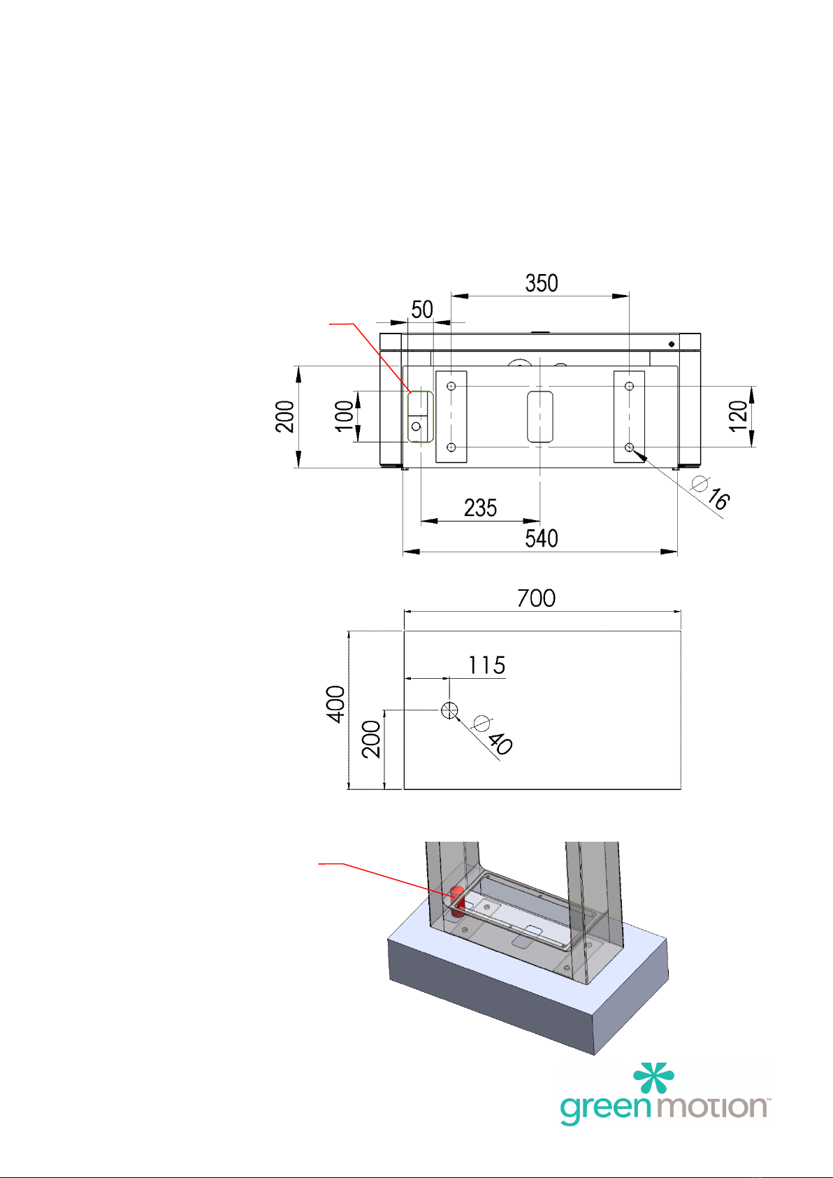
The cable support shall be mounted at a height comprised between 1 and 1.1m from the ground level,
for optimal accessibility.
It can be mounted freely to the right or the left side of the charging station depending upon site
configuration and user preferences, considered the 300mm free space for the air inlet and outlet.
Please take all precautions for the positioning of the socket, mainly in the orientation of the
polarizing slot.

RANGEXT 22 – TECHNICAL DOCUMENTATION Page 6
Mounting on the column (Optional)
Fix the charging station on the column requires a minimum of two people.
Fix the column on the concrete base with 4 threaded rods M10 according to the following diagram. Do
not forget the flat washers.
Electrical introduction is done through the left opening size 100x50mm with 1600 mm cable.
Bottom view:
Concrete base 700 x 400 x 150 mm:
Electrical introduction
Electrical cable

RANGEXT 22 – TECHNICAL DOCUMENTATION Page 7
Front view:
Paste the 4 seals on the back of the charging station
Fix the charging station on the column with 4 stainless steel screws M6x10 and flat washers
Drill 2x Ø7 hole or push the pre-cutting hole under the cabinet and clean the metal shavings
Fix with 2 stainless steel screws M6x10 with 4 serrated lock washers, 4 flat washers and 2 prevailing torque
type hex lock nuts
Please make sure the emergency button is well protected and not damaged during the installation.
Emergency button

RANGEXT 22 – TECHNICAL DOCUMENTATION Page 8
2.2 Site design
A site for Electric Vehicles (EV) equipped with Range XT 22 charging stations can be designed in different
setups. This section is intended to provide some valuable information on the placement of the Range XT
22 charging stations with respect to parking spaces.
Optimal placement
As show in the figure here below we recommend installing the Range XT 22 front and center of the
parking space and each charging station should serve one parking space.
Alternative placements
Range XT 22 Range XT 22 Range XT 22
Range XT 22
Range XT 22
Range XT 22
Range XT 22
1 2 3
Range XT11/22 Range XT11/22 Range XT11/22

RANGEXT 22 – TECHNICAL DOCUMENTATION Page 9
2.3 Wiring
Connect the station to the electrical panel with the following protections:
Model
22 kW
Input voltage
400 VAC
Input current
32 Arms
Power cable min cross section 1
5 x 10 mm2
Power supply terminal block max section
16 mm2
Circuit breaker at panel 2
C40
As the Range XT is connected directly to the Mains Grid, there is no need of Earth Fault Current
Breaker.
1
• These sections must be re-assessed by the installer according to the length.
2
• The Installer must define the types of Circuit breaker.
• The circuit breakers at panel of 40 A and the power cable minimal cross section of 10 mm2is
overvalued in order to ensure the functioning of the charging station with a temperature increase.
NOTE FOR SWITZERLAND
• The NIBT standard does not requires DC terminals to be protected against direct fault currents.

RANGEXT 22 – TECHNICAL DOCUMENTATION Page 10
Circuit diagram
Connection Diagram:

RANGEXT 22 – TECHNICAL DOCUMENTATION Page 11
3 COMMISSIONING
The opening of the charger as well as any configuration changes must be carried out by a
qualified electrician according to the local safety and electrical regulations and laws. Failure
to comply with the regulations in this manual will result in the end the warranty period.
Electric shock hazard! Any operation requiring opening of the main converter box can
lead to electric shock hazards. Please make sure to carefully read instructions. In case of a
doubt, please immediately contact Green Motion support.
3.1 Opening the Range XT 22 housing
Use a TR20 screwdriver to unscrew the 2 screws located on the top and the bottom right side of the
Range XT front door. The front door can be opened sideway.
Electric shock hazard! In case of an operation on the power converter, the operators
shall disconnect the MCB and wait for at least 5min. Before opening the door, operators
shall ensure absence of voltage on the DC-link capacitors.

RANGEXT 22 – TECHNICAL DOCUMENTATION Page 12
3.2 Changing the charging current
Electric shock hazard! Please make sure that the main power supply is turned off before
trying to connect the power to the charging station. In any case, working under voltage shall
be avoided.
The electrical cable must reach the terminal from the left.
The electrical cable and the communication cable can be introduced into the Range XT housing from the
bottom left side (1 & 2) or from the rear left side (3).
The electrical connection is made on the power supply terminals located at the bottom of the charger.
(See in blue circle)
Please measure the rotating field and the line voltage.

RANGEXT 22 – TECHNICAL DOCUMENTATION Page 13
3.3 Charging station configuration
The following configuration are possible via DIP switch on the GMCU MPb board. The board is located
on the door of the converter enclose, in front of the screen.
JP1: CAN Termination
22kW configuration shall only be used on 22kW chargers.
S2
OFF
ON
1
Offline/Online
Offline
Online
2
RFID Reader
No
Yes
3
CAN slave
No
Yes
4
AC/DC
AC
DC
5
CCS Combo
No
Yes
6
CHAdeMO
No
Yes
7
DC 22kW*
No
22kW
8
AC T23
No
Yes
JP1
S2

RANGEXT 22 – TECHNICAL DOCUMENTATION Page 14
3.4 Emobility Cockpit connection
Range XT implement’s a 3G/4G/LAN router to enable the IoT connection.U
The router is located on the Range XT door
Router Configuration
The configuration is performed on the Green Motion Manufacturing Plan
Teltonika RUTX09 modem router configuration
Default settings:
- IP: 192.168.1.1
- User: admin
- Password: admin01
- The router requires a password change during the first start *
*Please contact Green Motion SA support for the password.

RANGEXT 22 – TECHNICAL DOCUMENTATION Page 15
3G/4G Configuration
Insert the SIM card in the SIM1 port
• Connect a computer and go to the site http://192.168.52.1(*)
• If a step-by-step configuration menu "Setup Wizard" appears, you must ignore it and go
directly to the menus described below.
• Go to the Network> WAN menu
• Activate and edit the MOB1S1A1 network
• If necessary, enter the APN and the PIN code of the SIM card (APN: shared.m2m.ch)
• Press Save & Apply
(*) Please contact Green Motion SA support for the password.

RANGEXT 22 – TECHNICAL DOCUMENTATION Page 16
LAN Configuration
Connect a computer and go to the site http://192.168.52.1 (*)
• If a configuration step-by-step menu appears, it must be closed.
• Go to the Network> WAN menu
• Activate the WAN network and deactivate the other networks
• Press Save & Apply
o Authorize the management of the router from the WAN (Only if in a private network)
§ Go to System> Administration> Access control
• Check Enable Remote HTTP and Enable Remote HTTPS
(*) Please contact Green Motion SA support for the password

RANGEXT 22 – TECHNICAL DOCUMENTATION Page 17
4 USAGE
4.1 Description of the station
1. Button indicator
2. Touch screen display
3. RFID reader
4. LED display
5. Emergency stop button
To start a charge, simply connect the car to the appropriate socket. To switch on the Model either via the
button (offline charging station), via the RFID card (offline and online), via the mobile app (online stations
only) or via a SMS (online stations only).

RANGEXT 22 – TECHNICAL DOCUMENTATION Page 18
4.2 Sockets and Cables
The Range XT 22 is available in different configurations depending on the available charging cables.
CCS (EU)
CHAdeMO
Option 1 (standard)
X
Range XT 22
Option 2
X
Option 3
X
X
When you have authenticated on the Range XT 22, for the CHAdeMO plug, you must select the plug
icon on the screen, it is mandatory.
Plug type icon shows as below:
CCS (EU) CHAdeMO
4.3 Charging states
Button indicator
Button
Status display
Comments
No light
Not powered or start-up stage
Green light on
Ready to be use or need user
interaction
Blue light on
Charge initialization, vehicle
charging, or charge finished
Red light on
Error in charging

RANGEXT 22 – TECHNICAL DOCUMENTATION Page 19
LED display
The LED display indicates the charge status.
LED Display
Status display
Comments
Green light on
Ready to be use
Flashing green light
Start-up stage
Breathing green light
Waiting for user interaction
Flashing blue light
Charge start-up stage
Breathing blue light
Vehicle in charge
Blue light on
Vehicle charged
Red light on
Error in charging
No light
Stopped or not powered
50 % of charge 100 % of charge
50 %
100 %

RANGEXT 22 – TECHNICAL DOCUMENTATION Page 20
Touch screen display
As the touch screen display is the user interface and implements a lot of screen, please take time to read
what is described and write on the screen before to operate.
In this section you will find the information to start your experience.
LED Display
status display
Splash screen
Touch the screen to wake up.
Authentication screen
Before any operation, please ensure
that the 4G sign is colored in blue.
If bar graph is RED, there is no
connection to the server
By touching the Flag, you can choose
your language
Present the RFID badge on the RFID
reader to initiate authentication.
This manual suits for next models
2
Table of contents
Other Green motion Batteries Charger manuals