Stationary, Non-Drainable Blade Louver Models8
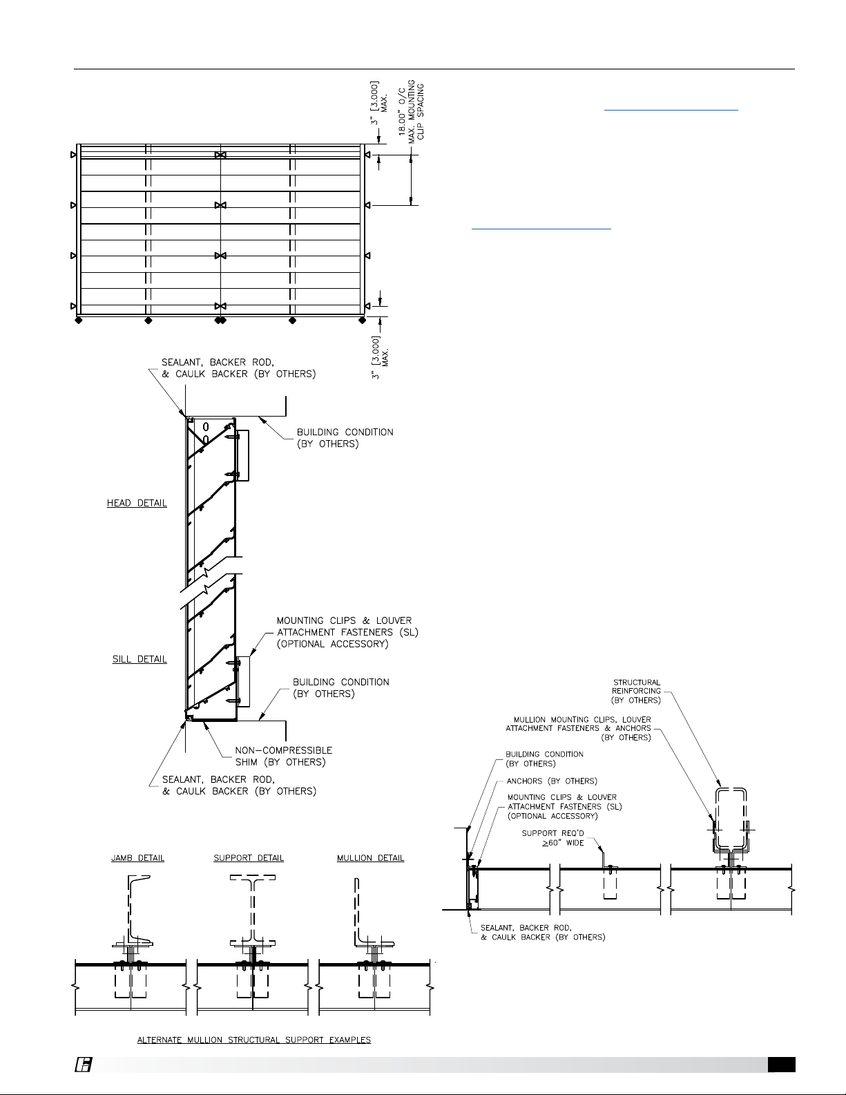
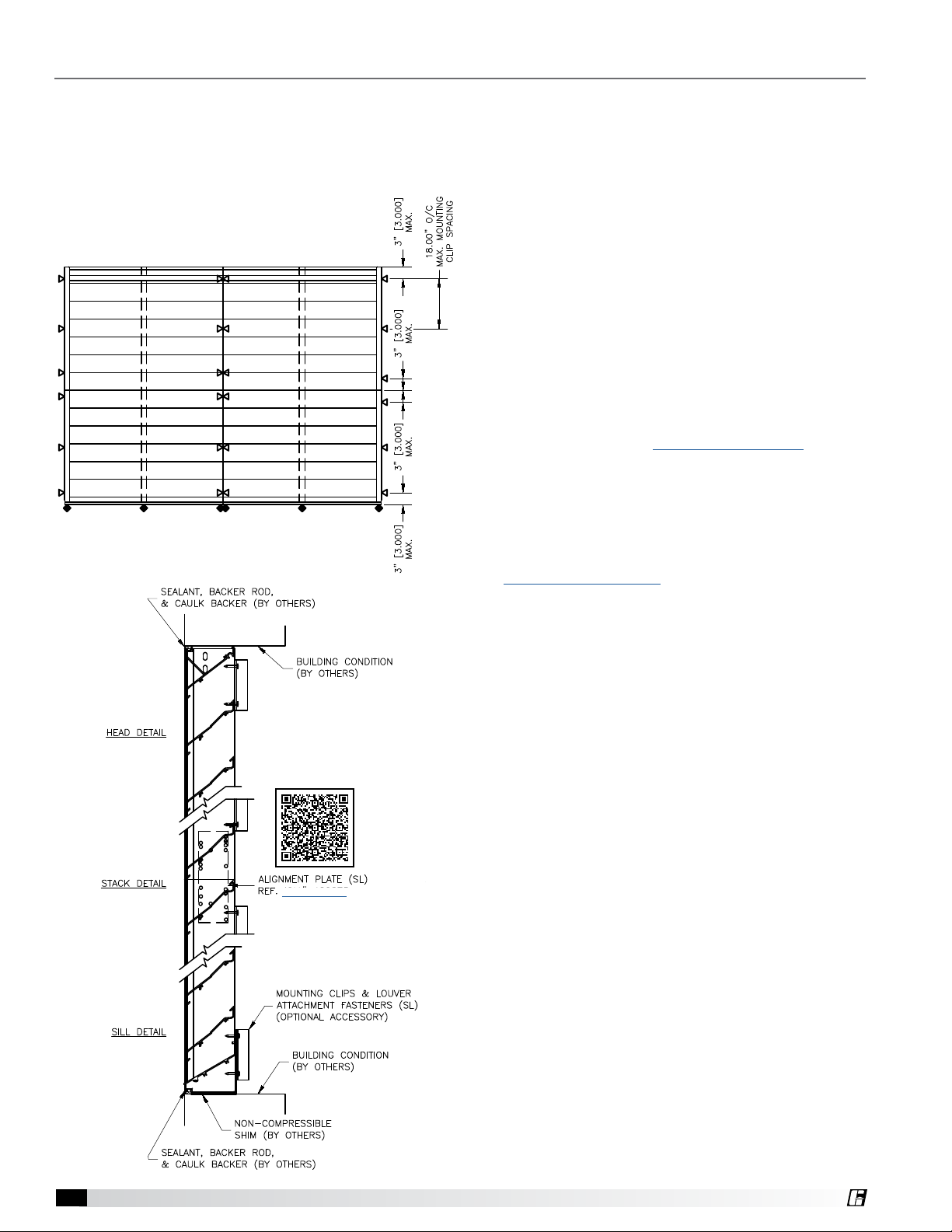
Multiple Section Wide x Multiple Section High Installation
Larger opening sizes require field assembly of multiple louver sections to make up the overall opening size.
Individual louver sections are designed to withstand a 25 psf wind load. Structural reinforcing members
may be required to adequately support and install multiple louver sections within a large opening. Structural
reinforcing members along with any associated installation hardware is not provided by manufacturer unless
indicated otherwise by manufacturer.
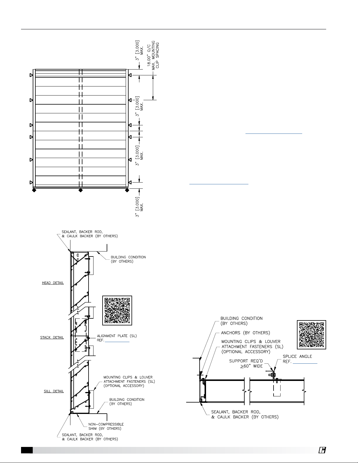
1. Locate the shipped loose Alignment Plates for
the jambs. Following the provided Installation,
Operation, and Maintenance Manual instructions
included with the Alignment Plates, connect the
upper and lower louver sections together.
2. If the louver sections are wide enough to require a
blade support angle, the upper louver section and
lower louver section angles will need to be spliced
together. This can be accomplished by following the
provided Installation, Operation, and Maintenance
Manual instructions included with the shipped loose
Splice Angle kit.
3. Locate the optional extended sill, if provided, and
place in the opening. (Extended Sill Details)
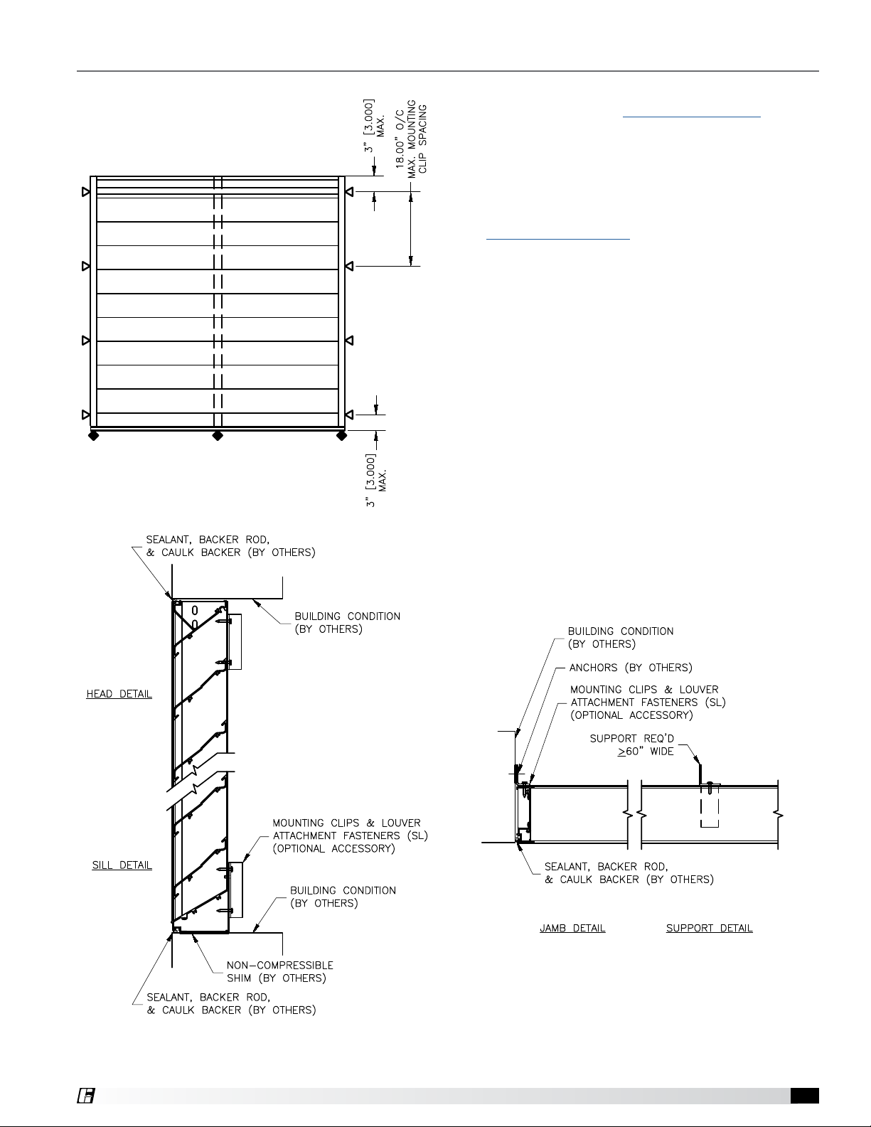
4. Locate mounting angles and fasteners required to
attach the louver to the structure. Clip angles and
fasteners are by others unless the optional mounting
angles have been ordered from manufacturer with
the louvers. Anchors to the structure are by others
and are not manufacturer provided.
(Mounting Clip Details)
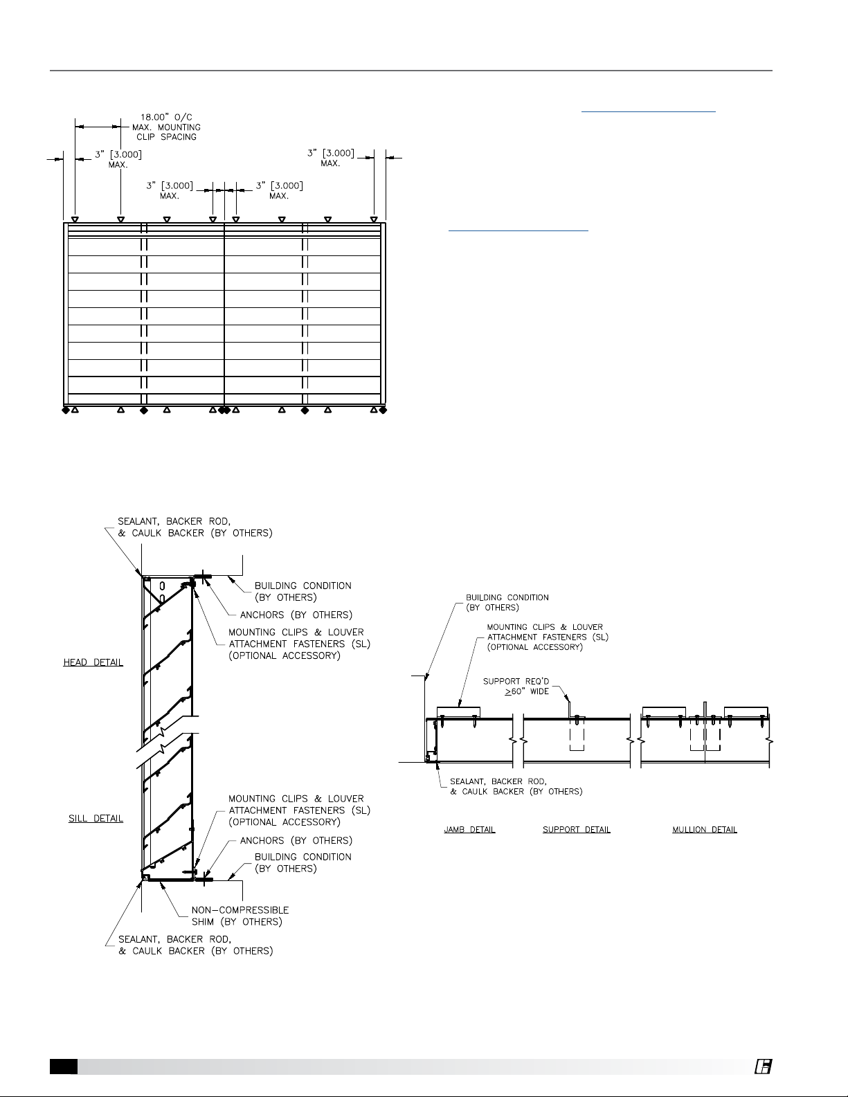
5. Place the combined left louver section assembly (as
viewed from the exterior) in the opening and shim
around the perimeter to maintain proper spacing for
backer rod and caulk joint.
6. Using the appropriate fasteners, secure the
mounting angles to the back of the louver frame at
the perimeter.
7. Ensure the louvers is level and in the correct
location within the opening and secure the mounting
angles to the structure using the correct anchor (by
others) for the building substrate material.
8. Place the next combined louver section to the
right of the first louver section. Shim around the
perimeter to maintain proper spacing for backer rod
and caulk joint. Repeat steps 6-7 above to secure
the louver to the structure.
9. Follow the same procedure for any additional
sections to the right.
10. Additional structural supports (not designed or
provided by manufacturer) may be required and
will need to be installed behind the louver mullions
at this point. The louvers must be secured to the
structural support using the appropriate mounting
angles and fasteners (by others)
11. Once the louver is secured to the structure, install
backer rod and caulk around the perimeter of the
opening at the front of the louver.
Figure 5.1
Figure 5.2
IOM# 482875