Copyright © 2017 Greenheck Fan Corporation
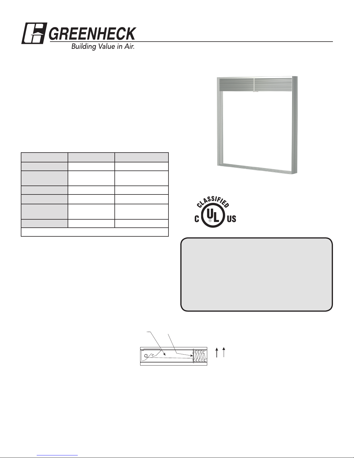
SSFD-150 Rev. 9 December 2017
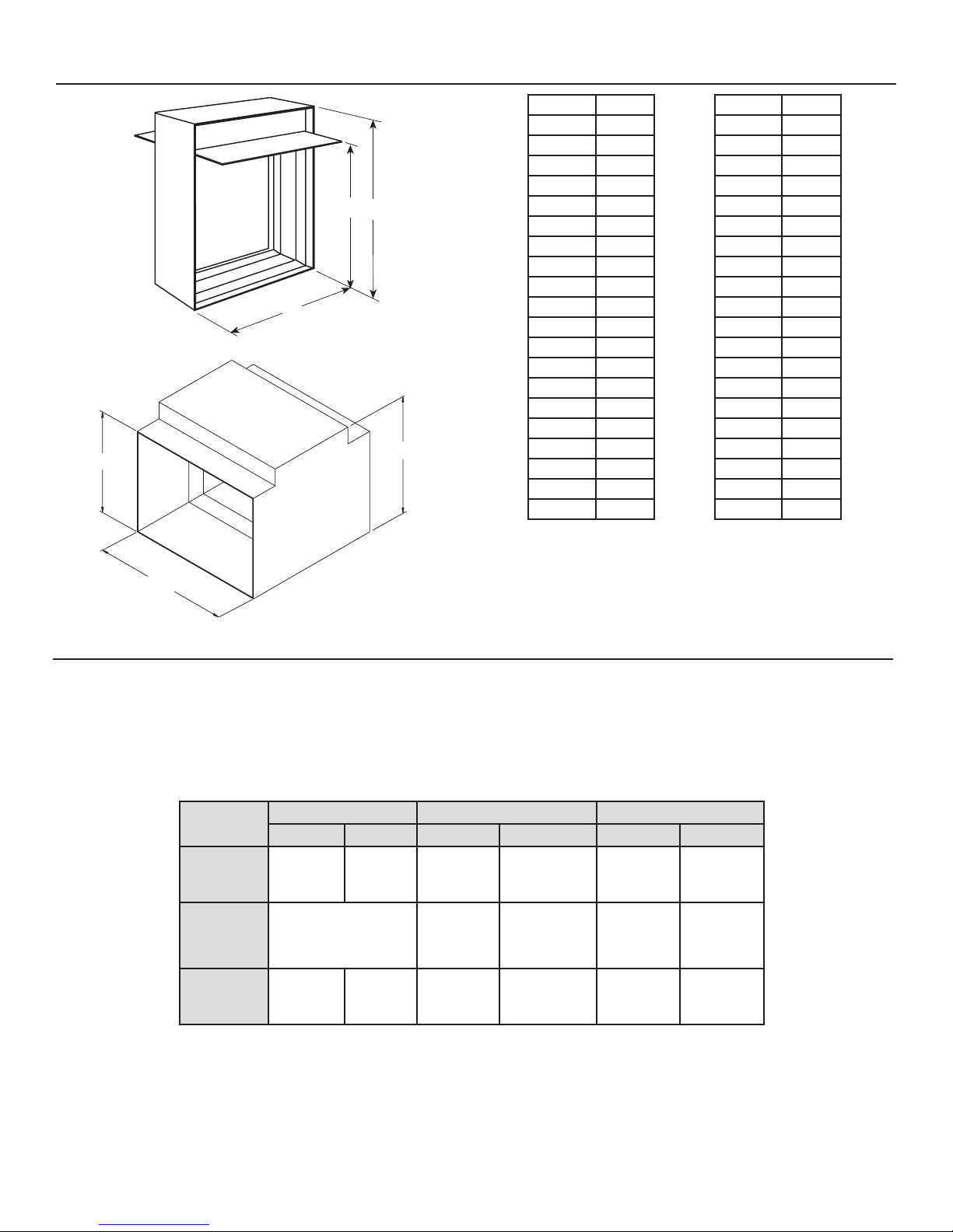
H* or D* O* H* or D* O*
3 (76) 6 (152) 23 (584) 28 (711)
4 (102) 7 (178) 24 (610) 29 (737)
5 (127) 8 (203) 25 (635) 30 (762)
6 (152) 9 (229) 26 (660) 31 (787)
7 (178) 10 (254) 27 (686) 32 (813)
8 (203) 11 (279) 28 (711) 33 (838)
9 (229) 12 (305) 29 (737) 34 (864)
10 (254) 13 (330) 30 (762) 36 (914)
11 (279) 14 (356) 31 (787) 37 (940)
12 (305) 15 (381) 32 (813) 38 (965)
13 (330) 16 (406) 33 (838) 39 (991)
14 (356) 18 (457) 34 (864) 40 (1016)
15 (381) 19 (483) 35 (889) 41 (1041)
16 (406) 20 (508) 36 (914) 42 (1067)
17 (432) 21 (533) 37 (940) 44 (1118)
18 (457) 22 (559) 38 (965) 45 (1143)
19 (483) 23 (584) 39 (991) 46 (1168)
20 (508) 24 (610) 40 (1016) 47 (1194)
21 (533) 26 (660) 41 (1041) 48 (1219)
22 (559) 27 (686) -
Sizing Data SSFD-150 Type CR, CO, C & R cont...
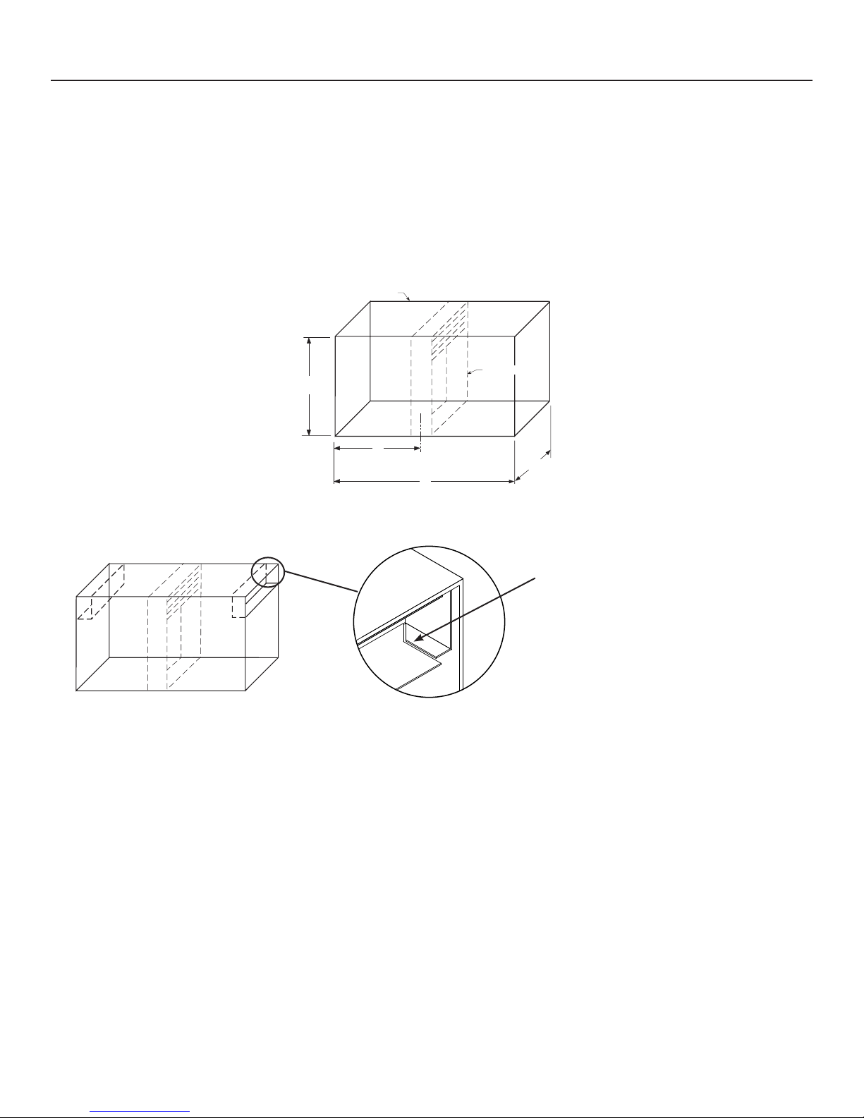
C, CO, CR transitions are positioned 1 in. (25mm)
from bottom of sleeve
O*
H*
Type C
W*+2
W*
O*
H*
Type CO
W*+2
W*
D*
Type CR
O*
D*+2
* Dimensions are inches (mm). These dimensions are furnished
approximately 1⁄4in. (6mm) undersize, except round and oval dimensions
(D, H, W) are approximately 1⁄8in. (3mm) undersize. (All ‘H’ dimensions
larger than single section height are two sections high. Refer to chart.)
Multi-Section Limitations
Maximum height is 34" when width is gr eater than 94" and less than or equal to 118".
3
2 Multi-Section Limitations
Maximum height is 42" when width is 94" or less.
Maximum Single Section Dimensions
1
94"
max.
41"
max.
94"
max.
41"
max.
118"
max.
34"
max.
118"
max.
34"
max.
Type CType CO
Type CType CO
4 Multi-Section Limitations
Maximum height is 69" when width is equal to or less than 74”. (Vertical mullion pr ovided on
dampers over 35” wide and 42” high.)
72"
max.
69"
max.
Type CType CO
41 in. (1041mm)
max.
46 in.
41 in.
(1041mm)max.
Type C Type CO
72"
max.
69"
max.
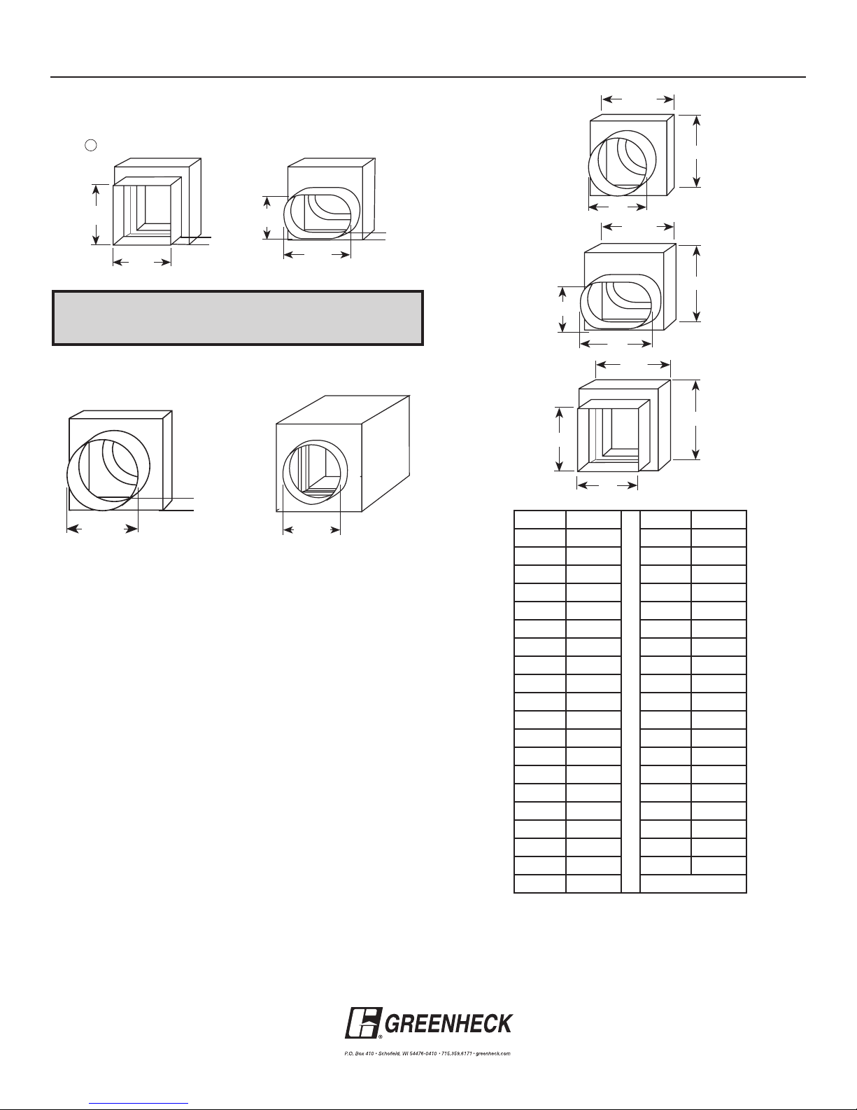
Reinforcement
Rods
(1168mm)
46 in.
max.
(1168mm)
1 in. (25mm)
off bottom
1 in. (25mm)
off bottom
3 in. (76mm) min.
41 in. (1041mm) max.
1 in. (25mm)
off bottom
Type CR
46 in. (1168mm) max.
3 in. (76mm) min.
Type R
* All multiples section dampers, with transitions, will include a factory
installed sleeve.