Greenhouse People HE-BLE User manual

8’ Wide
ASSEMBLY INSTRUCTIONS
ISSUE: 4
Model
HE-BLE

2
Website: www.greenhousepeople.co.uk E-mail: info@thegreenhousepeople.co.uk
Dear Customer,
Thank you for ordering your new greenhouse from us. We hope you find these in-
structions along with each member of 'The Greenhouse People' team helpful and in-
formative.
Please read all information before you begin and take care to read all instructions it
will save you a lot of time and frustration later on. This instruction manual is also
available online at www.greenhousepeople.co.uk in our technical help section where
you can zoom in on all the pictures and text and reprint a copy if your manual gets left
out in the rain.
If you want any more advice, you can always give us a ring on 01782 388811.
Once again, thank you for your order and all the very best with your greenhouse.
Yours sincerely,
The Greenhouse People
www.greenhousepeople.co.uk
P.S. Please do send us a photograph of your finished greenhouse. We’re always
interested to see how you’ve gone on. Send to: info@greenhousepeople.co.uk

3
CONTENTS
Page
4 - 6 COMPONENTS AND FITTINGS
7 INCH — MM CONVERSION CHART
8 -10 BASE PREPARATION
11SAFETY
12 GENERAL ADVICE
13 - 15 SIDE ASSEMBLY
16 -17 REARASSEMBLY
18 -21 FRONTASSEMBLY
22 - 23 DOOR ASSEMBLY
24 - 29 ROOF VENT ASSEMBLY
26 -29 MAIN BUILDING ASSEMBLY
30 -31 LOUVRE ASSEMBLY
32 GLASS PLAN
33GLAZING
34 -39 FINAL FIXING
NOTE: ALL DIAGRAMS ARE CODED. IF THE DIAGRAM IS VIEWED FROM THE OUTSIDE
THE ALPHABETICAL REFERENCE BOX IS BLACK WITH WHITE LETTERING:
IF THE DIAGRAM IS VIEWED FROM THE INSIDE THEN THE REFERENCE BOX IS CLEAR
WITH BLACK LETTERING:

4
COMPONENTS & FITTINGS
Bracing, Diagonal - 303 Bracing,
Purlins - 308 & 314
Bracing, Flat - 315Base Bracket - 300
Cill, Side -
350,351,352,353 & 354
Door Middle - 373Cill, Front & Rear - 333
Door Stop - 400 Door Track - 403Door Stiles (female) -
377,379
Door Track, Main
Support - 406
Glazing Bar, Roof
Corner Left - 410
Glazing Bar, Roof
Corner Right - 416
Door Track Support
Bracket - 404
Door Runner - 375
Door Stile (male) - 381

5
COMPONENTS & FITTINGS
Glazing Bar, Front &
Rear - 438, 449
Glazing Bar, Roof &
Side - 444 & 447
Gutter - 461, 462, 463 &
464
Ridge Plate - 500Ridge - 481, 482, 483 &
484
Vent Slam Bar - 542 Vent Top - 543
Edging Strip - 558
[Plastic]
Vent Side - 541
Glass Jack - 557
[Plastic]
Glazing Separator - 559
[Plastic]
Glazing Bar, Side
Corner - 430
Vent Bottom - 540
Door Track
Vertical Support - 508
Threshold - 526

6
COMPONENTS & FITTINGS
Door Bottom - 707
Glazing Rubber - 570
Vent Peg - 709
Bolt, Hex Head, M4
25mm - 575
Bolt, Square Head, M6
10mm - 576
Glazing ‘W’ Clip - 577
Nut, M4 - 578
Nut, M6 - 579
Bolt, Square Head, M6
15mm - 588
Screw, Countersunk, M4
10mm - 587
Door Stop Bung - 560
[Rubber]
Cantilever, Ridge - 600
Cantilever, Eaves - 601
Screw, Self Tapping,
M4.2 19mm - 583
Hanging Basket
Bar - 685, 687,688,689
& 690
Push-in
Capping - 821-824
[Plastic]
Door Top - 708
Nut Cap, M6 - 580
[Plastic]
USE MEASUREMENTS TO HELP YOU IDENTIFY PARTS

7
INCH — MM CONVERSION CHART
Inch mm Inch mm Inch mm Inch mm Inch mm Inch mm Inch mm
1 25.4 2' 609.6 4' 1219.2 6' 1828.8 8' 2438.4 10' 3048 12' 3657.6
2 50.8 2'1 635 4'1 1244.6 6'1 1854.2 8'1 2463.8 10'1 3073.4 12'1 3683
3 76.2 2'2 660.4 4'2 1270 6'2 1879.6 8'2 2489.2 10'2 3098.8 12'2 3708.4
4 101.6 2'3 685.8 4'3 1295.4 6'3 1905 8'3 2514.6 10'3 3124.2 12'3 3733.8
5 127 2'4 711.2 4'4 1320.8 6'4 1930.4 8'4 2540 10'4 3149.6 12'4 3759.2
6 152.4 2'5 736.6 4'5 1346.2 6'5 1955.8 8'5 2565.4 10'5 3175 12'5 3784.6
7 177.8 2'6 762 4'6 1371.6 6'6 1981.2 8'6 2590.8 10'6 3200.4 12'6 3810
8 203.2 2'7 787.4 4'7 1397 6'7 2006.6 8'7 2616.2 10'7 3225.8 12'7 3835.4
9 228.6 2'8 812.8 4'8 1422.4 6'8 2032 8'8 2641.6 10'8 3251.2 12'8 3860.8
10 254 2'9 838.2 4'9 1447.8 6'9 2057.4 8'9 2667 10'9 3276.6 12'9 3886.2
11 279.4 2'10 863.6 4'10 1473.2 6'10 2082.8 8'10 2692.4 10'10 3302 12'10 3911.6
1' 304.8 2'11 889 4'11 1498.6 6'11 2108.2 8'11 2717.8 10'11 3327.4 12'11 3937
1'1 330.2 3' 914.4 5' 1524 7' 2133.6 9' 2743.2 11' 3352.8 13' 3962.4
1'2 355.6 3'1 939.8 5'1 1549.4 7'1 2159 9'1 2768.6 11'1 3378.2 13'1 3987.8
1'3 381 3'2 965.2 5'2 1574.8 7'2 2184.4 9'2 2794 11'2 3403.6 13'2 4013.2
1'4 406.4 3'3 990.6 5'3 1600.2 7'3 2209.8 9'3 2819.4 11'3 3429 13'3 4038.6
1'5 431.8 3'4 1016 5'4 1625.6 7'4 2235.2 9'4 2844.8 11'4 3454.4 13'4 4064
1'6 457.2 3'5 1041.4 5'5 1651 7'5 2260.6 9'5 2870.2 11'5 3479.8 13'5 4089.4
1'7 482.6 3'6 1066.8 5'6 1676.4 7'6 2286 9'6 2895.6 11'6 3505.2 13'6 4114.8
1'8 508 3'7 1092.2 5'7 1701.8 7'7 2311.4 9'7 2921 11'7 3530.6 13'7 4140.2
1'9 533.4 3'8 1117.6 5'8 1727.2 7'8 2336.8 9'8 2946.4 11'8 3556 13'8 4165.6
1'10 558.8 3'9 1143 5'9 1752.6 7'9 2362.2 9'9 2971.8 11'9 3581.4 13'9 4191
1'11 584.2 3'10 1168.4 5'10 1778 7'10 2387.6 9'10 2997.2 11'10 3606.8 13'10 4216.4
3'11 1193.8 5'11 1803.4 7'11 2413 9'11 3022.6 11'11 3632.2 13'11 4241.8
Inch mm Inch mm Inch mm Inch mm Inch mm Inch mm
14' 4267.2 15' 4572 16' 4876.8 17' 5181.6 18' 5486.4 19' 5791.2
Inch mm 14'1 4292.6 15'1 4597.4 16'1 4902.2 17'1 5207 18'1 5511.8 19'1 5816.6
0.25" 6.35 14'2 4318 15'2 4622.8 16'2 4927.6 17'2 5232.4 18'2 5537.2 19'2 5842
0.5" 12.7 14'3 4343.4 15'3 4648.2 16'3 4953 17'3 5257.8 18'3 5562.6 19'3 5867.4
0.75" 19.05 14'4 4368.8 15'4 4673.6 16'4 4978.4 17'4 5283.2 18'4 5588 19'4 5892.8
1" 25.4 14'5 4394.2 15'5 4699 16'5 5003.8 17'5 5308.6 18'5 5613.4 19'5 5918.2
14'6 4419.6 15'6 4724.4 16'6 5029.2 17'6 5334 18'6 5638.8 19'6 5943.6
14'7 4445 15'7 4749.8 16'7 5054.6 17'7 5359.4 18'7 5664.2 19'7 5969
14'8 4470.4 15'8 4775.2 16'8 5080 17'8 5384.8 18'8 5689.6 19'8 5994.4
14'9 4495.8 15'9 4800.6 16'9 5105.4 17'9 5410.2 18'9 5715 19'9 6019.8
14'10 4521.2 15'10 4826 16'10 5130.8 17'10 5435.6 18'10 5740.4 19'10 6045.2
14'11 4546.6 15'11 4851.4 16'11 5156.2 17'11 5461 18'11 5765.8 19'11 6070.6
20' 6096

8
BASE PREPARATION
You have quite a choice in terms of the style of base that you can prepare. The most important
objective is that it is level. The different styles of bases that we recommend are as follows:
Note:Your greenhouse size is only nominal, for example a 6 X 8 greenhouse is not
exactly 6’ by 8’! It will actually be a few inches bigger. So be careful when building
your base as mistakes on the size of your base are difficult to correct later. Also we
don’t recommend building your greenhouse directly onto soil.
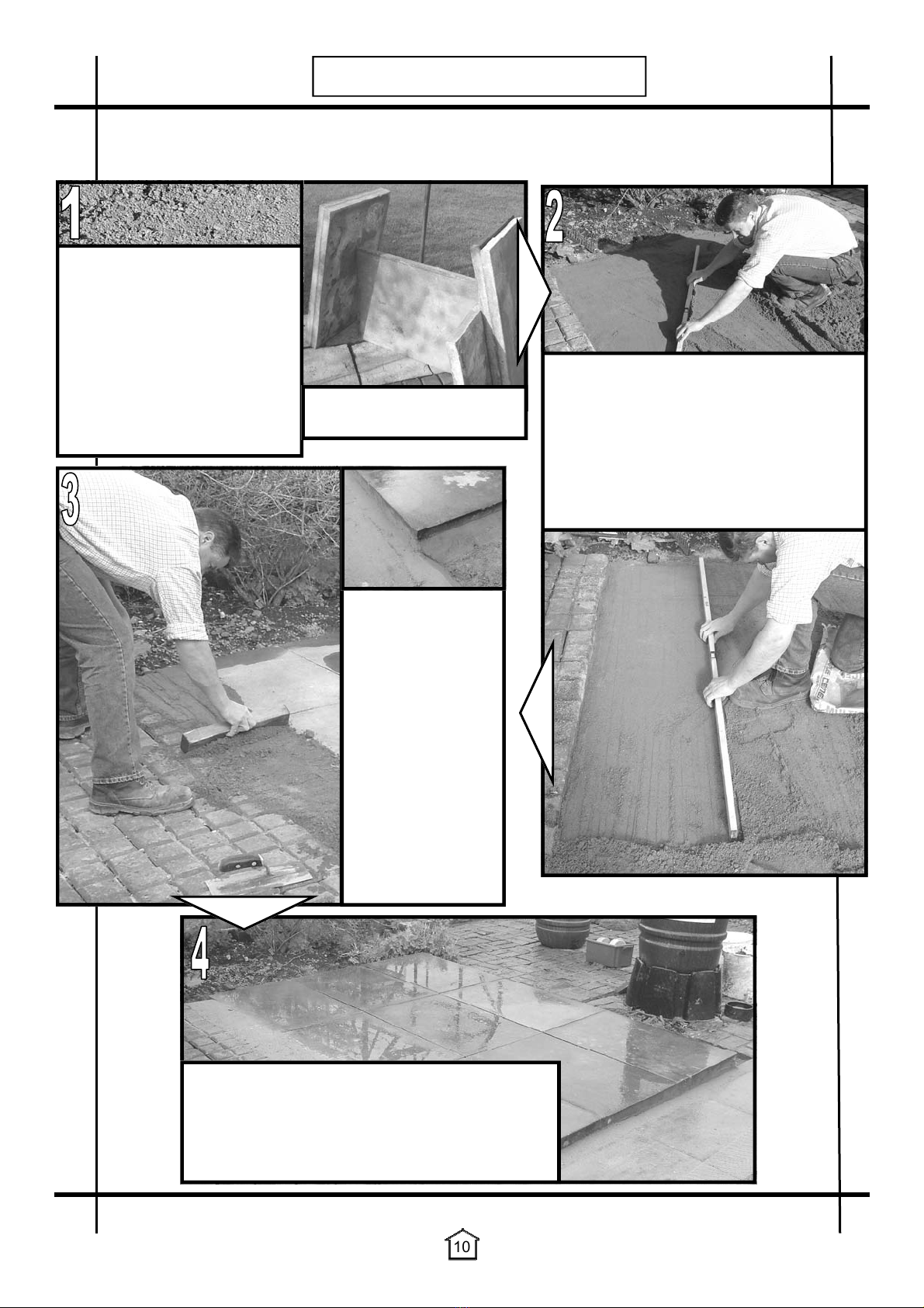
1. Slabs - Level paving slabs are ideal for a greenhouse base. Make sure the area of
slabs is either the same size or larger than the footprint of the greenhouse. Slabs are
also good for drainage because of the joints between them. If you put a polythene
sheet or similar barriers underneath, this could prevent drainage. (See page 10 for a
quick guide to laying slabs).
You can also lay your slabs out as a perimeter around the edge of the building with a
path up the middle if you want to grow directly from the soil.
2. Concrete Plinth - This is a simple footing around the edge of the greenhouse. You
can do this by digging a small trench about 4-6” deep by 6” wide. As with all bases
ensure that it is level along the length as well as side to side. If you don’t have a long
level then you could use a long bar or straight piece of wood under your level to get a
more accurate reading. This is probably the cheapest and easiest base to build
which enables you to have soil inside so that you can grow straight from the ground.
3. Solid Concrete - This type of base is good from a structural point of view as you can
get good fixings. It is also fine as far as drainage is concerned as long as the
concrete is not sealed, painted or laid on a membrane.
Ways of increasing drainage are: When laying the concrete you could lay Aco drive
drains to take surface water away or if the concrete is already laid you could simply
drill through the concrete and create soakaways.
4. Brick Base - This is the traditional greenhouse base. It is usually 1 or 2 courses high
but can be higher if required. This is a much more costly and difficult base to install.
This is because you need to make a concrete footing first, then you need to lay the
courses of bricks to the millimetre so that they fit the cill of the greenhouse perfectly.
However it does have an advantage, the cill overlaps the brick edge minimising water
flow under the cill, which is important if you need to control the humidity and are using
a de-humidifier etc.
Important: Always use a completely solid engineering brick for the top layer with no
holes or frogs (such as Staffordshire Blue). This is because you’ll need to anchor
your greenhouse down by drilling and screwing into the bricks and if they have holes
in then this is extremely difficult. If you are doing more than one course then you can
use bricks with holes or frogs lower down where it will not matter.
See page 9 for external dimensions.
Two different styles of base that we don’t recommend:
1. Block Paving - This is not an ideal base for a greenhouse. This is because when you
screw your greenhouse down you will only be screwing into loose blocks, which will
not be a strong enough fixing.
2. Tarmac - Again not ideal because of the anchoring problems, and it is much harder to
get a level surface. However if you do want to put your greenhouse on tarmac, then
the way to anchor it will be as on soil. You can dig out spade width holes where each
base bracket will situate and fill these with concrete, let it set, then when your green-
house is in position you can screw into the concrete.

9
BASE PREPARATION
The following table gives the external dimensions for a brick base. Look for your building
size in the left hand column and read across for the width and length.
The dimensions allow the lips of the cills to overhang. This helps prevent water running
back into the greenhouse.
When building your base make sure the diagonal measurements are equal.
WIDTH
LENGTH
DIAGONALS
BRICK BASE
Size
Width Length
mm mm
8 X 6 2575 1994
8 X 8 2575 2614
8 X 10 2575 3234
8 X 12 2575 3854

10
BASE PREPARATION
A quick guide to laying down slabs suitable for any garden structure.
Please read ALL before you begin.
Use a long spirit level (or shorter level on a
straight plank) to drag out the sand / cement
mixture until it is perfectly level. Start at one
corner and work away from that point drag-
ging and tapping down as you go. When
you have levelled the sand / cement mix you
can lay your slabs directly onto the mixture.
You may need to give each slab a tap to
make the top edges line up perfectly flush.
Finishing off the
edges of your slabs
with a slightly
stronger mix of sand
and cement will give
a much neater finish.
Simply use a float to
smooth the edges.
Use a watering can
to dampen the slabs
at the end to remove
any cement dust and
to dampen the sand
and cement below
the slabs slightly.
We recommend that you lay
paving slabs onto a dry mixture
of sharp sand and cement. A
ratio of 6:1 would be ideal. We
recommend using a 2” thick slab
rather than a 1” or 1½” as you will
get a better fixing with a thicker
slab.
Please note: This slabbing tech-
nique should only be carried out
on a dry day.
Slabs, ideally 3' x 2',
2" thickness.
These slabs have been laid for a 5' x 8' greenhouse.
When making a slab base like this you must make it
larger than your greenhouse to ensure that it will
easily fit. It is a good idea to have some space
around any garden structure enabling cleaning and
general maintenance access.

11
SAFETY
Some of the components in this kit may cause injury if not used sensibly. When handling
any of the metal components and during glazing please take care and wear gloves,
goggles and ear protectors when you judge necessary.
Do not assemble the frame in high winds.
Children should not play near glass greenhouses.
REMEMBER: Glass is fragile, handle with extreme care!
Do not push or lean on the glass panels.
Be careful when using agricultural chemicals such as fertilisers, fungicides and insecticides
etc. in the greenhouse. Do not use chemicals that are for outside use only. Always read the
labels carefully.
Do not latch the door when anybody is inside the greenhouse.
Use extra care when moving heavy or awkward objects such as tables, poles, internal
frames etc. within or near the greenhouse.
Do not place your greenhouse in vulnerable locations such as under trees, in playing areas,
etc.
Be aware of the increased temperature in a greenhouse on a sunny day.
Do not keep pets or other animals in a greenhouse.
When cleaning glass, do not exert too much pressure.
Do not keep petrol or petrol machinery in a greenhouse.
Tou gh en ed G la ss
VERY IMPORTANT INFORMATION
Please take extra CARE handling toughened glass. It is extremely vulnerable to BREAKAGE at the edges and in
particular, the CORNERS. When you are MOVING it, please take care not to brush the EDGES of the glass
against concrete etc.. as it can SHATTER or BREAK very easily. Likewise, it should ALWAYS be stacked on
wooden bearers, or cardboard, or carpet, or anything to avoid direct contact with a hard floor.
Once the glass is installed into the frame the whole structure becomes much more RIGID.
The toughened glass in particular is very resilient to face-on DAMAGE.
If you are unsure about anything to do with glazing your greenhouse please ring us on 01782 388811.
See also information on page 32-33.
BEWARE OF
SHARP EDGES

12
GENERAL ADVICE
Preparation and things to consider:
Bear in mind that constructing your greenhouse can take some time, you may need to leave it
and come back to it.
The more space available in which to work the better, a large clean,clear garage floor is ideal
or a flat lawn area.
Tidy your work space prior to assembly. This will reduce the chances of loosing any of the
smaller components. It is a good idea to find a tub for all your nut and bolts etc…
When building your own brick/concrete/slab foundations ensure that they are level and square
and built to the correct outside measurements otherwise your frame will not be true and the
glass will not fit.
Be sure that all four sides of the constructed greenhouse are square before installing glass, and
do not install the glass until the greenhouse is in its permanent location.
Anchoring down your greenhouse is the final stage of construction (including glazing). The
greenhouse frame must be anchored to a permanent foundation. This will not only help secure
it against powerful winds, but will help prevent breakage of the glass caused by the freezing and
thawing process of the earth.
Organising your components:
On opening your main greenhouse box DO NOT UNWRAP any of the
labelled bundles until they are required. Be CAREFUL not to mix-up
any of the bundles.
Assess each component in accordance with the parts list in the manual.
Separate like from like components.
If your greenhouse is a painted one there maybe a few 3mm holes in the
ends of some bars. These are jig holes used for painting and have no
bearing on construction.
If you are unsure what a component is try checking the length against
the parts list inside the box.
Tools advice:
You will find a tool kit supplied. This consists of: A pair of gloves, a
10mm spanner, a 10mm spinner and a Philips screwdriver. Other tools
that may be required are shown in the picture (top right).
You will also find a tube of silicone and a silicone gun in the box. This
can be used throughout the greenhouse to stop any leaks.
Using the manual:
Read the information relevant to each stage of construction immedi-
ately before you begin. Study each drawing carefully before you
begin each stage of construction.
Glazing preparation:
WD40 or a similar product can be sprayed into the glazing
channels to make it much easier to insert the glazing rubber.
All rubber should be added to the glazing channels PRIOR to
any assembly.

13
SIDE ASSEMBLY
1. Slide the glazing rubber into the channels of the glazing
bars and trim to correct length before assembly.
2. Lay out the pieces on the ground as though you were standing
inside the greenhouse, i.e. with the gutter and cill facing
downwards and the bolt channels of the glazing bars upwards.
3. Slide a 10mm bolt into the top of each end of the glazing bar
(Diagram bottom right). An extra bolt will have to be fed into
each channel (Diagram D, Page 15) to accommodate your ex-
tra strengthening cantilever bracings or anything else that may
require extra bolts (e.g. a shelf). Slide longer 15mm bolt into
the bottom of each glazing bar so a base bracket can be
attached at a later stage.
4. Fix the cill to the middle glazing bar by pushing the 15mm bolt through the hole in the cill
unit and lightly tighten.
5. Correctly position the cill on the outermost glazing bars by pushing the 15mm bolts through
the holes in the cill, now place the base brackets followed by the diagonal bracings on the
same bolts so they point outward towards the ends of the gutter and lightly tighten the nuts
(Diagram C, Page 15).
6. On buildings larger than 6’ long you will need to attach
additional glazing bars to the cill in the same way as step 5.
7. Attach the gutter to the glazing bars in the same manner as
step 4 and lightly tighten.
8. Attach the other ends of the braces to the hole in the gutter
approximately 100mm from the end. Put the nuts on the bolts
and lightly tighten.
9. Do the same with the other side frame assembly.
10. Make sure that the glazing bars reach both the cill and the gut-
ter in each case.
11. Finally tighten all nuts.
447
570
447
576
EXTERNAL VIEW
570
Part Name Part Length 8 X 6 8 X 8 8 X 10 8 X 12
No. mm
Base bracket 300 - 2 4 4 6
Bracing, diagonal - 6' & 8' W 303 1,742 4 4 4 4
Cill, side 6' L 351 1,888 2 - - -
Cill, side 8' L 352 2,508 - 2 - -
Cill, side 10' L 353 3,128 - - 2 -
Cill, side 12' L 354 3,748 - - - 2
Glazing bar, side 447 1,670 4 6 8 10
Gutter 6' L 461 1,888 2 - - -
Gutter 8' L 462 2,508 - 2 - -
Gutter 10' L 463 3,128 - - 2 -
Gutter 12' L 464 3,748 - - - 2
Bolt, square head - 10mm M6 576 10 12 16 20 24
Bolt, square head - 15mm M6 588 15 4 6 8 10
Nut - M6 579 - 16 22 28 34
Nut caps 580 - 16 22 28 34
INTERNAL VIEW

14
SIDE ASSEMBLY
447447
303
354
462
463
464
303
353
352
351
461
461
351
6’ LONG
8’ LONG
10’ LONG
12’ LONG
6’ LONG
EXAMPLE
A
B
C
D

15
SIDE ASSEMBLY
303
461
461
447
447
447
303
351
588
A
B
D
C
576
576
300
576

16
REAR ASSEMBLY
1.Slide the glazing rubber into the channels in the glazing bars and corner bars. Do not put
glazing rubber into the middle slots of the corner bars (see diagram
on the right).
2.Lay out the frame as though you were standing on the inside i.e.
with the bolt slot uppermost.
The roof corner bars are mitred at one
end whereas the side corner bars are not. The bolt slot is on the inside
and faces inwards during initial construction.
3.Slide a 10mm (576) bolt into the bolt channels of each roof corner bar
and put a nut on, finger tighten 50mm (2") from the top (Diagram F).
These will be used later in the assembly. On the side corner bars, the
bolt channel that attaches to the flange on the roof corner bars, needs a
longer 15mm bolt at the top so that the purlin and diagonal bracing can
be fixed by the same bolt (Diagram bottom right). Now slide up from the
bottom of the bar an extra 10mm bolt in the bolt channel for the second
rear purlin leaving it without a nut. You also need to slot a 15mm bolt in
each bolt channel 50mm (2”) from the bottom so a base anchor bracket can be attached at a later
stage when fixing the greenhouse to the ground. The roof corner bars 410 & 416 also need two
extra 10mm bolts sliding into the channel, this is to attach the hanging basket rail at a later stage
(Marked ‘@’ on page 17 and 19).
4.Bolt the square end of the roof corner bar onto the side corner bar with the diagonal bracing and
the rear purlin on the same bolt, lightly tighten the nuts (Diagram E).
5.Now secure the ridge plate by inserting bolts through the "plate" and into the holes punched in the
flange of the roof corner bar, at the apex (Diagram F).
6.Attach the rear cill to the side corner bars by using one of the 15mm bolts
inserted in “step 3”. Loosen the bolt and drop it into the slot in the cill
(Diagram G).
7.Insert rubber into the three rear glazing bars and then attach to the cill by
slotting a 15mm bolt into the bolt channel of the glazing bars and locating
it with the punched holes in the cill. Before securing the nuts attach the
diagonal bracings to the two outer bars using the same bolts (Diagram H).
8.Slide three 10mm bolts into the bolt channel at the top of the three rear
glazing bars, the first bolt is to attach the lower rear purlin, the second bolt
is to attach the top purlin and the third bolt attaches the outer two glazing
bars to the roof corner bars, do this by inserting the bolt through the
punched hole in the flange of the roof corner bars. The middle glazing
bar attaches to the ridge plate using the hole in the middle of the plate.
9.Check that all angles between the cill and the vertical members are at right angles and that the
glazing bars are tight into the cill at the bottom (Key point). Finally tighten all nuts.
430
570
430
588576
EXTERNAL VIEW
*When viewed from the outside.
Part Name Part Length Qty
No. mm Required
Base bracket 300 - 4
Bracing, flat 315 1,779 2
Bracing, rear purling - 8' W 318 2,496 2
Cill, front & rear 8' W 334 2,508 1
Glazing bar, corner, roof left - 8' W* 410 1,501 1
Glazing bar, corner, roof right - 8' W* 416 1,501 1
Glazing bar, corner, side 430 1,670 2
Glazing bar, front & rear - 8' W 438 2,075 2
Glazing bar, rear middle - 8' W 449 2,486 1
Ridge plate 500 - 1
Bolt, square head - 10mm M6 576 10 27
Nut - M6 579 - 34
Nut caps 580 - 34
Bolt, square head - 15mm M6 588 15 7
INTERNAL VIEW

17
REAR ASSEMBLY
E F
G H
430 430
315
315
438 438
318
334
416 410
410
416
500
318
416
430
588
576
576
430
334
588
334
438
588
@
318
576
300
300
449

18
FRONT ASSEMBLY
1. Slide the glazing rubber into the channels of the glazing bars before assembly.
2. Assemble the frame in exactly the same way as the rear assembly, up to and including stage 5.
In stage 3 the rear purlins are changed for front purlins which are shorter [636mm] (Diagram I)
3. Insert rubber into both front glazing bars on the outside edge only (this is because the inside
edge will not be glazed as the door is fitted here), however you do need to fit about 120mm of
rubber to the top inside edge to enable you to install the pane of glass above the door. Now
attach the glazing bars to the cill by slotting a 15mm bolt into the bolt channel of the glazing
bars and locating it with the punched holes in the cill. Before securing the nuts attach the diago-
nal bracings to the same bolts (Diagram O).
4. Now slide two 15mm bolts down each front glazing bar followed by five 10mm bolts. Use the
top 10mm bolt to attach the front glazing bars to roof corner bars.
5.
Attach the main door track support (406) to the two
glazing bars using the door track
support brackets (Diagram M). Use three of the 10mm bolts to fix the door track support
bracket to the glazing bars, leaving the last 10mm bolt below the bracket to attach the two top
front purlins.
6. Take the short length of glazing bar (448) and slide a 10mm bolt into each end. Line these bolts
up with the holes in the main door track support and the ridge plate and attach the nuts.
7. You now need to attach the lower front purlin on the top of the two 15mm bolts, attaching the
other end to the side corner bar. The hole in the centre of the purlin should line up with the
hole in the flat diagonal bracing. Bolt them together using 10mm bolts (The head of the bolt
should face outwards with the shank facing inwards. This is to prevent possible damage to
glass). Repeat this on the opposite side (Marked ‘@¹’). (The door stops will be inserted later in
the door installation).
8. Bolt the door track to the main door track support (Diagram L) by inserting 3 bolts into the bolt
slot of the door track. Position these through the 3 holes in the main door track support above
the door opening. When this has been achieved tighten all nuts. The height of the track will
have to be adjusted when fitting the door.
9. Slide another 10mm bolt into each end of the door track and attach the vertical door track
supports (508). Bolt the other ends of the brackets to the roof corner bar (416) using a base
bracket (300) (Diagram K).
Part Name Part Length Qty
No. mm Required
Base bracket 300 - 4
Bracing, front purling - 8' W 309 638 4
Bracing, flat 315 1,779 2
Cill, front & rear 8' W 334 2,508 1
Door runner - 2508mm 375 2,508 1
Door stop 400 40 2
Door track - 2508mm 403 2,508 1
Door track support bracket 404 - 2
Door track, main support - 1232mm 406 1,232 1
Glazing bar, corner, roof left - 8' W 410 1,501 1
Glazing bar, corner, roof right - 8' W 416 1,501 1
Glazing bar, corner, side 430 1,670 2
Glazing bar, front & rear - 8' W 438 2,075 2
Glazing bar, above door - 8' W 448 524 1
Ridge plate 500 - 1
Support, door track vertical - 8' W 508 258 2
Threshold - 1206mm 526 1,206 1
Bolt, square head - 10mm M6 576 10 41
Nut - M6 579 - 51
Nut caps 580 - 51
Bolt, square head - 15mm M6 588 15 10

19
FRONT ASSEMBLY
410
416
500
576
309
416
430
588
576
I J
N O
@
K
L
M
P
430 430
309
309 309
309
416 410
334526
315315
438 438
406 403
@¹
448

20
FRONT ASSEMBLY
416
403
508
576
K
M
L
403
403
403
576
576
576
406
406
406
404
437
300
406
403
Table of contents
Other Greenhouse People Greenhouse Kit manuals
Popular Greenhouse Kit manuals by other brands

Vitavia
Vitavia VM0041-F 5900 Assembly instructions

AeroGarden
AeroGarden Deluxe 100733-BLK quick start guide

One Stop Gardens
One Stop Gardens ONE STEP GARDEN 92050 Assembly & operating instructions

Grandio
Grandio GRA-88BR-GR user manual

Palram
Palram Harmony 6x8 Assembly instructions

Infloria
Infloria GS010997 Assembly instructions