Greenleaf Workhorse UTV425HM Parts list manual

— ASSEMBLY INSTRUCTIONS
— GENERAL INFORMATION
—WARRANTY / PARTS / SERVICE — AFTER SPRAYING
— WINTER STORAGE
After use fill the sprayer part way with water. Start the sprayer and
allow clear water to be pumped through the plumbing system
and out through the spray wand.
Refill the tank about half full with plain water and use a chemical
neutralizer such as Nutra-Sol® or equivalent and repeat
cleaning instructions. Flush the entire sprayer with the neutral-
izing agent. Follow the chemical manufacturer’s disposal
instructions of all wash or rinsing water.
Drain all water and chemical out of sprayer, paying special
attention to pump and valves. These items are especially prone
to damage from chemicals and freezing weather.
The sprayer should be winterized before storage by pumping a
solution of RV antifreeze through the entire plumbing. Proper
care and maintenance will prolong the life of the sprayer.
The pumping system draws solution from the tank, through the
strainer and to the pump. The pump forces the solution under
pressure to the spray wand.
The pump has a pressure switch which will shut the pump off
when it reaches 60 PSI/2.2 GPM or 45PSI/5.0 GPM
Pressure may be regulated by opening or closing the bypass
valve located on the top of the tank. The more it is opened, the
lower the pressure will be.
Regularly inspect the suction supply screen on the inside of
the tank. Flush with water to clear any accumulated debris.
The purpose of this manual is to assist you in assembling,
operating and maintaining your lawn and garden sprayer. Please
read it carefully as it furnishes information which will help you
achieve years of dependable trouble-free operation.
Workhorse products are warranted for one year from the date of
purchase against manufacture or workmanship defects for personal
or homeowner usage with proof of purchase. Workhorse products
are warranted for 90 days for commercial users. Any unauthorized
modification of a Workhorse brand sprayer will void warranty.
Your authorized dealer is the best source of replacement parts &
service. To obtain prompt, efficient service, always remember to give
the following information:
1. Correct part description and part number.
2. Model number of your sprayer.
Part description and part numbers can be obtained from the
illustrated parts list section of this manual.
Whenever you need parts or repair service, contact your distributor/
dealer first. For warranty work always take your original sales slip,
or other evidence of purchase date, to your distributor / dealer.
Tools required:
1 — 1/2” Socket Wrench
1 — Thread Sealant
— OPERATION
40/60 GALLON UTV SPRAYER
MODELS # UTV425HM, UTV45BLHM, UTV627HM, UTV65BLHM
• Polyethylene Tank
• 12 Volt Diaphragm Pump
• 2.2 or 5.0 G.P.M.
• Lever Handgun
• 25 Ft. of 3/8” Hose
• Pressure Gauge
•
Adjustable Pressure Range
WARNING: Some chemicals will damage the pump valves if allowed to soak untreated for a long period of time. Always
flush the pump with water after use. Do not allow chemicals to sit in pump for extended times of idleness. Follow chemical
manufacturers instructions on disposal of all waste water from the sprayer.
*These sprayers are designed to be attached to a stable surface.
Assembly / Operation Instructions / Parts
40/60 GALLON
UTV SPRAYER
WORKHORSE
S P R A Y E R S
a Division of Green Leaf, Inc®
WARNING:
This product can expose you to chemicals
including lead, which is known to the State of California
to cause cancer.
www.P65Warnings.ca.gov
!
WORKHORSE SPRAYERS®, a division of Green Leaf, Inc. 9490 N BALDWIN ST FONTANET, IN 47851 www.workhorsesprayers.com 888-433-6631
PATENT
#10,405,475

— Tank Parts List
Attach 2 bars to bottom of
tank as illustrated with
(4) Bolts, Nuts, and Washers
Tailgate of UTV
Tighten thumb screw to
anchor tank in bed of
the UTV (2 Places)
12
11
10
8
13
14
15
16
67
3
4
1
2
5
17
18
9
DESCRIPTION
PART NUMBER
QTY
ITEM
40 Gallon Tank*
600240
11
60 Gallon Tank*
640000
1
2
Tank Lid
600133
1
3
Tank Lid Tether
600134
1
4
Drain Cap Assembly
6002982
5
Hose Wrap
64010526
10-24 UNC x 1/2" Screw
6300142
7
Bottom Bar - Bent
6404632
8
1x2 Rectangular Cap
6404852
9
Adjusting Clip Slide
640464210
Adjusting Clip
6404652
11
Adjusting Knob 5/16-18 Thd.
640482212
5/16-18 UNC x 2 3/4" Hex Bolt
640423
4
13
5/16" Wide Washer
640422
4
14
5/16-18 UNC Hex Flange Nut
600172
4
15
Deluxe Wand with 25ft Hose
600259
1
16
2.2 gpm Pump Wire Kit*
600153
117
5.0 gpm Pump Wire Kit*
600270
1
18
*Dependant On Model Purchased

— Pump & Valve Assembly
PARTS LIST
DESCRIPTIONPART NUMBERQTYITEM
2.2 GPM Pump*640451
11
5.0 GPM Pump*630031
11
Manifold Body
60028912
Elbow (2.2 pumps)
60029113
Elbow (5.0 pumps)600292
1
3
Gauge 0-100 PSI60012914
Inline Valve6002162
5
QD EL 1260028716
5/8" Hose Clamp
60012027
1/2" Hose Clamp600288
1
8
10-24 x 1.25 Screw60013049
Relief Hose Assembly600213
1
10
Suction Hose Assembly
600315111
Wand Hose Assembly
Relief Hose Assembly
Boom Hose Assembly
if equipped
The Lever adjusts the system pressure by
relieving liquid back to the tank. Adjusting
this lever will increase or decrease pressure
to both the spray wand and the spray boom.
The lever turns the spray
boom on and off
Install Wand Hose Assembly onto
Swivel Barb Assembly, by placing a
Hose Clamp over the open end of the
hose on the Wand Hose Assembly.
Then pressing the open end of the
hose onto the Swivel Barb Assembly
like shown. Secure in place by
tightening the Hose Clamp as shown.
7
Wand Hose Assembly
Boom Hose Assembly
1
1
4
3
2
0
5
6
8
1
9
7
1
*Pump included depends upon model purchased.
WORKHORSE SPRAYERS®, a division of Green Leaf, Inc. 9490 N BALDWIN ST FONTANET, IN 47851 www.workhorsesprayers.com 888-433-6631

Installation and Operation Precautions
yThe pump is equipped with a pressure sensing demand switch that controls the maximum
operating pressure.
yIn addition, never subject the pump to pressures above factory set/max pressure rating.
yAs long as there is inlet water pressure, the pump will not stop forward flow of water even if the
motor is turned o. Be sure the system has positive means of shutting o water supply.
yDo not operate pump in an explosive environment. Arcing from the motor brushes, switch or
excessive heat from an improperly cycled motor may cause an explosion.
yDo not locate the pump motor near low temperature plastics or combustible material. The
surface temperature of the motor may exceed 180°F (82°C).
yDo not pump gasoline or other flammable liquids. Pump head materials are designed for use
with water only. Do not use with petroleum products.
yDo not assume fluid compatibility. If the fluid is improperly matched to the pumps’ elastomers,
a leak may occur.
yTo prevent electrical shock, disconnect power before initiating any work. In the case of pump
failure, the motor housing and/or pump fluid may carry high voltage to components normally
considered safe. Therefore, always consider electrical shock hazard when working with and
handling electrical equipment. If uncertain, consult an electrician. Electrical wiring should only
be done by a qualified electrician per local and state electrical codes.
Servicing —
yEvery Year: Check system against operating standards. Flush with clean water and store in
warm dry place.
yEvery 2-3 Years: We recommend replacing the valves and checking against operating
standards.
Recommendations —
Electrical:
yThe ProFlo™ series pumps are designed for intermittent duty. Make sure that “OFF” periods are
sufficient. Consult the factory for particular data and design criteria.
yBe sure power supply used is adequate for the application.
yPump and motor specifictions are based on an alternator charged battery (13.6 VDC)
yUse sufficient battery supply power. UTV and lawn tractor batteries may aect pump
performance due to low voltage and amp ratings
yRapid On/O Cycling must be limited to no more than 6 times per minute, even
if the pump is operating in the Continuous Duty zone. Cycling could cause the
motor to heat beyond the recommended maximum temperature, and reduce the
operational life of the pump and pressure-sensing switch.
Important return safety instructions -
When returning your pump for warranty or repair, you must always do the following:
yContact factory for RMA number.
yFlush chemical residue from the pump (best done in the field).
yTag pump with type of chemicals having been sprayed.
yInclude complete description of operation problem, such as how pump was used, symptoms of
malfunction, etc. Since pumps can contain residues of toxic chemicals these steps are
necessary to protect all the people who handle return shipments, and to help pinpoint the
reason for the breakdown.
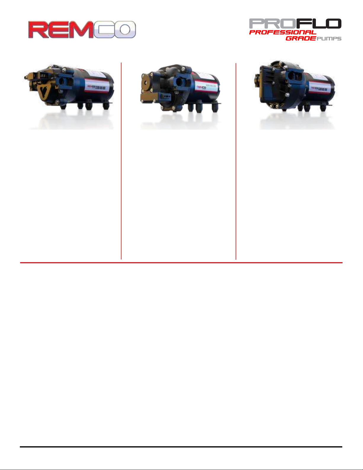
PUMP INFORMATION:
Type - 3 chamber diaphragm pump, self priming,
capable of being run dry
Pressure Control - Demand
Liquid Temperature - 140°F (60°C) Max.
Priming Capabilities - 10 feet (3 m)
Max Pressure - 100 PSI (6.9 bar)
Inlet/Outlet Ports - 3/4" Quick Attach
Weight - 5 lbs (2.3 kg)
MOTOR INFORMATION
Leads - 14 AWG, 7˝ long with 2-Pin
Temperature Limits - Motor is not equipped
with thermal protection. For user safety, optimal
performance, and maximum motor life, the motor
surface temperature should not exceed 180°F (82°C)
PUMP INFORMATION:
Type - 3 chamber diaphragm pump, self priming,
capable of being run dry
Pressure Control - Demand
Liquid Temperature - 140°F (60°C) Max.
Priming Capabilities - 8 feet (2.4 m)
Max Pressure - 200 PSI (14 bar)
Inlet/Outlet Ports - 3/4” Quick Attach
Weight - 6 lbs (2.7 kg)
MOTOR INFORMATION
Leads - 14 AWG, 7˝ long with 2-Pin
Temperature Limits - Motor is not equipped
with thermal protection. For user safety, optimal
performance, and maximum motor life, the motor
surface temperature should not exceed 180°F (82°C)
PUMP INFORMATION:
Type - 5 chamber diaphragm pump, self priming,
capable of being run dry
Pressure Control - Demand
Liquid Temperature - 140°F (60°C) Max.
Priming Capabilities - 14 feet (4 m)
Max Pressure Capabilities - 150 PSI (10 bar)
Inlet/Outlet Ports - 3/4” Quick Attach
Weight - 8 lbs (3.62 kg)
MOTOR INFORMATION
Leads - 14 AWG, 7˝ long with 2-Pin
Temperature Limits - Motor is not equipped
with thermal protection. For user safety, optimal
performance, and maximum motor life, the motor
surface temperature should not exceed 180°F (82°C)
12 Volt DC Motor-Driven Diaphragm Pumps
3300 Series: 2.2 GPM 3200 Series: 3.2-4.0 GPM 5500 Series: 4.0-5.3GPM
Remco Industries - 4605 County Rd 82 SE - Alexandria, MN - 763-253-4740 - www.remcoindustries.com
This manual suits for next models
3
Other Greenleaf Paint Sprayer manuals

Greenleaf
Greenleaf PSE Workhorse ATV 2527 Parts list manual

Greenleaf
Greenleaf Workhorse PSE ATV 1502 Parts list manual

Greenleaf
Greenleaf WORKHORSE SPRAYERS UTL Series Parts list manual

Greenleaf
Greenleaf Workhorse Sprayers 3PT Series Parts list manual

Greenleaf
Greenleaf Workhorse LG15STS Parts list manual