INSTRUCTION MANUAL
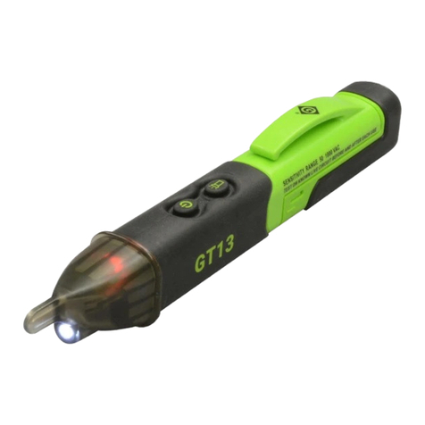
TR13 Voltage Detector
52087542 REV2 © 2019 Greenlee Tools, Inc. 10/19
Description
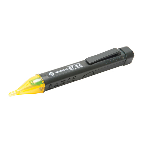
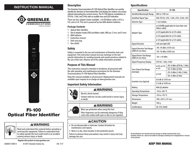
The Greenlee TR13 Voltage Detector is intended to check for the
presence of AC voltage, signaling the user with an intermittent
tone and flashing LED. The TR13 has a Self Test feature that
continuously tests the integrity of the entire unit including the
antenna. The TR13 also features low battery indication, an auto
power off feature and a flashlight.
This tool is protected by U.S. Patent No. 7,733,078, U.S. Patent
No. 9,146,262 and Canadian Patent No. 2,607,922. Other
patents pending.
Safety
Safety is essential in the use and maintenance of Greenlee tools
and equipment. This instruction manual and any markings on the
tool provide information for avoiding hazards and unsafe practices
related to the use of this tool. Observe all of the safety information
provided.
Purpose of This Manual
This instruction manual is intended to familiarize all personnel
with the safe operation and maintenance procedures for the
Greenlee TR13 Voltage Detector.
Keep this manual available to all personnel. Replacement manuals
are available upon request at no charge at www.greenlee.com.
Do not discard this product or throw away!
For recycling information, go to www.greenlee.com.
All specifications are nominal and may change as design improvements occur.
Greenlee Tools, Inc. shall not be liable for damages resulting from misapplication
or misuse of its products.
® Registered: The color green for electrical test instruments is a registered
trademark of Greenlee Tools, Inc.
ROMEX is a registered trademark of Southwire Company.
Symbols on the Unit
Warning—Read the instruction manual
Double insulation
Antenna tip
HHot side tip
NNeutral side tip
Important Safety Information
Read and understand this material before
operating or servicing this equipment. Failure
to understand how to safely operate this tool
could result in an accident causing serious
injury or death.
Electric shock hazard:
Wear appropriate personal protective
equipment, including eye protection and other
PPE as required by your employer.
Contact with live circuits could result in severe
injury or death.
Electric shock hazard:
•Do not assume that no voltage indication means that the
circuit is de-energized.
•Follow the 3-point safety method as described in the
“Operation” section (steps 3, 4, and 5).
• Do not use the unit if it is wet or damaged.
• Do not apply more than the rated voltage between the tip
and earth ground.
• Do not operate with the case open.
• This tester will not detect voltage through metal conduit, on
armored or shielded cable, on sheathed nonmetallic cable
that is saturated with water, or at a distance such as through
walls.
• Using this unit near equipment that generates
electromagnetic interference can result in unstable or
inaccurate readings.
• Grip unit with hand toward the center of the main body
during normal operation; otherwise, the sensitivity of the
tester can be affected leading to inaccurate readings.
Failure to observe these warnings could result in severe injury
or death.
Electric shock hazard:
• Do not attempt to repair this unit. It contains no
user-serviceable parts.
• Do not attempt to repair or reshape the antenna if it becomes
bent or deformed. The unit must be replaced.
• Do not expose the unit to extremes in temperature or high
humidity. Refer to “Specifications.”
Failure to observe these precautions may result in injury and
can damage the unit.
Lifetime Limited Warranty
Greenlee Tools, Inc. warrants to the original purchaser of these goods for use that
these products will be free from defects in workmanship and material for their
useful life, excepting normal wear and abuse.This warranty is subject to the same
terms and conditions contained in Greenlee Tools, Inc.’s standard one-year limited
warranty.
For all Test Instrument repairs, contact Customer Service at
800-435-0786 and request a Return Authorization.
For items not covered under warranty (such as items dropped, abused, etc.), a
repair cost quote is available upon request.
Note: Prior to returning any test instrument, please check replaceable batteries or
make sure the battery is at full charge.
99 Washington Street
Melrose, MA 02176
Phone 781-665-1400
Toll Free 1-800-517-8431
Visit us at www.TestEquipmentDepot.com
