Greentek DOUBLE-QUICK User manual

OPERATOR’S MANUAL

INTRODUCTION
Congratulations on purchasing a first-class British designed and manufactured Turf Maintenance System!
To ensure operator safety and obtain maximum service life from this machine it is essential that ALL operators
read and thoroughly understand this manual. If at any time there is anything you are unsure about, the
manufacturers will be pleased to help.
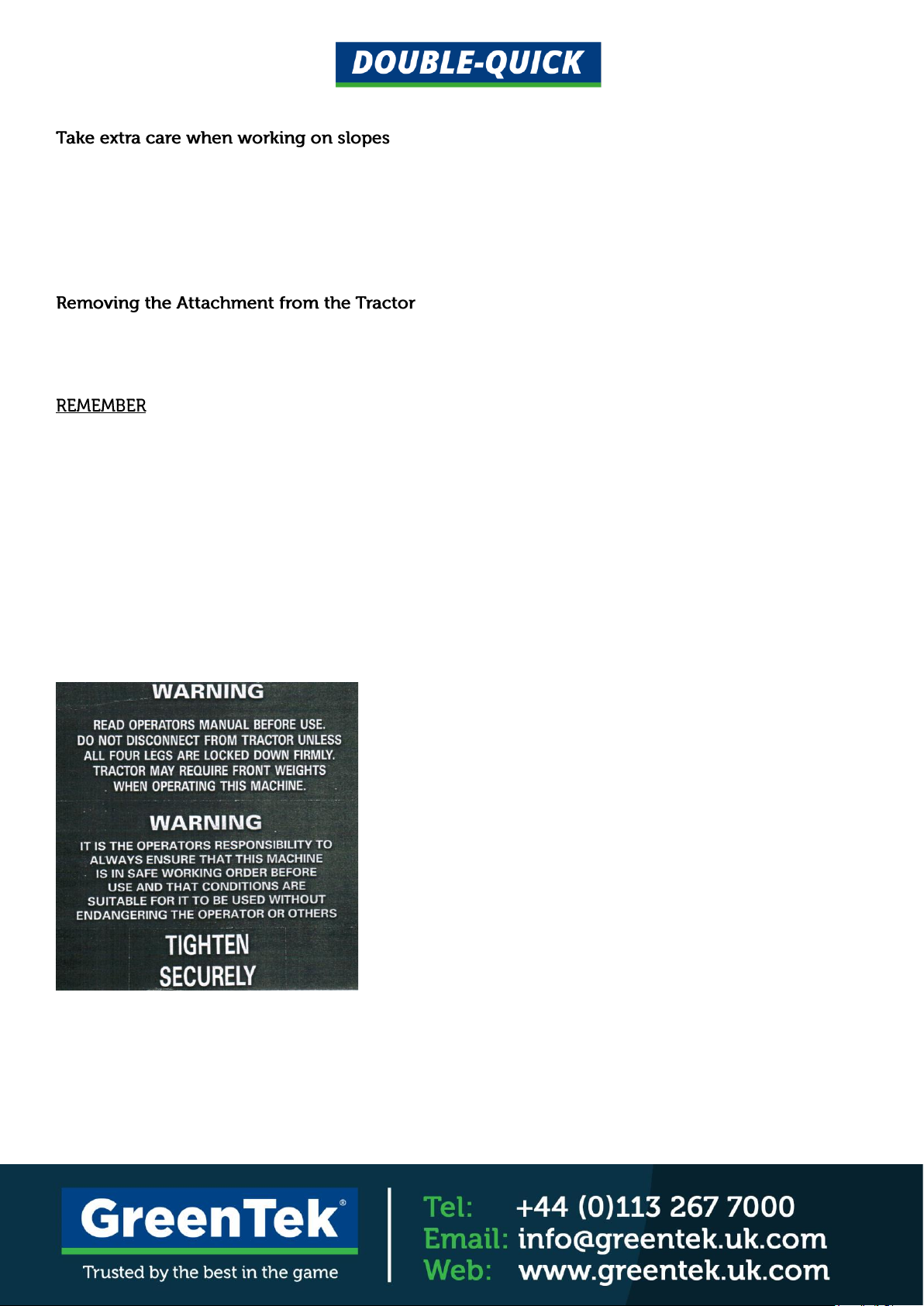
SAFETY WARNINGS
This turf maintenance system is designed to be operated by a tractor of not less than 35HP with a hydraulic
lifting capacity of at least 1 tonne. Front weights may be necessary when operating this machine.
All operators must also read and follow all instructions in the operators handbook supplied with the tractor.
Check that the brakes are applied, drives are in neutral, guards are in position and intact and bystanders
are clear of the machine. Do not run the engine in a building without adequate ventilation.
Before moving the machine, check to ensure that all the parts are in good working order, paying particular
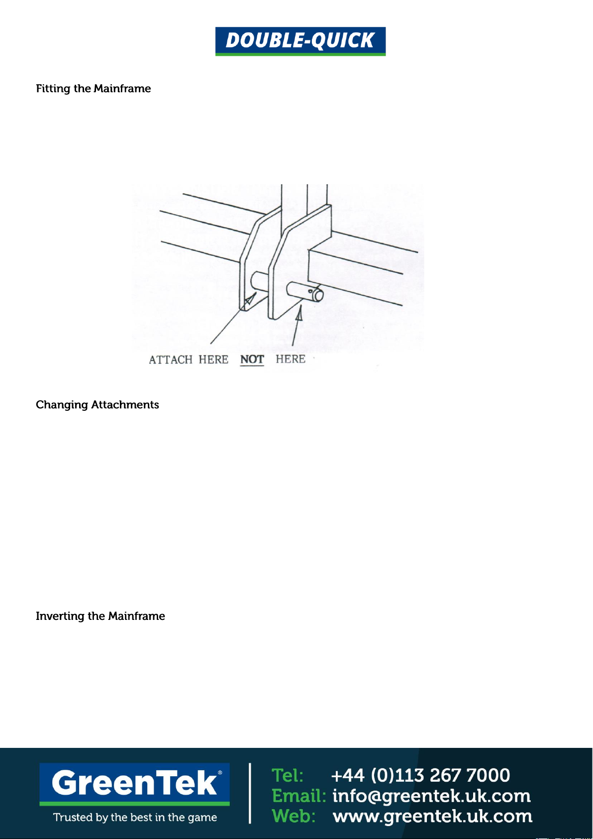
attention to tyres, steering, brakes and lights. Double check that the attachment is fitted securely to the
tractors’ 3 point linkage.
Always observe the Highway Code both on and off the roads. Keep alert and aware at all times. Remember
that some people are deaf or blind; that children and animals can be unpredictable. Keep travelling speeds
low enough for an emergency stop to be effective and safe at all times.
Take special care when reversing and ensure the area behind is clear of obstructions. Remove or avoid
obstructions in the working area.
Park the tractor on level ground. Before leaving the driving seat, stop the engine and make sure all moving
parts are stationary. Apply brakes and disengage all drives. Remove the ignition key.

Local undulations and sinkage will change the general slope. Avoid ground conditions which will cause the
tractor to slide or roll over. Apply brakes before disengaging tractor gears. Keep the tractor completely under
control when disengaging the traction clutch. Remember that the extra weight of the attachment will affect the
balance and stability of your tractor.
Lock down all four drop legs BEFORE uncoupling the attachment from the 3 point linkage.
IT IS THE OPERATOR’S RESPONSIBILITY TO ALWAYS ENSURE THAT THIS MACHINE IS IN SAFE
WORKING ORDER BEFORE USE AND THAT CONDITIONS ARE SUITABLE FOR IT TO BE USED
WITHOUT ENDANGERING THE OPERATOR OR OTHERS.
WARNING DECALS
The following decals are affixed to your Double-Quick which must be obeyed at all times. Replacement decals
are available free of charge from the manufacturers.

LOADING AND UNLOADING THE MACHINE
The machine can be loaded on and off a lorry using a fork lift truck and suitable slings with a SWL of over
1 tonne. Remove the top guard and fit two slings, one for each fork as shown in Figure 1.
USING THE DOUBLE-QUICK SYSTEM
The system comprises of a mainframe and a range of interchangeable attachments for rolling and aerating.
The slitting attachments are designed to be used working in straight lines. Lower the machine slowly into
the ground whilst moving forward. Do not reverse with machine touching the ground otherwise damage may
occur. Lift the machine on the 3 point linkage at the end of each pass BEFORE turning and lining up for the next
pass.
On no account should you try to make a turn with the slitters lowered into operation as this could result
in damage to the machine. Very slight turns may be make when using the roller attachment but sharp turns
will result in scuffing the turf.
Always work in the same direction throughout a season when slitting. Working at right angles to previous
passes can result in severe lifting of the turf.

Couple the mainframe to the tractor 3 point linkage by means of the dual category (1 & 2) pins provided.
NOTE: It is essential that the tractor lifting arms are located between the plates of the lower linkage point
of the main frame. Do not hook the lifting arms over the pins on the outside of these plates.
To remove an attachment from the mainframe, it should be coupled up to the tractor with the attachment to be
removed in the lower position. This may require inversion of the mainframe (see ‘Inverting the Mainframe’).
Raise and lock, by means of the locking bolts, all four drop legs. With the attachment resting on the ground
undo the four bolts holding the two bearing housings to the mainframe. Lift the mainframe off the attachment
by means of the tractor 3 point linkage.
Drive away the tractor and reposition if it so that the mainframe is now directly above the next attachment to
be fitted. Lower the mainframe and attach the two bearing housings using the four bolts and nuts previously
removed.
If the bolt holes in the bearing housing do not quite line up with those in the frame, slacken the two Allen
screws in the bearing, reposition it as required, and retighten the screws.
In order to use an attachment presently fitting in the upper position, the mainframe must be inverted. To do this,
park the tractor on firm, level turf (NOT concrete or Tarmac) with adequate space to manoeuvre and lower the 3
point linkage. Lock the four drop legs half way down and remove the top guard.

Uncouple the 3 point linkage and drive the tractor around to the other side of the mainframe, REVERSING
up to within 2 metres of it. Attach the tow cable provided to the CENTRE mounting point on the LOWER rail
of the mainframe (see Figure 3), pass it over the top of the mainframe and attach it to a suitable towing point
on the rear of the tractor.
After making sure that there is nobody anywhere near the tractor or mainframe, drive slowly forward to roll the
mainframe over through 180°. Remove the tow cable, recouple the tractor to the mainframe, refit the top guard
and raise and lock up the droplegs.
WARNING:
THE TOW CABLE PROVIDED MUST NOT BE USED FOR ANY OTHER PURPOSE THAN THAT DESCRIBED
ABOVE. NEVER USE IT FOR LIFTING MACHINERY OR TOWING VEHICLES ETC.

3. Remove the top guard.
4. Uncouple the 3 point linkage and
allow the frame to tilt over slightly onto
the 2 rear stand legs.
Double-Quick Rollover Procedure
1. Lock all 4 stand legs in the
central position.
2. If a rear attachment is fitted,
remove it by means of the 4
clevis pins and put it to one side.
5. Drive the tractor round to the
other side of the Double-Quick
and reverse up to it squarely and
centrally.
6. Attach the tow cable provided
to the top link position on the
tractor.

7. Pass the tow cable over the
top attachment and secure with
the top link pin to the lower
centre mounting position.
12. Raise the stand legs and lock
up into the working position.
10. Reverse the tractor and re-attach
the 3 point linkage.
8. Ensure all bystanders keep back
and drive the tractor very slowly
forward causing the Double-Quick
to rotate.
9. As soon as the Double-Quick
starts to continue rolling under its
own momentum STOP the
tractor and allow it to come to
rest on its 4 legs by itself.
11. Replace the top guard.

To uncouple the mainframe from the tractor, first lift the 3 point linkage, then fully lower and securely lock
down all four drop legs. Then lower the mainframe and uncouple from the tractor.
NEVER UNCOUPLE THE MAINFRAME FROM THE TRACTOR UNLESS ALL FOUR DROP LEGS ARE
SECURELY LOCKED DOWN.
MAINTENANCE
Inspect the whole machine paying particular attention to tightness of all nuts and bolts and condition of tines
and tow cable. Check for cracks or breakages, particularly around the mounting points on the mainframe
and the condition of the linkage connecting pins.
Grease bearings using a lithium grease.
ATTACHMENTS
A filler plug is fitted to one end of the roller to allow it to be ballasted to increase its weight for heavy rolling.
In addition, the roller may be fitted in the upper position to give increased penetration to a slitting attachment
beneath. Use only the minimum ballast sufficient to obtain the depth of penetration required. Drain water if
there is any possibility of freezing.
A roller scraper is available if problems of mud building up on the roller are encountered.
This is fitted to the mainframe with the tines angled forward.
The tines on this attachment are symmetrical in design. It can therefore be fitted to the mainframe either way
round.

This is available with either ‘open’ or ‘closed’ spoon tines and is used for hollow coring.
The rear roller may be used in conjunction with an aerating attachment to firm down any divots. A roller
scraper is available if problems of mud building up on the roller are encountered. In addition a scarifying
rake and/or Brush may be fitted on to the rear roller carrier allowing all four operations to be carried out
simultaneously. The whole assembly attaches to the main frame by means of four clevis pins with R clips
and must be detached prior to rolling over the main frame.
DO NOT REVERSE WITH RAKES ON THE GROUND OTHERWISE DAMAGE WILL OCCUR.
If only one attachment is purchased with the mainframe, a weight tray is supplied instead of a top guard.
This can be ballasted with bags of sand to give increased penetration to the attachment in operation if
necessary.
COMPONENT
6FT
8FT
Mainframe
200kg
290kg
Top Guard
20kg
30kg
Weight Tray
57kg
65kg
Deep Slitter
122kg
160kg
Fine Turf Slitter
129kg
170kg
Solid Tiner
200kg
320kg
Hollow Corer
120kg
180kg
Ballast Roller
180kg
200kg
Rear Roller & Carrier
91kg
115kg
Rear Rake
17kg
20kg
Core Recycler
200kg
------

PARTS LISTING FOR 6’ DOUBLE-QUICK

PARTS DIAGRAM FOR DOUBLE-QUICK


PARTS LISTING FOR 8’ DOUBLE-QUICK


We guarantee that should any defect in materials or workmanship occur within 24 months of purchase,
we will repair or, at our option, replace the defective parts free of charge provided that the fault is reported
to us immediately it becomes apparent.
Damage caused by normal wear, misuse or in transit is not covered by this guarantee.
CONTACT US
For further information, support or advice please contact:
+44 (0) 113 267 7000
Table of contents
Other Greentek Lawn And Garden Equipment manuals