GREMSY T3 User manual


REVISION HISTORY
LEGEND
WARNING
NOTE
DATEREVISION DESCRIPTION
Notes are used to highlight special operating conditions or steps of a
procedure.
Warnings are used to highlight procedures which, if not strictly
observed, may result in personal injury or loss of life.
Tips.
TIPS
1.0 Feb 18th 2020 User Manual

Revision History 2
Legend 2
GETTING STARTED 6
Introduction 7
Features 8
HDMI Hyper Quick Release
Plug & Play
New I/O Design
Heated & Temperature Controlled IMU
High Performance Gimbal Controller
Clean Design - Internal Wiring
Built for Aerial Work
Specications 11
Gremsy T3 Mechanical Components 12
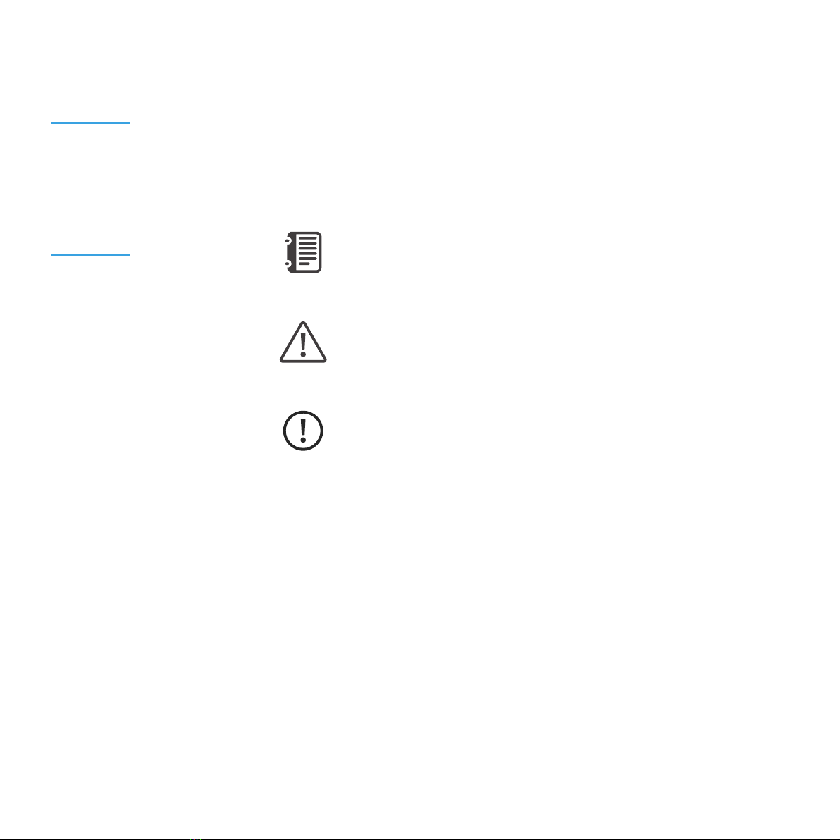
Gremsy T3 I/O Connectors 13
Hyper Quick Release Connectors & Pinouts
Camera Tray Connector & Pinout
What’s In The Box 17
hdmi Hyper Quick Release 18
Mounting Hyper Quick Release
Connect
Disconnect
Powering Up The Gremsy T3 20
Step 1
Step 2
Step 3
Status LED Indicator 21
CONTENTS

Operation Modes 22
Gremsy T3 Has 2 Operation Modes
Gremsy T3 Supports
Working Operation
Swithching Between Modes
Installing Software / App 26
Using USB/BLUETOOTH Connection 27
Using USB Connection
Using BLUETOOTH Connection
BALANCING 29
Mounting The Camera 30
Mounting The Hot Shoe Adapter 31
Tilt Axis Front-Back Balance 32
Tilt Axis Vertical Balance 33
Roll Axis Balance 34
Pan Axis Balance 35
SOFTWARE - TUNING 36
Stiffness Tuning 37
General Method
Step 01 - Tilt Stiffness
Step 02 - Roll Stiffness
Step 03 - Pan Stiffness
Auto tuning 39
Filter 40
Gyro Filter
Output Filter
Default Values

Expert / advanced settings 41
Hold Strength
Gain
Default Settings
Follow Mode Settings 43
Speed
Smooth
Window
Tilt Lock
Airborne
Rotation Limit 45
Up Limit
Down Limit
Roll Offset
IMU Sensor 46
Gyro Calibration
Accelerometer Calibration
REMOTE CONTROL 49
SBUS/PPM Settings 50
Receiver Connection
Channel Setting
JR/SPEKTRUM Settings 52
JR / Spektrum Satellite Receiver Connection
Channel Settings
UPGRADING FIRMWARE 53
How To Upgrade 54
TROUBLESHOOTING 55

GETTING STARTED

7
GETTING STARTED
The new T3 features HDMI Quick Release as well as new I/O design and the
ability to start up in 2 seconds. Moreover thanks to the increase in regulated
voltage motor power is also increased up to 20%
INTRODUCTION

8
GETTING STARTED
FEATURES
HDMI HYPER QUICK RELEASE
PLUG & PLAY
NEW I/O DESIGN
New mechanical and electrical integration
quick release features oating connectors
that allow to transmit high speed HDMI
video signal while still maintain reliability
after many mating cycles.
Say goodbye to complex setups and time
consuming process. The T3 provides an
easy one step plug and play installation that
takes only 5 seconds to complete.
Intuitive hardware interface including a
variety of ports has relocated on QR to
quickly interface with multiple devices such
as 3rd party ight controller, remote control,
auxiliary I/O and power your ideal system of
cameras/accessories.

9
GETTING STARTED
HEATED & TEMPERATURE
CONTROLLED IMU
Heated and temperature controlled IMU
sensor with advanced 6-point calibration
allows reliable performance even in extreme
weather. Temperature is maintained within
0.2 degrees Celsius accuracy.
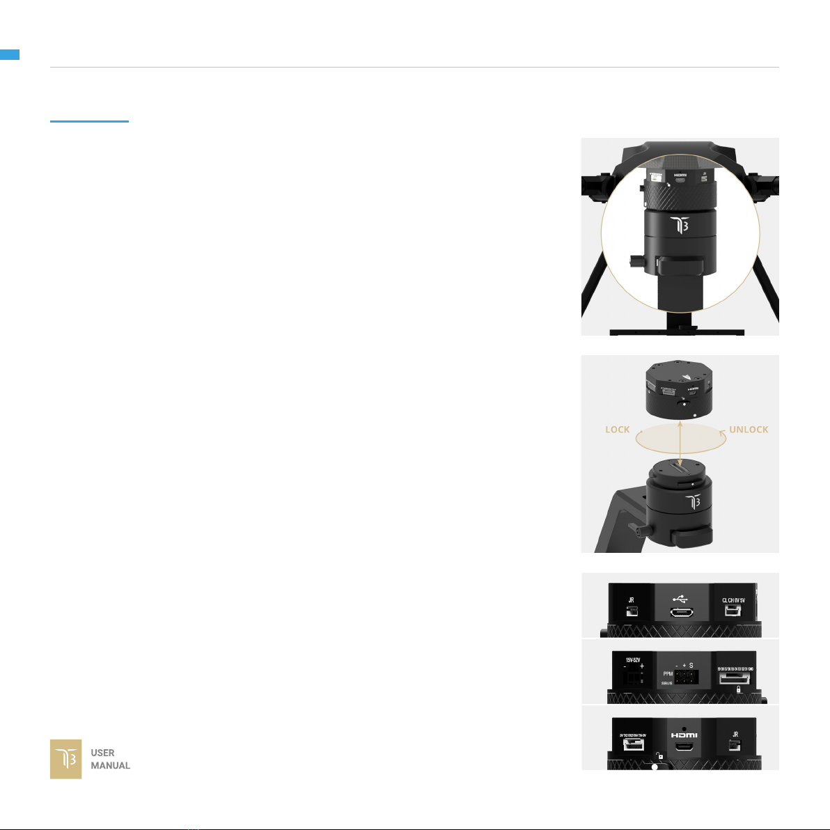
HIGH PERFORMANCE
GIMBAL CONTROLLER
gMotion Controller, designed and made by
Gremsy based on a 32 bit high performance
ARM microprocessor providing fast
response and accurate calculation. Sensor
data and motors correction are updated as
fast as 2000 times per second to enable
incredibly smooth footage.
CLEAN DESIGN - INTERNAL
WIRING
No exterior wires, more solid. This clean
design helps the T3 overcome wind
resistance with ease to bring out the best
video quality while staying agile.

10
GETTING STARTED
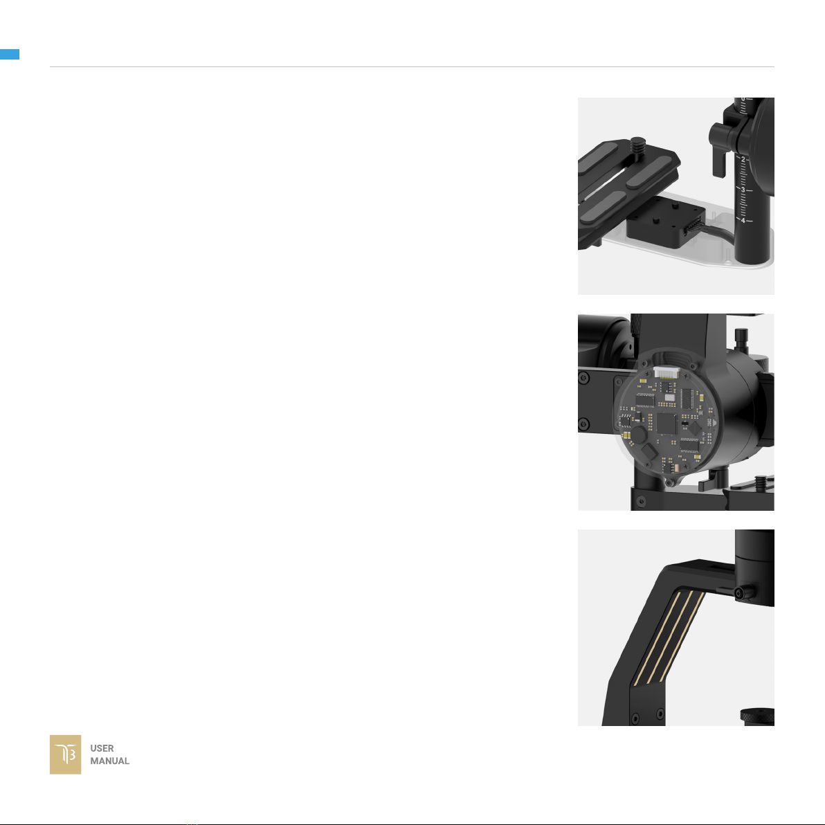
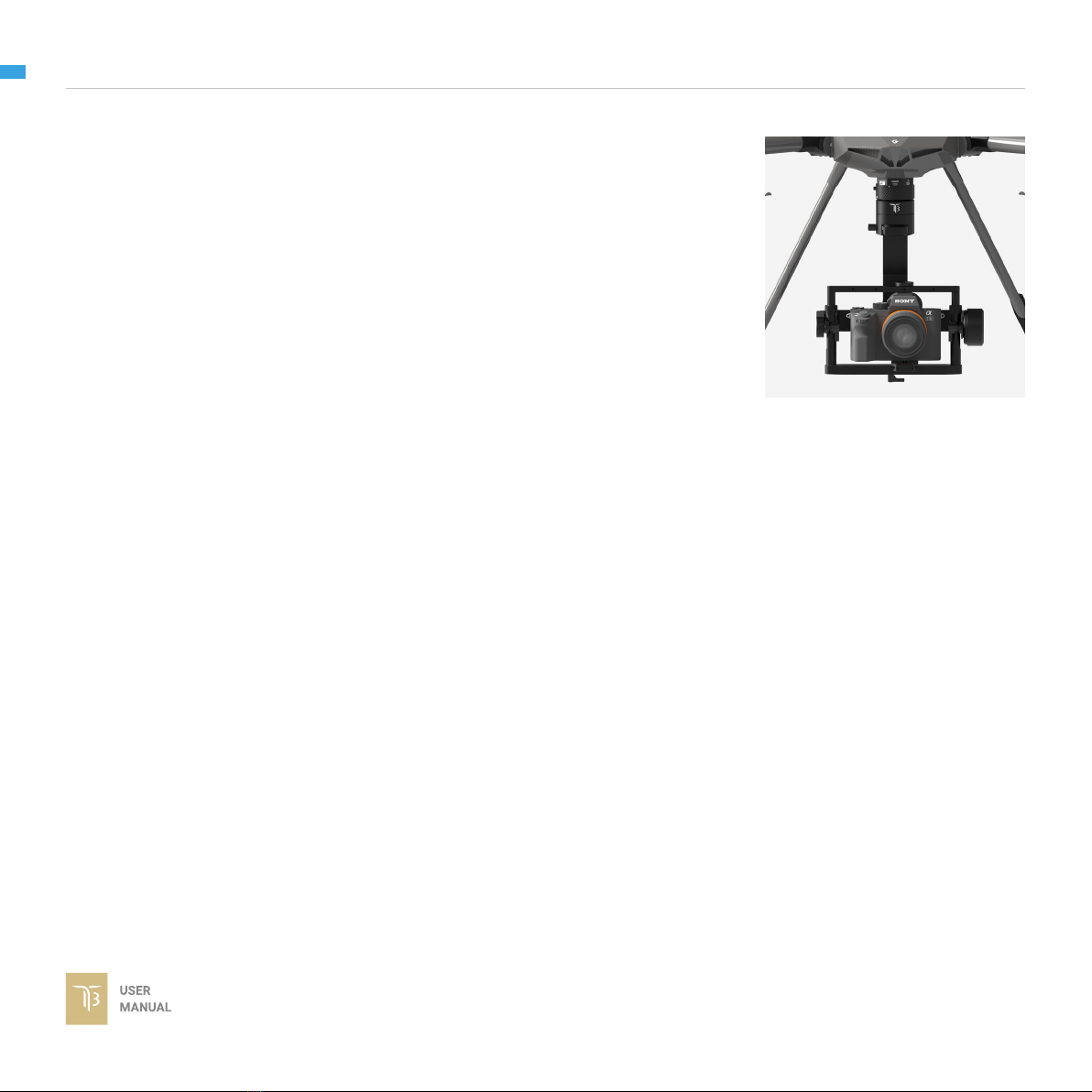
BUILT FOR AERIAL WORK The T3 has a lot of nice features that enable
users to apply it not only for aerial inspection
and mapping but also for high end aerial
cinematography.

11
GETTING STARTED
SPECIFICATIONS Product Name
System Type
Weight
Camera Cage (Standard) (W X L X H)
Construction
Input Voltage
Working Current
Connection
Payload
OS Platform Supported
Single Operator
Dual Operator
Pan Range
Tilt Range
Roll Range
Gremsy T3
3-Axis Digital Gyro-Stabilized
2.65 lbs / 1200 g
152mm x 100mm x 120mm
All Aluminum
15 – 52V
Static Current 300mA @14.5V
Dynamic Current 600mA @14.5V
Locked Motor Current Max 4A @14.5V
USB, CAN, UART, BLUETOOTH
3.75lbs/1700g
Windows / Mac / iOS / Android
Follow Mode / LB2
SBUS / Spektrum / PPM / LB2
+/- 345 degree
+/- 150 degree
+80/- 264 degree

12
GETTING STARTED
GREMSY T3
MECHANICAL
COMPONENTS
01. HDMI Hyper quick release
02. Pan motor
03. Pan adjustment
04. Roll motor
05. Gimbal controller
06. Roll adjustment
01
02
03
04
05
06
07
08
09
11
10
12
07. Tilt motor
08. Tilt top bar
09. Camera plate
10. Tilt front- back adjustment
11. Tilt vertical adjustment
12. Top camera screw

13
GETTING STARTED
GREMSY T3 I/O
CONNECTORS
HYPER QUICK RELEASE
CONNECTORS & PINOUTS
POWER: to get power directly from
external batteries of the drone or other
power supply. Voltage input range from 15V
to 52V and is down converted to a stable
14.5V by the internal circuit to provide power
to gimbal and accessories.
Connector type: Molex Microt 3.0 2 pin
CAN: to interface with CAN bus on DJI
Flight controller or another module that uses
CAN bus.
Connector type: JST SM04B-ZESS-TB
COM2/COM4: to interface with Pixhawk
or Pixhawk 2 via Mavlink protocol or other
modules that use serial protocol (UART).
Connector type: JST SM06B-ZESS-TB

14
GETTING STARTED
AUX: There are S1, S2, S3,...,S8,S9
optional signal (0.25A max) for users to
connect to other devices such as AV signal
or camera trigger...This port is internally
connected to AUX port on the camera tray.
Connector type: JST SM10B-ZESS-TB
USB: to interface with computer or
upgrading rmware
Connector type: Micro USB TYPE B
SBUS/PPM: To interface with SBUS/PPM
receiver.

15
GETTING STARTED
HDMI: HDMI video output from the
camera.
Connector type: Micro HDMI
JR: to interface with JR/SPEKTRUM
satellite receiver.
Connector type: JST S3B-ZR

16
GETTING STARTED
CAMERA TRAY
CONNECTOR & PINOUT
AUX: There are S1, S2, S3,...,S8,S9
optional signal (0.25A max) for users to
connect to other devices such as AV signal
or camera trigger...This port is internally
connected to AUX port on the Hyper Quick
Release.
Connector type: JST SM10B-ZESS-TB
PWT OUT: 14.5V 2A output for camera
and accessories.
Connector type: JST S2B-XH-A(LF)
HDMI: HDMI video input from the camera.
Connector type: Micro HDMI

17
GETTING STARTED
WHAT’S IN THE BOX
A. Micro USB Cable
B. Power Supply Cable
C. Canlink Cable For Pixhawk (COM2/COM4)
D. Canlink Cable For DJI A3/N3
E. Sbus Cable
F. Auxiliary Cable
G. PWT Accessories Cable
H. Allen Key Set
x1
x1
x1
x1
x1
x2
x1
x1
01. GREMSY T3 GIMBAL 02. HDMI HYPER QUICK RELEASE
03. SLIDE CAMERA & CAMERA SCREW 04. HOTSHOE EXTENSION
05. GREMSY T3 CABLES & TOOLS

18
GETTING STARTED
HDMI HYPER
QUICK RELEASE
MOUNTING HYPER QUICK
RELEASE
CONNECT
Using 32mm square M3 pattern to mount
the top part onto the frame or damping
isolator.
STEP 1: The marks on the top part and bottom part must be aligned. The
button on the ring should be aligned with the unlocked icon as shown in the rst
picture.
STEP 2: Keep everything aligned and attach the bottom part to the top part.
STEP 3: Rotate the ring clockwise until hearing a snap, the button should be
automatically popped out and aligned with a locked icon.

19
GETTING STARTED
DISCONNECT
STEP 1: Press and hold the button.
STEP 2: Rotate the ring counterclockwise.
STEP 3: When the button aligns the unlock icon, the T3 can be detached from
the top part of Hyper Quick Release.

20
GETTING STARTED
POWERING UP
THE GREMSY T3
Always start the gimbal with a balanced camera set up otherwise after
initialization the controller will return an error followed by a red color
indicator.
If the status LED is solid red, something is wrong with the gimbal and
motors can not start. Connect to the software/apps to check details of
the error message.
Make sure the Hyper Quick Release is mounted to the drone and its power port is
already connected to the power supply correctly. Next, let’s mount the gimbal to
the Hyper Quick Release, it will be automatically powered up.
Wait about 2 seconds, do not touch the gimbal or camera.
If the status LED is blinking green, the gimbal is ready for use. By default, the
gimbal is in Follow mode if the motors are turned ON by the Function Button.
Read “LED STATUS INDICATOR” in next section for more information.
NOTE
NOTE
STEP 1
STEP 2
STEP 3
After connecting to the power supply, the gimbal will perform a series of
alignments, self tests, which last about 2 seconds and will determine the status
of the gimbal, indicated by the Status LED color. During this time, don’t touch the
gimbal or camera.
Other manuals for T3
1
Table of contents
Other GREMSY Camera Accessories manuals