Greystone Energy Systems GT-ARES Series User manual

IN-GE-GTARESXXX-01-02 02/19 Page 1
Copyright © Greystone Energy Systems, Inc. All Rights Reserved Phone: +1 506 853 3057 Web: www.greystoneenergy.com
INTRODUCTION
The analog resistance module is an interface that accepts an
analog signal input (voltage or current) and uses that signal to
proportionally control a variable resistance output. The device
output simulates a 3 wire slide wire or rotary potentiometer. The
resistive output is electrically isolated from the input control
signal.
The input signal type is DIP switch selectable to one of several
factory calibrated standard ranges and the output has both ends
of the potentiometer and the wiper available on the terminal
connectors. The output resistance simulates a potentiometer
and does not wrap around at the end points.
The resistance module includes a regulated power output that can be used to power a current-loop
transducer and also features a failsafe input that will connect to the output terminals in case of power
loss or for manual output control. There is also an LED power indicator and a manual override jumper for
failsafe operation.
The product comes with standard snap-track for easy mounting or is available with various resistance
values.The potentiometer may be ordered with no oset value such as 0-135 Ω, or may be congured with
an oset resistance such as 20-30K Ω.
BEFORE INSTALLATION
Read these instructions carefully before installing and commissioning the signal interface. Failure to follow
these instructions may result in product damage. Do not use in an explosive or hazardous environment,
with combustible or ammable gases, as a safety or emergency stop device or in any other application
where failure of the product could result in personal injury. Take electrostatic discharge precautions
during installation and do not exceed the device ratings.
MOUNTING
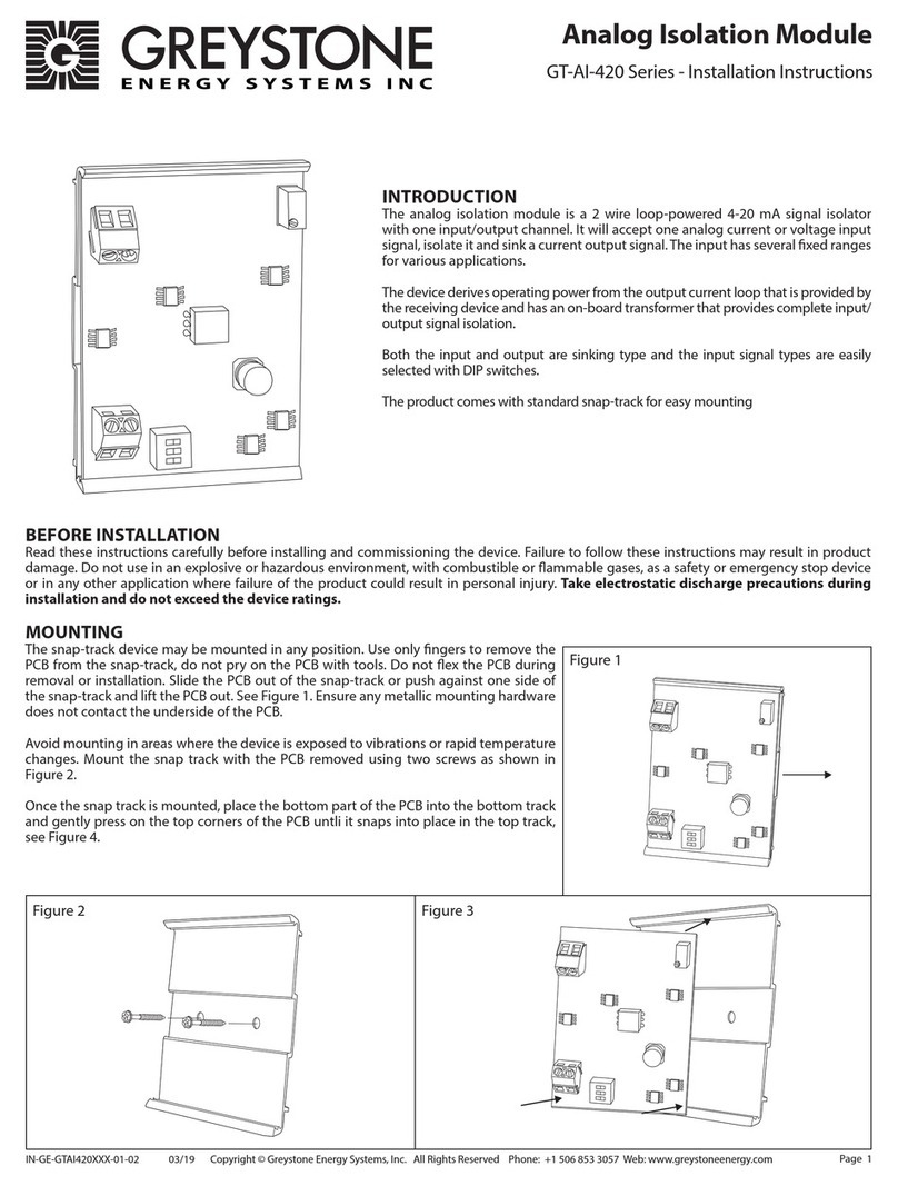
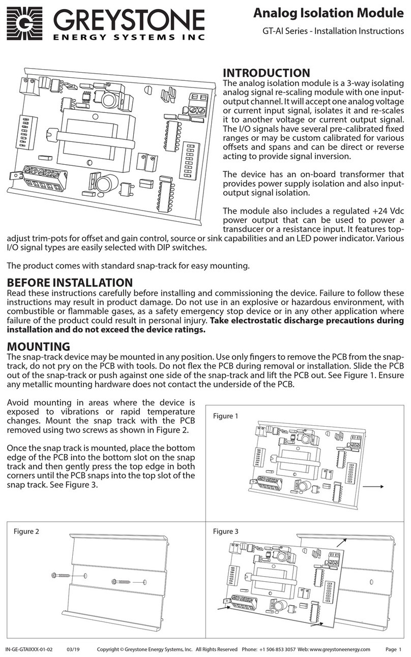
The snap-track device may be mounted in any position. Use only ngers to remove the PCB from the snap-
track, do not pry on the PCB with tools. Do not ex the PCB during removal or installation. Slide the PCB
out of the snap-track or push against one side of the snap-track and lift the PCB out. See Figure 1. Ensure
any metallic mounting hardware does not contact the underside of the PCB.
Avoid mounting in areas where the signal interface
is exposed to vibrations or rapid temperature
changes. Mount the snap track with the PCB
removed using two screws as shown in Figure 2.
Once the snap track is mounted, if there is no room
around the device to slide the PCB back into the
snap track, place the top part of the PCB into the
top track and pull the bottom edge of the snap
track down to place the bottom edge of the PCB
into the snap track, see Figure 3.
Analog Resistance Module
GT-ARES Series - Installation Instructions
Figure 1
Figure 3Figure 2

IN-GE-GTARESXXX-01-02 02/19 Page 2
Copyright © Greystone Energy Systems, Inc. All Rights Reserved Phone: +1 506 853 3057 Web: www.greystoneenergy.com
WIRING
• Deactivate the 24 Vac/dc power supply until all connections are made to the device to prevent
electrical shock or equipment damage. Follow proper electrostatic discharge handling procedures
when installing the device or equipment damage may occur.
• Use 22 AWG shielded wiring for all connections and do not locate the signal interface wires in the same
conduit with wiring used to supply inductive loads such as motors. Make all connections in accordance
with national and local codes.
WIRING POWER INPUT
• Connect the plus DC or the AC voltage hot side to the PWR terminal.The supply common is connected to
the COM terminal. The device is reverse voltage protected and will not operate if connected backward.
It has a half-wave power supply so the supply common is the same as the input signal common.
• Several devices may be connected to one power supply and the input signals all share the same
common.
• Ensure the supplied power is within the device ratings. Power supply voltages outside the ratings may
cause over-heating, device damage or unreliable operation.
WIRING INPUT SIGNAL
• The analog input signal is connected to the IN terminal. The input signal is referenced ti the COM
terminal.
• Ensure the INPUT SELECT switches are set for the correct signal type, either voltage or current. The
input signal will typically come from a DDC or BAS analog output.
WIRING POWER OUTPUT
• The 20V terminal is a regulated power supply output which provides a 20 Vdc power supply at 30 mA
maximum that can be used to operate an external sensor.
WIRING RESISTANCE OUTPUT
• The signal interface output stimulates a potentiometer.
• Terminal R is the wiper, terminal W is the low end (minimum) of the pot and terminal.
• Terminal B is the high end (maximum) of the pot.
Study the wiring diagrams for proper connections with various input/output signal types and with both
sinking or sourcing applications.
Figure 6
Figure 4 Figure 5
POWER
OFF ON
S1
S2
S3
S4
INPUT SELECTION
MAN AUTO
PWR COM 20V IN W=MIN B=MAX W R B W R B
FAILSAFE OUTPUT
+
-
PWR
COM
20V
IN
24 Vac/dc Power Supply
Loop Powered Sensor
+
-
+
-
PWR
COM
20V
IN
24 Vac/dc Power Supply
0-10 Vdc From BAS
+
-
Using the 20V output to power a loop-powered sensor
Congure the input DIP switches for 4-20 mA
Connecting a 0-10 Vdc signal from a controller
Congure the input DIP switches for 0-10 Vdc
W (minimum)
R (wiper) R (wiper)
B (maximum)
W
R
B
W
R
B
Direct Acting Reverse Acting
Congure a 2 wire resistance output for direct or reverse acting operation
W
R
B
W
R
B
Jumper W-R for Failsafe
to minimum value
Jumper B-R for Failsafe
to maximum value
Connect an external pot for manual control
Set the jumper to MAN for manual control
W
R
B

IN-GE-GTARESXXX-01-02 02/19 Page 3
Copyright © Greystone Energy Systems, Inc. All Rights Reserved Phone: +1 506 853 3057 Web: www.greystoneenergy.com
For example, two applications are shown below.
OPERATION INPUT AND OUTPUT SIGNALS
The input signal type is selected with the 4 position DIP switch labeled INPUT SELECT. The available
input signal types and DIP switch positions are shown in the chart below.
The ranges shown in the chart are all pre-calibrated such that 0-100% of the input signal will cause the
output resistance from W to R to change from the pot minimum to the maximum value.
Upon power up, the wiper will start at the W position but will immediately sample the input signal and
move to the resistance value proportional to the input signal and the selected input range.
For example, for a 0-5 Vdc input signal and a 0-135 Ω pot, the resistance between W (min) and R (wiper)
will be 0 Ω for 0 Vdc input and the resistance between B (max) and R (wiper) will be 135 Ω. As the
input signal increases from 0 to 5 Vdc, the resistance between W and R will increase and the resistance
between B and R will decrease until the input signal is 5 Vdc. At 5 Vdc the W-R resistance will be 135 Ω
and the B-R resistance will be 0 .
The resistance output has a minimum and maximum value and does not wrap around. In the above
example with 0-5 Vdc input signal, the W-R resistance will increase to 135 Ω and will stay at 135 Ω even in
6 Vdc is applied to the input.
Voltage input signals are referenced to the COM terminal and have an input impedance of >10 KΩ.
Current input signals are also referenced to COM and have an input impedance of 250 Ω. The current
input is a sinking type signal, the controller must source the 0-20 mA signal.
The signal interface features a micro-controller for highest accuracy and includes input ltering and
hysteresis to prevent relay chatter or hunting for the correct output resistance value. The output
resistance is controlled with a 256 bit resolution.
OPERATION FAILSAFE INPUT
The signal interface OUTPUT terminals are connected to the resistance values through a DPDT relay
that is used to control the failsafe function. During normal operation with power applied to the signal
interface, the pot resistance is connected to the OUTPUT terminals.
In the event of a power loss, the failsafe relay will disconnect the OUTPUT terminals from the pot value
and instead connect the OUTPUT terminals directly to the FAILSAFE terminals.
Input Type S1 S2 S3 S4
0-5 Vdc OFF OFF OFF ON
0-10 Vdc OFF ON OFF ON
0-15 Vdc OFF OFF ON ON
1-5 Vdc OFF OFF OFF OFF
2-10 Vdc OFF ON OFF OFF
3-15 Vdc OFF OFF ON OFF
0-20 mA ON OFF OFF ON
4-20 mA ON OFF OFF OFF
0-5 Vdc Input Type 4-20 mA Input Type
OFF ON OFF ON
S1
S2
S3
S4
S1
S2
S3
S4
INPUT SELECTION INPUT SELECTION

PRINTED IN CANADA
IN-GE-GTARESXXX-01-02 02/19 Page 4
Copyright © Greystone Energy Systems, Inc. All Rights Reserved Phone: +1 506 853 3057 Web: www.greystoneenergy.com
This is useful in several ways, for example, discreet resistor may be connected to the W (min) and R
(wiper) terminals of the FAILSAFE connector to set a minimum resistance value on power failure. If the
signal interface is controlling a damper actuator, then the resistance would set a minimum open position
on power failure.
To failsafe to the minimum signal interface resistance value, connect a wire jumper between the W and R
terminals of the FAILSAFE connector.
To failsafe the maximum signal interface resistance value, connect a wire jumper between the B and R
terminals of the FAILSAFE connector.
A manual potentiometer may also be connected to the FAILSAFE connector to allow manual control.
The PCB has a MAN / AUTO jumper that can be used to force the failsafe mode. For normal operation the
jumper is placed in the AUTO position. To test the system, place the jumper in the MAN position and the
OUTPUT terminals will immediately connect to the FAILSAFE terminals so an external pot can be used to
manually control the device connected to the signal interface output.
Return the jumper to the AUTO position for normal operation.
SPECIFICATIONS
POWER OUTPUT
Regulated Power Output............ 20 Vdc ± 10% (use to power an external sensor)
Power Output Drive...................... 30 mA maximum
INPUT SIGNAL
Voltage Range ................................ 0-5, 0-10, 0-15, 1-5, 2-10, or 3-15 Vdc (switch selectable)
Voltage Impedance ...................... >10 KΩ
Current Range................................. 0-20 or 4-20 mA (switch selectable)
Current Impedance....................... 250 Ω
OUTPUT SIGNAL
Signal Type....................................... Simulated potentiometer resistance (3 wire)
Resolution........................................ 256 steps (no wrap around)
Resistance Accuracy ..................... ±5%
Standard Values ............................. 0-135 Ω, 4.5 watts
0-270 Ω, 3.0 watts
0-500 Ω, 3.0 watts
0-1000 Ω, 1.0 watts
other ranges available
GENERAL
Power Supply.................................. 23 to 30 Vdc, 22 to 27 Vac (half-wave rectied)
Consumption.................................. 110 mA maximum
Input Voltage Eect...................... Negligible over specied operating range
Protection Circuitry....................... Reverse voltage protected, overvoltage protected
Operating Conditions .................. 0 to 50°C (32 to 122°F), 5 to 95 %RH non-condensing
Storage Conditions....................... -30 to 70°C (-22 to 158°F), 5 to 95 %RH non-condensing
Wiring Connections...................... Screw terminal block (12 to 22 AWG)
Enclosure.......................................... Snap track mounting standard
117mm L x 83mm W (4.6" x 3.25")
Weight............................................... 131gm (4.6oz)
Country of Origin..............................Canada
DIMENSIONS
POWER
OFF ON
S1
S2
S3
S4
INPUT SELECTION
MAN AUTO
PWR COM 20V IN W=MIN B=MAX W R B W R B
FAILSAFE OUTPUT
117mm
4.6"
83mm
3.25"
Table of contents
Other Greystone Energy Systems Control Unit manuals
Popular Control Unit manuals by other brands

Festo
Festo Compact Performance CP-FB6-E Brief description

Elo TouchSystems
Elo TouchSystems DMS-SA19P-EXTME Quick installation guide

JS Automation
JS Automation MPC3034A user manual

JAUDT
JAUDT SW GII 6406 Series Translation of the original operating instructions

Spektrum
Spektrum Air Module System manual

BOC Edwards
BOC Edwards Q Series instruction manual

KHADAS
KHADAS BT Magic quick start

Etherma
Etherma eNEXHO-IL Assembly and operating instructions

PMFoundations
PMFoundations Attenuverter Assembly guide

GEA
GEA VARIVENT Operating instruction

Walther Systemtechnik
Walther Systemtechnik VMS-05 Assembly instructions

Altronix
Altronix LINQ8PD Installation and programming manual


