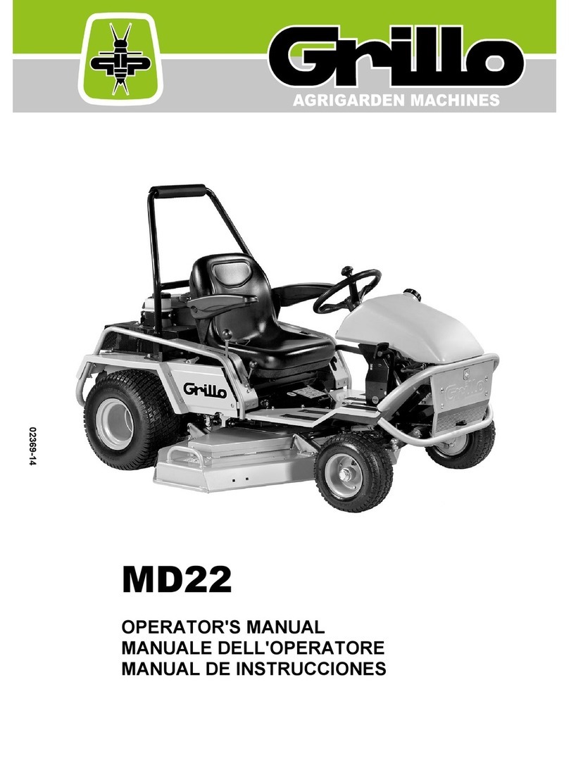
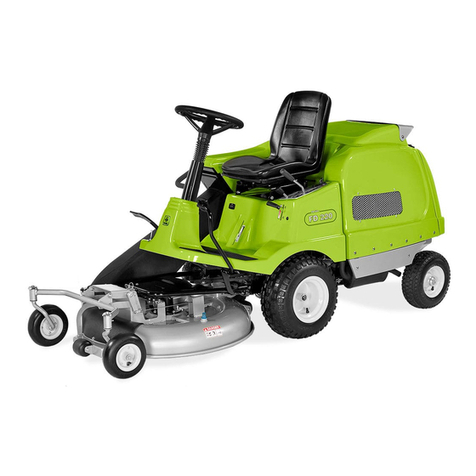
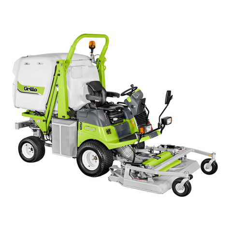
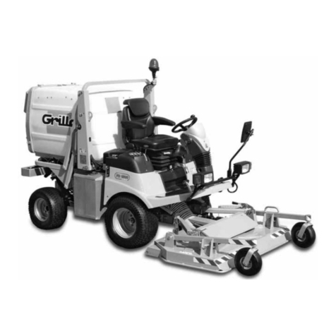
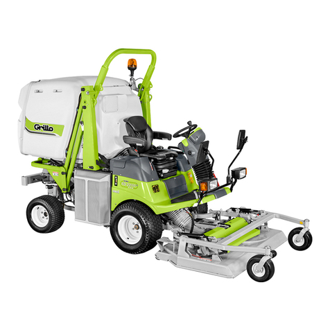
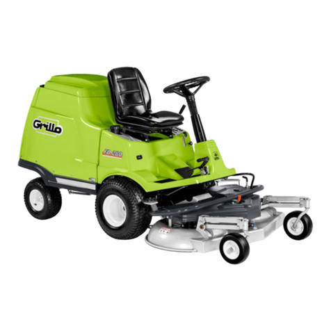
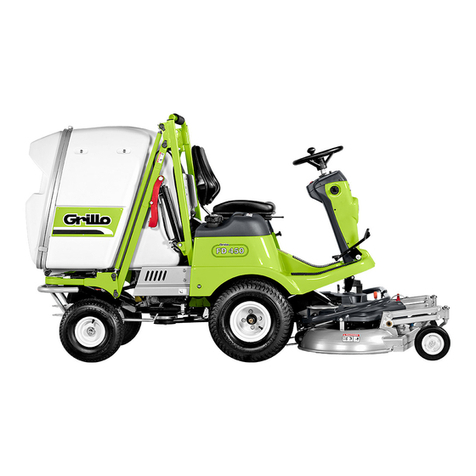
Grillo FD450 User manual

02401-19
FD450
OPERATOR'S MANUAL
MANUALE DELL'OPERATORE
MANUEL D'UTILISATION
BEDIENUNGSANLEITUNG
MANUAL DE INSTRUCCIONES
EERST DE HANDLEIDING


SUMMARY
Safety rules
Instructions
Warnings 5
Identification and servicing 6
Technical specifications 7
Putting the machine into service 8
Instructions for use 8
Maintenance and lubrication 2
Information and warnings 0
Pictures 04
EC Declaration of conformity
INDICE
Norme antinfortunistiche
Istruzioni
Avvertenze 2
Identificazione e assistenza 22
Caratteristiche tecniche 23
Messa in opera della macchina 24
Istruzioni d’uso 24
Manutenzione e lubrificazione 28
Etichette e avvertenze 0
Figure 04
Certificato di conformità CE
INDEX
Règles de sécurité
Instructions
Mises en garde 36
Identification et assistance 38
Caractéristiques techniques 39
Mise en service de la machine 40
Mode d’emploi 40
Maintenance et lubrification 44
Étiquettes et mises en garde 0
Illustrations 04
Certificat de conformité CE
VERZEICHNIS
Sicherheitsvorschriften
Anleitungen
Sicherheitsrelevante Hinweise 52
Identifikation der Maschine und Kundendienst 54
Technische Daten 55
Inbetriebnahme der Maschine 56
Betriebsanleitung 56
Wartung und Schmierung 60
Etiketten und Warnungen 0
Abbildungen 04
EG-Konformitätserklärung
ÍNDICE
Normas de seguridad
Instrucciones
Advertencias 69
Identificación y asistencia 7
Características técnicas 72
Puesta en servicio de la máquina 73
Instrucciones de uso 73
Mantenimiento y lubricación 77
Etiquetas y advertencias 0
Iustraciones 04
Certificado de conformidad CE
INDEX
Veiligheidsnormen
Instructies
Waarschuwingen 86
Identificatie en bijstand 88
Technische kenmerken 88
De maschine in werking stellen 89
Gebruiksinstructies 89
Onderhoud en smering 93
Labels en waarschuwingen 0
Illustraties 04
Certificaat van overeenstemming CE
I

SAFETY SYMBOLS - SIMBOLOGIA PER LA SICUREZZA - SYMBOLOGIE POUR LA SECURITE – SICHERHEITSSYMBOLE-
SIMBOLOGÍA DE SEGURIDAD
OPEN MANUAL- means that ou must read the operator's manual ver carefull .
MANUALE APERTO - significa che dovete leggere attentamente il manuale di uso e manutenzione.
MANUEL OUVERT – signifie qu'il faut lire avec attention le présent manuel.
OFFENES HANDBUCH – bedeutet, dass Sie die Gebrauchs- und Wartungsanleitung aufmerksam durchlesen müssen.
MANUAL ABIERTO – es decir que ha que leer mu atentamente el manual del operador.
CAUTION! - means that ou have to pa particular attention to the operation ou have to carr out, in particular if there is the
indication “DANGER”.
ATTENZIONE! - significa che dovete porre particolare attenzione all’operazione che dovete effettuare, in particolare se vi è anche
l’indicazione di “Pericolo”.
ATTENTION! - signifie qu'il faut faire particulière attention dans l'opération que vous allez faire, en particulier s'il a aussi
l'indication “DANGER”.
VORSICHT! - bedeutet, dass Sie besondere Aufmerksamkeit beim Durchführen des Vorgangs haben müssen, insbesondere wenn
auch der Hinweis “GEFAHR” aufgeführt ist.
ATENCIÓN! - es decir que ha que poner ma or atención en la operación a ejecutar si, en particular cuando ha también la
indicación “Peligro”.
INTERDICTION, YOU MUST NOT DO THAT! - means that it is absolutel forbidden to carr out the operations reported under this
s mbol because the could lead to mortal danger.
DIVIETO, NON FARE! - significa che non dovete assolutamente fare le operazioni riportate sotto questo simbolo, potrebbe
comportare un pericolo mortale.
INTERDICTION, NE PAS FAIRE! - signifie qu'il est absolument interdit d' effectuer les opérations reportées sous cette indication,
car elles pourraient conduire au danger de mort.
VERBOT, strengstens untersagt! - bedeutet, dass der Vorgang unter diesem S mbol absolut nicht durchgeführt werden darf, da er
zur einer lebensgefährlichen Situation führen könnte.
PROHIBICIÓN, NO LO HAGAN! - es decir que no ha que hacer absolutamente las operaciones bajo este símbolo, podría
comportar un peligro mortal.
NOTE, ou have to pa particular attention to the note put next to this s mbol
NOTA, dovete porre particolare attenzione alla nota posta accanto a questo simbolo.
NOTE, il faut faire attention particulière à la note mise à côté de ce s mbole.
ANMERKUNG, besondere Aufmerksamkeit muss auf die Anmerkungen neben diesem S mbol gelenkt werden.
NOTA, ha que poner atención particular en la nota puesta a lado de este símbolo.
You must not repair nor lubricate the machine with moving parts or with the engine put on.
Non riparare o lubrificare la macchina con organi in movimento o motore acceso
Ne pas réparer ou lubrifier la machine avec des parties en mouvement ou à moteur en marche.
Niemals bei bewegenden Objekten oder bei laufendem Motor Reparationen oder Einschmierungen durchführen.
No reparar ni lubrificar la máquina con órganos en movimiento o motor en marcha.
You must not smoke, light matches or lift flames, trigger frames nor cause sparks.
Vietato fumare, accendere fiammiferi o fiamme, lasciare fiamme libere o creare scintille.
Il est interdit de fumer, allumer des allumettes ou du feu, laisser des flammes libres ou de causer des étincelles.
Es ist untersagt zu Rauchen, Streichhölzer oder Feuer anzuzünden, Flammen auslösen oder Funken verursachen.
Prohibido fumar, encender cerillas o fuego, dejar llamas o crear chispas.
- 1
-
Use personal protective equipment.
Utilizzare mezzi di protezione individuali.
Utilisez l'équipement de protection individuelle.
Individuelle Schutzausrüstung benutzen.
Utilizar dispositivos de protección individual.

Take special care not to touch hot parts of the engine.
Prestate particolare attenzione a non entrare in contatto con parti surriscaldate del motore.
Veiller tout particulièrement à ne pas toucher des éléments surchauffés du moteur.
Achtung – keine heißen Motorteile berühren!
No tocar partes recalentadas del motor.
Tome muito cuidado para não entrar em contacto com as partes aquecidas do motor.
Engine exhaust fumes can cause sickness or death. If it is necessar to run an engine in an
enclosed area, use an exhaust pipe extension to remove the fumes. Alwa s tr to work in a well
ventilated area.
I gas di scarico possono causare malanni o morte. e è necessario mettere in moto un motore
in uno spazio chiuso, usare una prolunga tubo di scarico per far uscire il fumo. Lavorare in una
zona ben ventilata.
L’exhalation des gaz d’échappement peut être cause d’intoxication ou de mort. S’il est vraiment
nécessaire d’allumer le moteur à l’intérieur, appliquer au tu au d’échappement un autre tu au
extensible pour permettre la sortie des gaz. Il est toujours mieux de travailler en plein air.
Auspuffgase können Übelkeit oder Tod verursachen. Wenn es notwendig ist, einen Motor in
einem geschlossenen Raum laufen zu lassen, benützen ie eine Verlängerung, um das
Auspuffgas abzuleiten. Versuchen ie immer in einem gut belüfteten Raum zu arbeiten.
Los gases de escape pueden provocar enfermedades o muerte. De tener que poner en marcha
un motor en un espacio cerrado, usar una prolongación del tubo de escape para que salga el
humo. Trabajar en una zona bien ventilada.
Os gases de escape podem causar danos ou morte. Caso seja ncessário fazer com que o
motor funcione num espaço fechado, utilize uma extensão para o tubo de escape que os fumos
sejam expulso para o exterior. Trabalhe numa área bem ventilada.
Caution! Never touch moving pulle s or belts. The can be ver dangerous. Never do
maintenance with engine running.
Attenzione! Non toccare mai pulegge o cinghie in movimento, creano gravi danni alla persona.
Non fare manutenzione col motore in moto.
Attention! Ne jamais toucher ni poulies ni courroies en mouvement, elles peuvent provoquer des
accidents aux personnes. Ne pas faire l’entretien quand le moteur est en marche.
Vorsicht! Nie laufende Riemenscheiben oder Treibriemen anfassen, da es gefährlich ist. Nie bei
laufendem Motor Instandhaltung machen.
¡Atención! No tocar jamás poleas o correas en movimiento, porque pueden crear graves daños
a la persona. No efectuar el mantenimiento con el motor en marcha.
Atenção! Nunca toque nas polias ou correias em movimento devido ao alto risco de ferimentos.
Nunca faça a manutenção da máquina com o motor ligado.
A burst which separates the t re from the rim parts can cause serious injur or death.
La separazione fra pneumatico e cerchione, causata dall’esplosione del pneumatico, può
provocare serie ferite o addirittura la morte.
La séparation entre le pneu et la jante, provoquée par l’explosion d’une roue peut causer des
dommages, blessures ou la mort.
Die Trennung der Räder von den Felgen durch Explosion kann schwere Verletzungen oder den
Tod verursachen.
La separación entre el neumático la llanta producida por la explosión del neumático puede
provocar graves herida e incluso la muerte.
A separação entre o pneumático e o aro, provocada pela explosão do pneumático, pode causar
graves ferimentos ou até mesmo a morte.
Prevent batter explosions: keep sparks, lighted matches and open flames awa from the top of
the batter . Batter gas can explode.
Per prevenire l’esplosione della batteria, tenete scintille, fiammiferi accesi e fiamme lontani dalla
stessa. Il gas della batteria può esplodere.
Prévenir l’explosion de la batterie: tenir les étincelles, les allumettes et le feu loin de la batterie.
Le gaz de la batterie peut exploser.
Vorbeugung der Batterie-Explosion. Entfernen ie Funken, Zündhölzer und Flammen von der
Batterie. Das Batteriegas kann explodieren.
Para prevenir la explosión de la batería, mantener chispas, cerillas encendidas llamas lejos de
la misma. El gas de la batería puede explotar.
Para prevenir explosão da bateria ter centelhas, fósforos acendido e chamas longe da mesma.
O gás da bateria poderia explodir.
Handle fuel with care, it is highl flammable: Do not refuel machine while smoking, when
machine is near an open flame or sparks, or when the engine is running. Stop the engine.
Maneggiare il carburante con cura, è altamente infiammabile; non fate rifornimento mentre
fumate, o vicino a fiamme o scintille, o quando il motore è acceso.
Manier avec soin le carburant car c’est très inflammable. Ne pas remplir le réservoir si vous êtes
en train de fumer ou pendant que la machine est près du feu ou d’étincelles ou encore pendant
que la machine travaille. Arrêter le moteur.
Treibstoff vorsichtig handhaben, da er sehr entzündbar ist: beim Tanken nicht rauchen. Nicht
tanken, wenn die Maschine in der Nähe von Flammen oder Funken ist oder wenn der Motor
läuft. Immer den Motor abschalten.
Manejar el combustible con cuidado porque es sumamente inflamable; no repostar mientras se
fuma o cerca de llamas o chispas, o cuando el motor está encendido.
Manuseie o carburante com cuidado, pois este è altamente inflamável; não fume durante o
abastecimento da máquina ou enquanto o motor estiver ligado, não o aproximado de chama ou
de faíscas.

- 2
-

WARNING! SHARP PARTS. Keep hands and feet awa . Do not operate the mower over gravel
or foreign bodies which ma be sucked up and ejected b the blades, generating a danger. Keep
people awa . Remove the ke and read the instruction manual before attempting to carr out
an maintenance or repairs to the machine.
ATTENZIONE! ORGANO TAGLIENTE. Tenere lontano mani e piedi. Non lavorare col rasaerba
sopra alla ghiaia o corpi estranei che possono essere aspirati e centrifugati dalle lame risultando
molto pericolosi, tenere lontano le persone. Togliere la chiave e leggere le istruzioni prima di
effettuare qualsiasi operazione di manutenzione e riparazione.
ATTENTION! ORGANE TRANCHANT. Eloigner les mains et les pieds. Ne pas utiliser la
tondeuse sur le gravier ou sur des corps qui peuvent être aspirés et centrifugés par les lames et
devenir très dangereux. Les personnes doivent se trouver à une certaine distance. Enlever la clé
et lire les instructions avant toute opération de maintenance et de réparation.
ACHTUNG! CHARFE KLINGEN. Hände und Füße fernhalten. Beim Mähen nicht über
chotter, teine oder andere Fremdkörper fahren, da diese durch die Drehbewegung der
Messer angesaugt und weggeschleudert werden können (Verletzungsgefahr). Nicht in der Nähe
von anderen Personen mähen. Vor jedem Wartungs- bzw. Reparatureingriff den tartschlüssel
abziehen und die Gebrauchsanleitung durchlesen.
¡PELIGRO! ÓRGANO CORTANTE. Mantener alejados los pies las manos. No limpiar la
herramienta con el motor en marcha. ¡Peligro! Expulsión de objetos: mantener alejadas a las
personas. Atención: quitar la llave leer las instrucciones antes de efectuar cualquier operación
de mantenimiento o reparación.
ATENÇÃO! Órgão cortante. Ficar longe com pés e mãos. Não trabalhar com a máquina sobre
cascalho ou objetos que podem ser aspirados e centrifugados gerando perigo, manter-se longe
das pessoas.
Tirar a chave de ignição e ler as instruções antes de efetuar qualquer operação de reparo ou
serviço.
Warning! Cutting edges, keep our hands and feet awa .
Do not clean the attachment when the engine is running.
Attenzione! Organo tagliente, tenere lontano piedi e mani.
Non pulire l'attrezzo col motore in moto.
Attention! Organe tranchant, ne pas approcher main et pieds.
Ne pas netto er le moteur quand le moteur est en marche.
Achtung! Schneidende Klinge, Hände und Füße fernhalten.
Niemals bei laufendem Motor reinigen.
DANGER! READ THE INSTRUCTION MANUAL. KEEP SAFETY DISTANCES.
PERICOLO! LEGGERE IL MANUALE D’ISTRUZIONE. TENERE LONTANO LE PERSONE.
DANGER! LIRE LE MANUEL D’INSTRUCTIONS. RESPECTER LES DISTANCES DE
SÉCURITÉ
GEFAHR! DIE GEBRAUCHS ANLEITUNG DURCHLESEN. NICHT IN DER NÄHE VON
ANDEREN PERSONEN MÄHEN.
PELIGRO! LEER LAS INSTRUCCIONES. MANTENER ALEJADAS LAS PERSONAS.
PERIGO! LER O MANUAL DE INSTRUÇÕES. MANTER AS PESSOAS AFASTADAS.
Before using the machine, it is mandator to put on the appropriate individual safet devices:
bod protection, protection gloves, securit shoes, ear protection.
Prima di utilizzare la macchina, è obbligatorio indossare gli appositi dispositivi di sicurezza
individuali: protezione del corpo, guanti di protezione, calzature di sicurezza, protezione
dell’udito.
Avant d’utiliser la machine, il est obligatoire de mettre les dispositifs individuels de sécurité
appropriés: protection du corps, gants de protection, chaussures de sécurité, protection de
l’ouïe.
Vor dem Gebrauch der Maschine ist es vorgeschrieben, die geeignete persönlichen
chutzkleidung anzuziehen: Körperschutz, chutzhandschuhe, icherheitsschuhe,
Gehörschutz.
Antes de utilizar la máquina es obligatorio ponerse los dispositivos individuales de seguridad
apropiados: protección del cuerpo, guantes de protección, calzado de seguridad, protección del
oído.
- 3
-

FD450/ Translation of the original instructions
FD450
OUTFRONT MOWER WITH OLLE TION
Dear Customer,
Thank you for purchasing our Grillo FD450. We are confident that this machine ill fully satisfy all
your requirements. To use and maintain the mo er at its best, e urge you to read and observe
carefully the instructions given in this handbook; this ill ensure the best possible results and ill
also safeguard your investment. Please keep this handbook in a safe place. It should accompany
the machine throughout its orking life.
ATTENTION! Please read carefully before starting the engine. The
following warnings are important for the operator's safety!
WARNINGS
Caution is the main safeguard in preventing accidents. We urge you to read the follo ing arnings
before using the mo er and before starting any ork at all. Improper use of the mo er and its
equipment can be dangerous; to minimise risks, al ays observe the necessary precautions set out
belo :
1) Read the hole of this manual before using the mo er for the first time.
2) Pay particular attention to the arnings and safety labels placed around the mo er.
3) The mo ers blades are very dangerous hen rotating; never place your hands or feet
underneath the mower deck.
4) Before allo ing others to use the machine, make sure they are a are of the safety
precautions and ho to use the machine.
5) Before starting work always change into suitable working clothes, gloves, boots and
goggles.
6) Wear special acoustic protections (ear-defenders) during ork.
7) Before starting the machine, make sure there are no people around it; especially children.
8) Before operating the machine in reverse, make sure there are no people or obstacles in the
ay.
9) Check the condition of the ground before mo ing. Make sure there are no stones, sticks or
other objects hich could be run over and become very dangerous if projected.
10) If any impact ith a foreign object occurs, disengage the blade, turn off the engine, remove
the ignition key and examine the mo er; if the machine vibrates, have it repaired.
11) Before dismounting the mo er, disengage the PTO, turn off the engine, remove the ignition
key and lo er the deck to its lo est position.
12) Al ays drive slo ly along uneven paths.
13) Keep the speed do n hen driving do n slopes.
14) Al ays turn slo ly hen driving do nhill.
15) The user is al ays liable for any damage caused to third parties.
16) Deformed or damaged blades must al ays be replaced, never just repaired.
17) Al ays use original GRILLO spare parts and accessories.
18) Only ork in daylight or under effective artificial lightning.
19) Only store fuel in suitable containers designed for the purpose.
20) Be very careful hen orking close to a road.
21) Lift and empty the grass catcher only hen the machine is motionless and on a flat ground.
22) Allo the engine to cool before putting the machine a ay in a closed environment.
IMPROPER USE TO BE AVOIDED
23) Do not allo passengers to ride on the machine.
24) Do not allo under-age people to operate the machine: its use is prohibited to children under
16 years old.
25) Do not operate the machine hen tired or after drinking alcohol.
26) Do not operate the mo er near to ditches or verges hich could collapse under the eight of
the machine, especially hen the surface is loose or et.
27) Do not allo any fuel spillage and, after filling the tank, ipe a ay any spilt fuel before starting
5

FD450/ Translation of the original instructions
the engine.
28) Do not tamper with any safety devices or disable them.
29) Do not change the engine settings, especially the maximum number of revs.
30) Do not rest heavy loads on the seat, the starter safety device could become disengaged.
31) Never attempt any adjustment or cleaning ith the engine running.
32) Never allo anyone to check the machine hile you are seated at the controls ith the engine
running.
33) Do not move the machine ithout the deck, because it may turn over and be very dangerous.
34) Do not lift the grass-catcher hen the machine is moving.
35) Replace a orn or damaged exhaust.
FURTHER SAFETY ADVI E
The above mentioned arnings could never be enough to avoid all risks if the operator does not
use the mo er correctly. For your safety e therefore give you the follo ing advice:
36) The mower blades are very dangerous when rotating, never put your hands or feet
underneath the mower deck.
37) Do not engage reverse gear at full po er.
38) It is dangerous to operate the steering heel abruptly ith the engine at full po er.
39) Fill the tank ith fuel before starting the engine. Only refuel outdoors, al ays turn off the
engine, keep a ay from sparks or naked flames, do not smoke! Al ays replace the cap on the
fuel tank and those on fuel containers properly.
40) If the fuel tank has to be emptied, only do so outdoors.
41) Never mo over gravel.
42) If you have children, hide the ignition key after using the machine.
43) CAUTION: to avoid the risk of fire, keep the engine compartment, exhaust, discharge outlets,
battery, tank area and fuel pipes free of grass, leaves, dirt etc...
44) Do not store the machine inside any building here the engine fumes can reach naked flames,
sparks or bare electrical ires.
45) When the mo er deck is raised, move slo ly and for short distances only.
46) Remove the implements, turn off the engine and disconnect the spark plugs:
a) before cleaning obstructed points.
b) before checking or repairing the mower.
c) if the machine hits a foreign body (check the mower deck to see if it is damaged, make
repairs before you operate again).
d) if unusual vibrations occur, stop and inspect the machine. ontact your nearest
authorised service centre if you need help.
IDENTIFI ATION AND SERVI ING
IDENTIFI ATION
The Grillo FD450 has an ID plate sho ing the serial
number, located underneath the seat. Al ays state the
serial number hen ordering spare parts or asking for
technical assistance
AFTER-SALES SERVI E
This handbook provides instructions for using the mo er. For correct servicing, contact your local
dealer.
SPARE PARTS
Original spare parts should al ays be used, as they are your only guarantee of safety and
interchangeability. When ordering, al ays state the machine's serial number and the code number
of the spare part required. For engine parts, follo the instructions provided in the specific manual.
GUARANTEE
This guarantee is given in compliance ith current la . The dealer ill give the customer a copy of
the registration card of the machine, hich they ill print from the Grillo ebsite. For the engine,
6

FD450/ Translation of the original instructions
the guarantee of the relative manufacturer ill apply.
RE OMMENDED SPARE PARTS
1 set of mo er blades
1 set of belts
1 engine air filter
1 engine oil filter
1 throttle cable
HOW TO ORDER SPARE PARTS
Al ays state the machine's serial number and the code number of the spare part required. Contact
your local Grillo service centre. For further information, our address is:
GRILLO S.p.A.
Via Cervese 1701 - 47521 CESENA (FC)
Tel. 0547.381.333 / Fax 0547.632.011
Web site: .grillospa.it / e-mail: [email protected]
TE HNI AL SPE IFI ATIONS
ENGINE: - BRIGGS & STRATTON, 7220 Professional Series, net po er 18HP (gross po er
max.
22HP), OHV, 656 cc t in-cylinder petrol version ith oil pump.
STARTER: electric ith 12V battery.
GEARBOX: hydrostatic transmission ith differential lock.
DIFFERENTIAL LO K: mechanical ith pedal control.
SPEED: 0 – 11km/h (for ard) and 0 – 6km/h (reverse) through pedal control device.
FUEL TANK: 17 litres – RESERVE TANK: 2,5 litres.
UTTING DE K: frontal ith 3 blades for a total idth of 1190 mm and equipped ith solid
heels.
UTTING WIDTH: 1130 mm (± 51,2”).
ELE TRI UTTING HEIGHT ADJUSTMENT: from 25 mm (± 0,98”) to 90 mm (± 3,54”).
LUT H: electromagnetic for PTO ith magnetic blade brake.
DRIVING SYSTEM: ith steering heel, hydraulic drive, for ard and reverse gears engaged
through
pedal.
SEAT: ith adjustable suspension.
GRASS- AT HER: 450 litres ith full grass catcher motorized micro-s itch.
GRASS- AT HER DIS HARGE AND DE K LIFTING HYDRAULI ALLY OPERATED
THROUGH AN
ELE TRI BUTTON.
DIS HARGE HEIGHT: 170 cm (± 67”). REAR EJE TION: 45 cm (± 17,7”).
TYRES: front: 20×10.00-8 (1 Bar); rear: 15×6.00-6 (1,2 Bar).
PARKING BRAKE: disk brake.
STEERING RADIUS: 25 cm.
HOURLY UTTING APA ITY: 8000 m2/h (indicative).
7

FD450/ Translation of the original instructions
IN LUDED IN THE MA HINE: to bar.
ATTA HMENTS: mulching kit.
SIZE & WEIGHT: Length: 2680 mm - Width: 1190 mm - Height: 1460 mm ith lo ered roll-bar
– 1940 mm ith raised roll-bar.
Weight: 450 kg
PUTTING THE MA HINE INTO SERVI E
1) Check that the machine is complete and has not been damaged in transit.
2) Check the engine oil level, use (SAE30).
3) Check the tyre pressure:
Front heels 20×10.0 – 8 (1 BAR)
Rear heels 15×6.0 – 6 (1,2 BAR)
4) Check the battery voltage; it must be at least 12 Volts. Charge the battery if necessary.
IMPORTANT!!! When fitting the battery, ensure that the poles are correctly connected. Never
start the engine if the battery is not connected.
5) Important: the hydraulic oil level indicator is placed on the right side side of the tank (fig.14, ref.
A). Exclusively use ISO VG 46 (OSO 46) oil.
BATTERY – WARNING!
The gases released by the battery are explosive, keep it a ay from sparks or naked lights. Check
the terminals periodically and keep them greased ith Vaseline.
RUNNING-IN – WARNING!!
Change the engine oil after the first 20 orking hours. Use SAE30 API SJ oil, 1,9 litres. Change
the oil in the hydrostatic axle after the first 50 orking hours. Check that there are no oil leaks or
loose scre s, especially the blade fixing scre s. IMPORTANT: the central screw of the right
blade has a left-hand thread.
INSTRU TIONS FOR USE
Before starting the engine, al ays check that:
the hydrostatic transmission cooling fins are clean (fig. 18).
the engine cooling grids are clean (fig.13, A).
the engine oil is at the correct level: scre the cap to check the level (fig.13, B)
the speed selection pedal is not depressed (fig.1, n.1);
the PTO s itch is OFF (fig.2 n. 3);
the air filter is clean (fig. 6, A).
to inspect the engine, lift the grass catcher and insert the red safety devices on the hydraulic
cylinders (fig. 40, A).
To release the safety devices, press the button (fig.39, A) and hook them on the chrome cylinder
rod. The safety devices ill hold their position thanks to a magnet.
the cutting deck is clean (fig. 26).
the grid inside the grass-catcher is clean (fig. 7, B).
Fill the fuel tank, using a funnel fitted ith a very fine mesh filter (fig. 5, n.14).
Adjust the seat ith the aid of the lever (fig.3, no.10).
STARTING THE PETROL ENGINE
Push the throttle to half- ay (fig.3, n.8). If the engine is cold, activate the choke (fig.3, n.9). Turn
the ignition key on the dashboard (fig. 4, n. 15). Once the engine has started, release it, deactivate
the choke and ait a fe minutes for the engine to arm up.
8

FD450/ Translation of the original instructions
STARTING WORK
Speed up the engine by pushing the throttle half- ay (fig. 3, n. 8), then engage the PTO s itch (fig.
2, n.3). Adjust the cutting height using the button (fig.2 n.4). The button (fig. 5, n. 11) is used to
raise the mo er deck. During ork the mo er deck must be set in the floating position (“FLOAT”).
AUTION: Do not engage the cutting blades ith the engine running at maximum r.p.m, engage
them only at half speed and outside the area to be cut.
FRONT HEADLIGHT
To s itch on the headlight, put the ignition key in the second position (fig. 4, no. 15). IMPORTANT:
Only use the headlight ith the engine running to avoid battery discharge.
IMPORTANT
1) Adjust the for ard speed in order to avoid overloading the deck hen at ork and al ayscut
ith the engine at maximum r.p.m..
2) Al ays keep the blades sharp. In case of ear sharpen or replace them as required.
Gently press the for ard pedal (fig.1, n.1) and start ork. Push the pedal to position A to travel
for ard and to position B to travel in reverse. If the pedal is released, the machine immediately
stops. Lever (fig.3, n.7) is the parking brake; in the “P” position (fig. 2) the parking brake is
engaged. When the grass-catcher is full the blades automatically disengage. The grass-catcher is
equipped ith an inner sensor that automatically disengages the blades hen the grass-catcher is
full (fig.38, A). The grass-catcher has therefore to be emptied. It can be emptied directly from the
driver's seat using the buttons (fig. 5, n.12 to raise the grass-catcher and n.13 to empty the grass-
catcher). The grass-catcher door opens automatically. The grid inside the grass-catcher must
al ays be kept clean to improve grass collection and to prevent clogging (fig. 7, B). During summer
and in very dusty environment it is recommended to fit the plastic protection plate (fig. 7A, A) inside
the grass-catcher. This plate and the necessary scre s are delivered ith the machine.
LOSING OF THE GRASS- AT HER
The grass-catcher can be checked opening the door (fig. 8, A). The closing can be regulated (fig.
8, B). The grass-catcher door opens automatically hen the operator uses the button from the
driver's seat. To keep the grass catcher door open use the rod (fig. 7, A). AUTION: Do not
engage the blades hen the grass catcher door is open.
TIPS FOR EFFI IENT USE
1. Check the ground condition before mo ing. Make sure there are no stones, sticks or other
foreign objects.
2. When mo ing, keep the engine at full revs and adjust the speed to suit the height of the
grass. Take care hen you come to thick clumps of tall grass; slo do n if necessary.
3. Sharpen the mo er blades frequently; the cut ill be better and the engine ill be under less
strain.
4. Engage the blades a fe metres outside the area to be cut.
5. Al ays keep the engine at full r.p.m. hen mo ing; if the engine revs drop, slo do n for a
moment to allo the engine to recover its r.p.m.
6. For the best la n appearance, alternate one longitudinal and one transverse cut, both at the
same height.
7. If the duct tends to become clogged ith grass, reduce the for ard speed as it may be too
high for the la n condition. If the problem persist, probable causes are blunt blades, dented
fins profile, slack belt or a clogged grass catcher grid.
8. If the grass is very long, it is best to cut in t o passes, the first ith the blades at the highest
level, perhaps orking on reduced idth, and the second at the final height required.
9. Take great care hen cutting close to bushes and lo kerbs hich might damage the edge of
the back and the blades.
10. Engage the parking brake once ork is finished (fig.3, n.7).
UTTING POSITION
To adjust the cutting height, use the button (fig. 2 n.4). On rough or uneven ground, al ays ork
9

FD450/ Translation of the original instructions
ith the deck set at its highest cutting position in order to avoid damage to the blades. On the rear
part of the mo er deck three anti-scalp heels are fitted (fig. 26, A); their height can be adjusted
through the fixing holes.
BLADE ENGAGEMENT
The engagement or disengagement of the blades is effected by operating the s itch (fig. 2, no. 3).
When rotation is engaged the engine must be running at medium r.p.m and the machine must be
outside the area to be cut. Never start the blades ith the engine running at maximum rpm. The
machine is fitted ith an electromagnetic clutch hich also stops the blades during
disengagement. The blades should stop ithin 5 seconds from disengagement. Should this not be
the case, adjust the three nuts of the electromagnetic clutch placing a 0.3 mm feeler gauge under
the brake plate. N.B. This operation must be carried out by an authorised service center only.
Do not use the machine if the blades do not stop within 5 seconds after disengagement with
the engine at max. rpm.
OPERATOR ROLL OVER PROTE TION (ROPS)
Pay greater attention hen orking on slopes. IMPORTANT:
- Do not remove the ROPS from the machine
- Al ays keep the ROPS in perfect orking conditions, frequently check its fastening elements.
- Make sure the ROPS is not damaged during ork.
- Should the ROPS be damage, never repair it nor modify it. It must be replaced.
FOLDABLE ROPS
AUTION: To avoid injury or death from roll-over keep the roll-bar in the raised lock
position and use the seat belt.
Ensure that the seat is secured ith the seat latch. There is no roll-over protection hen the roll
bar is in the do n position. Please note:
- ROPS is a safety system
- Al ays ear the safety belt hen the roll-bar is in the raised lock position.
- Lo er the roll-bar only hen absolutely necessary.
- Do not ear the seat belt hen the roll-bar is in the do n position.
- Do not operate the machine on uneven ground or on a hill side ith the roll-bar in the do n
position.
- Check carefully for overhead clearances (i.e. branches, door ays, electrical ires) before driving
under any
objects and do not contact them.
- Raise the roll-bar as soon as clearance permits.
To lo er the roll-bar follo the procedure described belo :
1) Park the machine on a level surface.
2) Disengage the PTO, lo er the mo er deck, and engage the parking brake.
3) Shut off the engine and remove the key.
4) Remove the bolts from the roll-bar (fig. 47, ref. A).
5) Lo er the upper part of the roll-bar and insert the bolts (fig. 48, ref. B).
6) Remove the bolts from the lo er part of the roll-bar (fig. 49, ref. C – D).
7) Lo er the hole roll-bar structure and insert the bolts (fig. 50, ref. E).
Important: Lower the roll-bar only when absolutely necessary.
To raise the roll-bar follo the procedure described belo :
1) Park the machine on a level surface.
2) Disengage the PTO, lo er the mo er deck, and engage the parking brake.
3) Shut off the engine and remove the key.
4) Remove the bolts from the lo er part of the roll-bar (fig. 50, ref. E).
5) Lift the hole roll-bar structure and insert the bolts (fig. 49, ref. C – D).
6) Remove the bolts from the roll-bar (fig. 48, ref. B).
7) Lift the upper part of the roll-bar and insert the bolts (fig. 47, ref. A).
10

FD450/ Translation of the original instructions
SEAT SUSPENSION AND SEAT TILTING ADJUSTMENT
Use the plastic knob (fig. 51, ref. F) to adjust the seat suspension, by turning it clock ise or
anticlock ise to make the suspension harder or softer. The seat is tilted pushing the lever behind
the seat (fig. 52, ref. G).
SLOPES
When orking on slopes and/or on uneven and et grounds that could cause the roll over of the
machine, it is absolutely necessary to use the machine ith the cutting deck lo ered to the ground
into orking position, roll-bar locked in the raised position and fastened seat belts. If possible
al ays travel up and do n rather than across slopes. When turning, take care that the heels on
the uphill side do not meet any obstacles (stones, logs, roots, etc.) hich might make you lose
control of the machine. If the drive heels tend to slip, slightly raise the mo er deck using the
hydraulic button or adjust the t o floating springs (fig. 10, A) to put more eight on the for ard
heels to gain more traction. Al ays assess the orking conditions and take care on damp ground
or et grass since the machine might slip. When going do nhill, start off slo ly and try not to drive
over dry or cut grass because the heels may lose grip. Never use this machine on slopes of more
than 12° (21%). If the heels tend to slip, use the differential lock (fig.1 n.2).
HOURMETER
The machine is fitted ith an hour meter ith three different functions:
1) It al ays sho s the no. of hours orked, even hen the key is not inserted.
2) It displays the no. of hours to the next engine oil change (OIL CHANGE IN...HS). The first oil
change must be carried out after the first 20 orking hours then every 100 orking hours. The
indicator “OIL CHANGE” flashes automatically hen it is necessary to change the oil.
3) It displays the no. of hours to the next lubrication (LUBE IN...HS). Lubrication must be carried
out every 40 orking hours. The indicator “LUBE” flashes automatically hen lubrication must be
carried out.
By pushing the hite button, you can choose the function to be displayed on the hour meter.
4) To reset the hour meter after an engine oil change or after lubrication proceed as follo s:
Push the button until the relative alarm flashes (OIL CHANGE IN...HS or LUBE IN...HS). Then
keep the button pushed for 6 seconds until the meter stops flashing.
SAFETY DEVI ES
The engine should stop henever:
- the operator leaves the seat hile the parking brake is disengaged and the PTO is engaged.
- the operator presses the for ard pedal hen the parking brake is engaged.
The engine ill not start if:
- the blades are engaged;
- the operator is not sitting in the driving seat and the parking brake is not engaged;
- the for ard pedal is not in the stop position;
11

FD450/ Translation of the original instructions
MAINTENAN E AND LUBRI ATION
AUTION!
- Disconnect the spark plugs before performing any cleaning, maintenance or repair
operation. Always wear suitable clothing and working gloves.
- When the machine or part of it is lifted to carry out maintenance operations, always
remember to use suitable fixing tools such as holders and safety locks.
- When carrying out maintenance operations and/or when the machine is tilted without
safety locks or supports, never leave it unguarded in places where inexperienced people
and children could have easy access to it.
- Protect the environment: carefully dispose of used oils, petrol and any other pollutant
product!
- Effective maintenance and correct lubrication help to keep the machine fully efficient.
ENGINE
For the lubrication intervals, follo the instructions outlined in the engine manual. For the INTEK
7220 professional series engine use SAE 30 oil (quantity 1,9 litres). Frequently check the engine
oil level (fig. 13, B). Replace both the engine oil and filter (fig. 13, C) as outlined in the maintenance
table. To unscre the oil drain plug (fig. 11, A) insert a rubber pipe then unscre the end part of
the plug and let the oil drain into a container; use a counter-key to hold the fixed component of the
plug. Remember to protect the belts, they must not come in contact ith the oil. The first
precaution is to ensure that the engine is correctly serviced with the air filter, cooling fins
and cylinder head clean and the oil at the correct level. Check the air filter every 4 hours or
even more often in very dusty environments (fig. 6, A). Check that the engine cooling intake grid is
al ays clean (fig. 13, A).
HYDROSTATI AXLE
Visually check the oil level in the expansion tank (fig. 16, B). When the engine is cold the oil level
must be 1 cm above the bottom of the expansion tank. Frequently clean the hydraulic motor
cooling fins and the fan especially in summer and every 4 hours in very dusty environments
(fig.17). Replace the oil after the first 50 hours, and then every 200 hours. Exclusively use SAE
20W50oil, 2,5 litres. To replace the oil follo the instructions belo :
1. Unscre both drain plugs (fig. 15, A – B)
2. Remove the left cover to gain access to the oil refilling cap placed on the tank (fig. 16, A).
3. Unscre the oil filter of the hydrostatic transmission and clean it. Replace if necessary (fig. 12,
A).
4. Inside the tank there is a hydraulic filter (fig. 14, B). This filter does not require any special
maintenance.
5. Once the oil has been totally drained, tighten both plugs again (fig. 15, A – B).
6. Activate the by-pass lever (fig. 27, A) by pushing the lever to ards the machine to let the oil
drain from the main hydrostatic circuit.
7. Remove the connection on the hydrostatic transmission (fig. 19, B) and fill the hydrostatic
chamber ith oil (fig. 18 – HYDRO CHAMBER).
8. Remove the cap on the hydrostatic transmission (fig. 19, A) and fill the gear chamber ith oil
(fig. 18 – GEAR CHAMBER).
9. Scre the cap and remount the expansion pipe (fig. 19, C) and make sure the oil level is 1 cm
above the bottom of the expansion tank (fig. 16, B).
10. Purge the hydrostatic transmission follo ing the instructions belo :
a) put the machine in a steady, safe position ith the front heels raised from the ground,
make sure the by-pass valve is activated, s itch the engine on, ait a fe minutes then repeatedly
engage the for ard and the reverse gear by pressing the pedal (fig. 1, n. 1).
b) deactivate the by-pass valve (fig. 27, A) by pulling it and repeatedly engage the for ard
and reverse gear by pressing the pedal (fig. 1, n. 1).
c) Put the machine on the ground again and check if the machine moves for ard and stops
correctly: in case of poor performance, loss of traction or noises coming from the hydrostatic axle,
repeat the purge (see point no. 10I.
11. Visually check the oil level in the expansion tank (fig. 16, B). When the engine is cold the oil
level must be 1 cm above the bottom of the expansion tank.
12

FD450/ Translation of the original instructions
IMPORTANT: this operation has to be carried out in a clean environment to prevent
impurities or ground residues from entering the hydrostatic axle and causing damage.
Therefore, we recommend the replacement of oil into the hydrostatic axle to be carried out
only by a Grillo authorised service centre.
HYDRAULI IR UIT
Frequently check the hydraulic oil level in the tank hen the engine is cold and the grass-catcher is
closed. Use OSO 46 hydraulic oil, total amount of 3,5 litres.
IMPORTANT: Replace the hydraulic oil after the first 500 orking hours then every 1000 hours. To
drain the oil use the appropriate drain plug (fig. 14, C).
Replace the oil before 500 orking hours only if:
- the oil is black
- the oil has a hitish colour (it has been contaminated ith ater);
- there are black residues (partial oil deterioration).
REAR WHEEL AXLE
Grease the rear heel pivot pins every 20 hours (fig. 41, A).
DIFFERENTIAL LO K
To engage the differential lock, press the pedal (fig. 1, n.2). Adjust the control cable and lever so
that the differential lock can be correctly engaged and disengaged (fig. 9). When releasing the
pedal, the differential lock must disengage. Do not use the differential lock hen changing direction
because the differential lock components could be strained.
SHARPENING THE BLADES
A blunt blade pulls at the grass, giving it an unsightly appearance. The cutting edges of both
blades must therefore al ays be kept sharp and orn blades must be replaced. To sharpen the
blades first remove the mo er deck (fig. 26) then follo the instructions belo :
1) Position the mower deck in its lowest cutting position.
2) Remove the protection guard above the deck by unscre ing both ing nuts (fig. 25).
3) Remove the pin (fig. 25, A).
4) Turn the lever anti-clock ise (fig. 25, B).
5) Remove the PTO belt (fig. 25, C).
6) Detach the ire of the electric ire (fig. 25, F).
7) Release the fork (fig. 31, B), pull the deck for ard and set it vertical (fig. 26). It is recommended
to open the grass catcher and take off the discharge chute. (fig. 32, A).
Worn blades lose their cutting efficiency and tend to become unbalanced, causing the mo er to
vibrate. If the unbalance persists even after sharpening, check the balance by inserting a
scre driver in the hole in the centre of the blade and hold up, grind the blade until it remains
horizontal and is therefore balanced. To remove a blade, take hold of it firmly, earing safety
gloves, and undo the centre bolt (IMPORTANT: the right hand blade bolt has a left thread).
AUTION!
Al ays replace damaged or orn-out blades; never attempt to repair them! ALWAYS USE
ORIGINAL BLADES!
AUTION!
In order to reassemble the cutting deck, you have to fit together the cutting deck lead (fig.23, A)
ith the one hich is located on the machine, bet een the heels, in the centre.
LUBRI ATION WITH GREASE
Follo the lubrications points scheme (fig. 41A – 41B). Lubricate ith grease every 40 hours the
rear axle joints, pedals and the grass-catcher lifting arms.
13

FD450/ Translation of the original instructions
UTTING DE K ADJUSTMENT
A level deck is essential for a uniform cut. With the mo er on a flat surface, check that the tyre
pressures are correct and check the float spring tension (fig. 10, A). If a satisfactory parallel set-up
cannot be achieved, adjust the register (fig. 20, A). To adjust the mo ing height, place t o 25 mm
shims at the sides under the edge of the deck and put the deck in its lo est position using the
button on the dashboard. Use the scre (fig. 24, B). Before carrying out this procedure loosen the
t o scre s (fig. 24, A). at the rear part of the mo er deck, t o anti-scalp heels are fitted (fig. 34,
C). Their height can be adjusted through the three fixing holes.
DRIVE BELTS – HYDROSTATI AXLE
These belts are self-adjusting and do not require any adjustment. Simply check the tension of the
springs. To replace these belts, release both tension springs (fig. 22, A – B).
PTO BELT
Caution: This belt is special, only use original belts. To replace the PTO belt, follo the instructions
belo :
1) Remove the protection guard above the deck by unscre ing the t o scre s (fig. 25).
2) Remove the pin (fig. 25, A)
3) Turn the lever anti-clock ise (fig.25, B)
4) Remove the PTO belt (fig. 25, C)
5) When refitting the belt, make sure the belt guide is located inside the t o sides of the belt (fig.
37, A).
The PTO belt does not need to be regulated because it is self-adjusting.
UTTING DE K BELT
This belt is a double A section and allo s the blades to counter-rotate. The belt tension is self-
adjusting thanks to the spring (fig. 34, A). The spring must have 130 mm length (coils length). To
replace the cutting deck belt follo the instructions belo :
1. Set the mo er deck at its lo est position.
2. Remove the plastic cover placed over the mo er deck by unscre ing both ing nuts.
3. Remove the pin (fig. 25, A)
4. Turn the lever anti-clock ise (fig. 25, B)
5. Remove the PTO belt (fig. 25, C)
6. Detach the ire of the electric ire (fig. 25, F)
7. Release the fork (fig. 31, B) and pull the deck for ard. It is recommended to open the grass
catcher and remove the load chute (fig. 32, A).
8. Remove the pulley by unscre ing the central scre (fig. 25, E).
9. Remove the cutting deck protection frame loosening the scre s (fig. 31, C).
10. Unhook the spring (fig. 34, A);
11. Remove the belt and fit a ne one (fig. 34, B), follo ing the diagram.
USE ORIGINAL BELTS ONLY!
HYDRAULI PUMP BELT
The hydraulic pump belt is self-adjusting (fig. 21). To replace this belt, unhook the spring (fig. 21,
A) and unscre the t o scre s fixing the pump support plate (fig. 21, B).
14

FD450/ Translation of the original instructions
MAINTENAN E SUMMARY TABLE
PRO EDURE EVERY 8
HOURS
AFTER
20
HOURS
EVERY
50
HOURS
EVERY
100
HOURS
EVERY 200
HOURS
Engine oil check the level ●
change ● ●
Air filter
check ●
replace ٭
Hydrostatic
axle oil
check the level ● ●
replace
(first
change)
●
●
Spark plug
check/adjust ●
replace ●
Check that the engine cooling grid
is clean ●
Check that the hydraulic engine
cooling fins are clean ●
Check that blades are ell-
sharpened and ell-fixed ●
Lubricate ith grease ● ●
● recommended procedure
٭ procedure to be carried out if necessary
TROUBLESHOOTING-GUIDE
PROBLEM
CAUSE REMEDY
With the key in the ON position, the instrument panel remains off
– Battery not supplying any po er – Check the connecting cables
– Charge the battery
– Replace the fuse
The instrument panel comes on, but ith the key in the ON position, the starter motor does not turn
– Battery not supplying enough po er – Charge the battery
– Start-up not enabled – Travel pedal in STOP position
– Disengage the blades
– Sit in the driving seat
Engine difficult to start or runs unevenly
– Carburettor problems – Clean or replace the air filter
– Adjust the carburettor (refer to the motor
handbook)
15

FD450/ Translation of the original instructions
– Sediment or dirt in the fuel – Empty the tank and use fresh petrol
– Check the fuel filter and replace if
necessary
The starter motor turns but the engine ill not start
– No petrol flo – Check that the choke is on
– Check level in fuel tank
– Check the fuel filter and replace if
necessary
– Check that the fuel vent hole is not
blocked
– Ignition system fault – Check that the spark plug cap is on
properly
– Check that the electrodes are clean and
the
gap is correct
Engine revs fall during mo ing
– Travel speed too high for – Decrease speed
mo ing height – Raise the deck a fe settings
When the blades are engaged, the engine cuts out
– Engagement not enabled – Check the blade engagement micro-
s itch
– Operator must be seated in the driving
seat;
Uneven cutting and poor collection
– Cutter deck not parallel ith the ground – Check tyre pressures
– Adjust the deck until parallel
– Blades not cutting properly – Check that blades are fitted correctly
– Sharpen or replace blades
– Adjust the tension of the PTO belt
– Travel speed too high for – If possible cut grass ith la n dry
mo ing height and la n condition – Reduce travel speed
Vibration hile orking
– Blades not balanced – Balance the blades or replace if damaged
– Loose scre s and frame fixings – Check and tighten the blade, engine and
fixing scre s
16

FD450/ Translation of the original instructions
OLLISION WITH A STONE OR OTHER OBSTA LE
– Stop the machine.
– S itch off the engine, remove the mo er deck, raise it and check that the blades have not been
damaged. Replace them if necessary (fig. 26).
IMPORTANT
To move the machine ith the engine off, activate the by-pass valve using the lever (fig. 27, A).
ME HANI AL PARKING BRAKE
Al ays keep the cable (fig. 28B, A) properly adjusted, so that the parking brake is engaged setting
the lever (fig. 3, n. 7) into the parking position (symbol “P”). The parking brake is disengaged by
setting the lever again. When the parking brake is engaged and the PTO is disengaged, it is
possible to temporarily leave the driving seat hilst the engine keeps on running. Caution: never
leave the machine unattended hile engine is running.
ADJUSTMENT OF THE NEUTRAL/IDLE POSITION
Gently press the for ard pedal (fig. 1, n. 1): pressing the pedal in the A position the machine
moves for ard, pressing the pedal in the B position the machine moves back ards. When
releasing the pedal the machine stops. If the machine does not stop completely hen releasing the
pedal, the neutral position can be adjusted through the adjuster (fig. 46). This adjustment has to be
carried out ith the engine running, the machine in a steady, safe position and the front heels
raised from the ground. Remove the cover of the steering column, then loosen both scre s (fig. 46,
A) and adjust the lock bracket of the for ard spring (fig. 46, B) so that the heels stop completely.
Once the adjustment is completed, tighten both scre s again (this procedure has to be carried
out by an authorised Grillo service centre only).
IMPORTANT: this adjustment has to be carried out gradually, performing slight adjustment at a
time. By increasing the stroke of the lever on the hydrostatic transmission through the rod
connected to the pedal, the heels have more traction and go faster (this procedure has to be
carried out by an authorised Grillo service centre only).
GRASS- AT HER
The hydraulic cylinders for lifting and tipping of the grass-catcher can be adjusted. Pay attention
not to force the cylinders against the stroke buffers. The parallelogram rod is provided ith left and
right-hand threads. These can be adjusted to make the grass-catcher perfectly fit the discharge
chute (fig.40, B). The t o brackets that fix the discharge chute can be adjusted too (fig. 32, B). This
operation must be carried out hen the grass-catcher is closed. The tipping hydraulic cylinder can
be adjusted so that the grass-catcher leans against the front stroke buffers. Pay attention not to
force the cylinders against the stroke buffers: the cylinder must just touch the buffers.
REAR AXLE
Lubricate ith grease all the joints. Should signs of an abnormal ear of the heels appear, use a
leveller bar to align the rear heels ith the front heels. Use the nut (fig. 33, C).
ELE TRO-HYDRAULI DISTRIBUTOR
The electro-hydraulic distributor (fig. 13, E) is made up of 3 components held together thanks to
four rods and nuts hose tightening torque is 5 Nm. If this value is not respected, the electro-
hydraulic distributor does not ork.
ELE TRI S
The electrical system is protected by t o fuses. The 16A fuse (fig. 2, n. 6) is located on the
dashboard and protect all the functions of the machine: if tripped, the engine only can be started.
The other 25A fuse is located near to the electro-hydraulic distributor and protects the hole
electric iring. If tripped, this fuse stops all the electric functions of the machine (fig. 29, A). After
identifying and repairing the fault, replace the blown fuse with another of the same rating.
Never replace a fuse with one of different rating. If the problems persist after the above
procedures have been carried out, contact an authorised service centre. Never attempt to carry out
complex repairs if you do not have the necessary equipment and technical skills. If the engine or
the battery are out of order, the grass-catcher can be opened manually: insert the key and sit on
17

FD450/ Translation of the original instructions
the driver's seat. In this ay the hydraulic valve is relieved. Push the button to open the grass-
catcher (fig, 5, n. 13) and open the grass-catcher manually. The battery is located under the grass-
catcher in the rear part of the machine (fig. 33, A). If it is out of order, the battery can be removed
and recharged.
FUN TIONS OF THE MAIN ELE TRI AL OMPONENTS
- A safety sensor detects if the grass-catcher is in its orking position (fig. 13, F). Other ise the
blades ill not engage.
- On the for ard pedal there is a micro-s itch that allo s to start the machine only if the pedal is in
neutral/idle position (fig. 30).
- A micro-s itch is located on the parking brake (fig. 28A, A) that detects hen the brake is
engaged and allo s the engine to stay on even if the operator is not seated. This micro-s itch also
s itches off the engine if the for ard pedal is pressed hen the parking brake is engaged.
- On the electromagnetic clutch (fig. 12, B) there is a diode preventing back current.
- A sensor is located in the grass-catcher disengaging the blades hen the grass-catcher is full
(fig. 38, A).
- Inside the steering column there are an electronic control unit (fig. 36) that controls all the electric
functions of the machine (e.g. PTO, safety micro-s itches...) and a relays that controls the electric
buttons (fig. 35, A).
FINISHING WORK
When you finish mo ing, disengage the blades. To stop the machine, release the for ard pedal
(fig. 1 n. 1), set the throttle lever to the minimum and turn off the engine by turning the key into
STOP position (fig. 4, n. 15). Engage the parking brake (fig. 3, n. 7) by pulling the lever into the “P”
parking position.
LEANING
Internal cutting deck ashing: this operation must be done on a solid floor. You have to connect a
ater pipe to the proper joint (fig.31, A) and let the ater flo for a fe minutes:
-the driver must be seated in the driver's seat.
-the engine must be running;
-the gearbox must be in neutral gear;
-the blades must be engaged.
During this procedure, the cutting deck must be set in its lo est position.
Never use a high-pressure po er jet to ash out the engine compartment: use compressed air or
a vacuum cleaner only.
DIS HARGE HUTE
To remove the chute (fig. 32, A) first open the grass-catcher, lift both red safety locks (fig. 32, C)
and remove the chute by pulling it to the top.
TOW BAR
It can used to connect a garden trailer or a small roller for sports grounds (fig. 33, B). Max. to able
eight: 130 kg on flat ground. Use the machine at lo speed and al ays pay maximum attention.
OPTIONAL MUL H KIT
Assembly Instructions
- Remove and keep the t o existing blades.
aution: the right blade bolt has a left-hand thread.
- Fix the t o mulching blades (fig. 43, A - B) using the same nuts, bolts and spacers provided ith
the mulching kit (fig. 44, D).
- Set the black mulching plate (fig. 43, C) on the mo er's deck discharge chute. It must completely
fit to the end of the discharge chute and must be ell aligned ith the blade's rotation axis.
- Fix the black mulching plate on the upper part of the mo er deck using the appropriate bracket
(fig. 45, E) the rod (fig. 45, F) and the other delivered fixing elements ( asher and nut).
18
Other manuals for FD450
2
Table of contents
Languages:
Other Grillo Lawn Mower manuals

Grillo
Grillo FX 27 User manual

Grillo
Grillo CL 75 User manual

Grillo
Grillo FD 1500 2WD User guide

Grillo
Grillo CLIMBER 8.22 User manual

Grillo
Grillo BEE FLY FD300-700 User guide

Grillo
Grillo FX 20 User manual

Grillo
Grillo GF3 Guide

Grillo
Grillo FD 500 User manual

Grillo
Grillo FD 280 User manual

Grillo
Grillo FD 2200 STAGE 5 User manual

Grillo
Grillo Climber 9.16 User guide

Grillo
Grillo FD 1500 4WD User guide

Grillo
Grillo CL 700 User manual

Grillo
Grillo GH 7 User manual

Grillo
Grillo CLIMBER 7.22 User manual

Grillo
Grillo MD 24 AWD User manual

Grillo
Grillo Climber 9.22 User manual

Grillo
Grillo GF1 User guide

Grillo
Grillo FD 280 User manual

Grillo
Grillo FD13.09 User manual