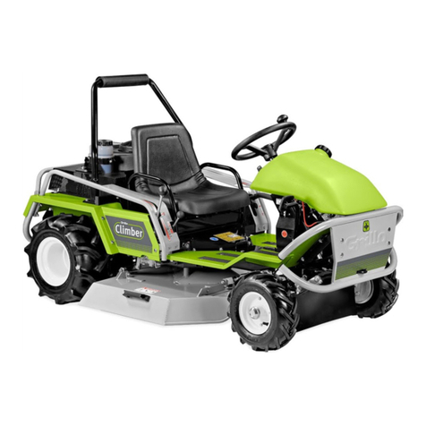
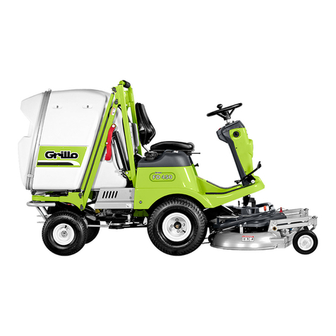
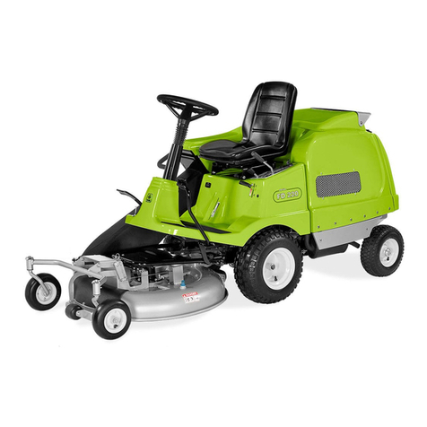
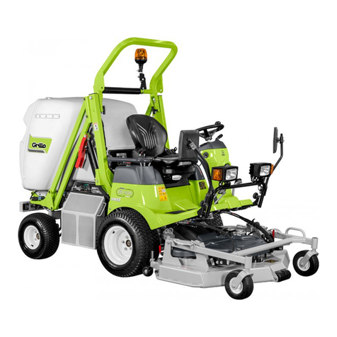
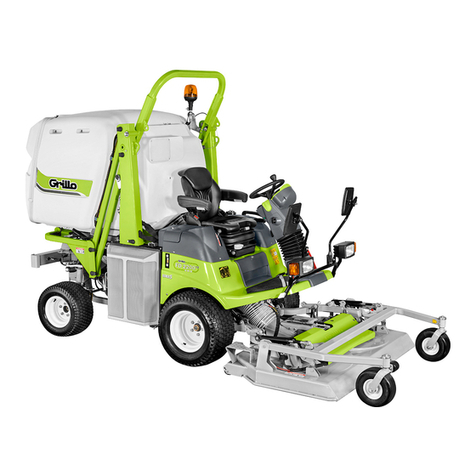
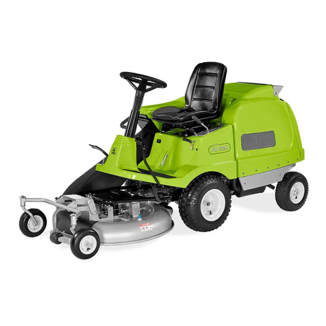
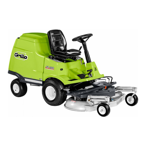
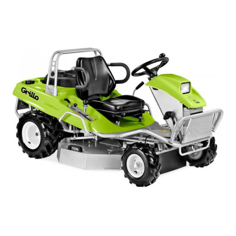
Grillo FD 500 User manual

FD500
02574.2021.05
HydrostaticLawnmower
OPERATOR’S MANUAL EN

2
SUMMARY
1 Introduction...........................................................
2 Description and intended use..............................
3 Safety decals.........................................................
4 General safety regulations...................................
5 General Cautions to bear in mind.......................
6 ...
I......
7 ..
8 .........
9 ......
10 .......................................
11 Instructions for use..............................................
11.1 Checks to be carried out before starting................
11.2 Starting the engine.................................................
11.3 Starting the machine..............................................
11.4 Finishing work........................................................
11.5 Ordinary machine cleaning....................................
11.6 Useful rules for correct use....................................
11.7 Sloping terrain and differential...............................
12 Ordinary adjustments..........................................
12.1 Seat adjustment.....................................................
12.2 Cutting height adjustment.......................................
13 Safety devices.......................................................
13.1 Electronic safeties...................................................
13.2 Parking brake..........................................................
13.3 Roll-Bar...................................................................
14 Extraordinary adjustments..................................
14.1 Adjusting the parking brake.....................................
14.2 Adjustment of the cutting deck................................
14.3 Adjustment of PTO belts.........................................
14.4 Adjusting the grass-catcher alignment....................
14.5 Adjusting the grass-catcher closing hook................
15 Ordinary maintenance and lubrication................
15.2 Engine maintenance...............................................
15.3 Maintenance of the battery......................................
15.4 Maintenance of the cutting deck.............................
16 Extraordinary maintenance..................................
16.1Maintenance of the fuel system...............................
16.2Maintenance of the cooling system.........................
16.3Maintenance of the hydraulic system............................
16.4Maintenance and complete disassembly of the cutting deck
16.5Maintenance of belts...............................................
16.6Maintenance of electrical installation.......................
16.7Replacing the battery..............................................
17 .........................................
18 Maintenance summary table.................................
19 ...................................................
20 Storage and long idle periods..............................
21 .............
22 ...............................
22.1 Assistance...............................................................
22.3 Spare parts..............................................................
22.4 Warranty..................................................................
22.5 How to order spare parts........................................
23 Transport warnings...............................................
24 Disposal.................................................................
EC Declaration of Conformity........................................
FD 500 Hydrostatic Lawnmower / translation of the original instructions
3
3
4
5
7
8
9
10
11
12
13
13
13
13
14
14
14
15
16
16
16
16
16
16
16
17
18
18
18
18
19
19
19
19
20
21
21
22
22
22
22
23
24
25
26
27
29
29
29
30
30
30
30
30
30
30
30
30
31

3
1 INTRODUCTION
Dear Customer,
we thank you for the trust you have placed in our Grillo FD 500 and we
-
quirements. To use and maintain the mower over time, please read and
carefully observe the instructions herewith contained; this will enable
you to get the best results out of your purchase.
Please ensure this manual is kept with the machine.
Reading the operator’s manual is very important.
2 DESCRIPTION AND INTENDED USE
The Grillo FD 500 is a ride-on lawnmower designed the cutting of grass
and for the collection of both grass and leaves.
Any other use is considered to be non-intended.
Before operating the mower, ensure people are familiar with its controls
-
vention.
Any improper use of the machine will invalidate the warranty and relieve
the manufacturer of any liability. Any risk arising from improper use will
be borne by the user.
alteration or tampering invalidates the warranty and relieves the manu-
facturer from any liability in case of damage or accident.
HIGHLIGHTS IN THE MANUAL
This manual contains bold messages highlighted using the symbols be-
low:
CAUTION
information and procedures.
IMPORTANT
Read these messages carefully to avoid injury or damage to the ma-
chine.
The retailer is responsible for inspecting the machine before delivery and
for completing the inspection sheet. “PER-DELIVERY INSPECTION”.
On this occasion the dealer will provide the customer with all the informa-
tion necessary to use the machine.
The customer will receive the machine in optimum condition.

4
Decal - Danger of moving parts.
Decal - Dangers and warnings
Decal - Danger of sharp blades
and Danger of objects thrown
by the rotation of blades
Decal - Danger of moving parts.
Risk
of explosion
Fire hazard
Risk
gas inhalation
Danger
of rollover
Danger
consult the
manual
Danger
of burns
Danger
transmission
parts
Decal - Danger of sharp blades
and Danger of objects thrown
by the rotation of blades
RIGHT AND LEFT SIDE refer to the sides of the machine with the operator sitting on the driver’s seat.
3
WARNING DECALS
FD500 Hydrostatic Lawnmower
RIGHT SIDE LEFT SIDE
Decal - Danger
transmission organs
Decal - Danger
cardan joint

5
Do not touch the cardan shaft while it is rotating, this can cause seri-
ous personal injury. Do not carry out maintenance while the engine is
running.
DANGER of accidents caused by transmission parts
When the engine is running, never touch pulleys or belts, do not carry
out maintenance and keep hands away from the designated area.
Do not use the mower on slippery or sloping ground
greater than 18° (32%).
RISK of explosion.
A burst which separates the tyre from the rim parts can cause serious
injury or death. Make sure to maintain tyre pressures at the levels
recommended in this manual, excessive pressure may cause the
tyre to explode. If a tyre is damaged or cut, do not use it as it may
explode; refer to an expert mechanic for replacement or repair
DANGER of burns
Take particular care not to come into contact with hot engine parts.
4
GENERAL SAFETY RULES
SAFETY RULES
On the machine and in this manual there are warnings and indications
along with this symbol:
it indicates the presence of a potential hazard, so particular attention
should be paid for operator safety and the safety of others who may be
within the operating range of the machine.
This machine is manufactured in compliance with European standards
and is CE marked.
All accident prevention regulations in this manual are important and
must be observed. Always keep the manual at hand and read it
carefully to learn how to use the machine safely. Do not allow any-
one to use the machine without having received full instructions.
EXPLANATION OF WARNING DECALS
Do not put your hands or feet under or into the mower when the engine
is running. Do not work with the mower on gravel or foreign bodies which
can be sucked up and thrown away by the blades, making them very
dangerous.
Keep people at least 15 m away when the machine is running.
DANGER of moving parts
The grass-catcher can be raised and tilted.
Keep a safe distance from the operating machine.

6
SAFETY LOCKINGS
CAUTION:
In addition, always wear seat belts.
Exhaust fumes may cause serious damage to health or death.
If you need to start the engine in a closed area, use an extension
to the exhaust pipe to blow out the smoke.
If it is necessary to operate the engine in a closed area use an extension
piece to the exhaust pipe to blow out the smoke. Work in a well ventilated
area.
FIRE HAZARD
RISK of explosion.
exhale are highly explosive.
DANGER of acid burn
Sulfuric acid in battery electrolyte is poisonous. It is strong enough to
burn skin, eat holes in clothing and cause blindness if it gets in contact
with the eyes
Safety devices
Before using the machine, it is mandatory to put on the individual safety
devices: body protection, protection gloves, safety footwear, ear protection,
goggles.

7
5
GENERAL WARNINGS
ATTENTION: read carefully before operating the machine.
Read this manual completely before starting and running the mower.
Before handing over the machine to other people, they must be
made aware of the safety regulations and how to use the machine.
Pay particular attention to the safety decals on the mower.
Before starting work, always wear appropriate work clothes, long
trousers, gloves, boots, goggles.
Wear acoustic protection systems during continuous use of the ma-
chine. Use ear plugs and ear muffs that comply with current regula-
tions.
HOW TO WORK SAFELY
Before switching on the machine, check that there are no animals
or people in the area around it, especially children, the minimum
distance is 15 m;
Before engaging reverse gear, make sure that there are no people
or obstacles behind the machine.
Check the ground before mowing to ensure there are no stones,
sticks or foreign bodies that become a danger when projected.
Be very careful when working with the mower on areas with sandy
grounds or gravel. Sand and gravel can be sucked up and thrown
away by the blade, making it very dangerous.
Be careful when working near a road.
Do not operate the mower near ditches or verges which may col-
lapse under the weight of the machine, especially if the surface is
uneven or wet.
If you have children, hide the ignition key after using the machine.
Do not allow passengers to ride on the machine.
Children under 16 years of age must not use the machine.
Do not use the machine when fatigued or after drinking alcohol.
Be careful while driving and avoid abrupt steering, especially at high
speed.
Drive at low speed on uneven ground.
On slopes and descents, slow down and always steer slowly.
Lift and empty the grass-catcher only when the machine is station-
ary and on even ground.
Do not leave the machine on a slope.
Before getting off the mower, switch off the PTO, lower the mower
deck if raised, switch off the engine, engage the parking brake and
remove the ignition key.
FURTHER SAFETY ADVICE
When the machine hits a foreign body, disengage the blade, stop the
engine, remove the starter key and inspect the cutting device for dam-
age. If it is damaged, have it repaired before operating the mower again.
If the machine begins to vibrate abnormally after a collision, immediately
carry out a general check to identify the reason for the abnormality. If
necessary, request the assistance of an authorised Grillo workshop.
Rotation of the mower blade is very dangerous, never put your hands or
feet under the mower deck.
Always engage the red safety hooks on the hydraulic cylinder jacks be-
fore servicing the machine with the cylinder raised.
Before checking, adjusting, repairing or simply cleaning the mower, dis-
engage the deck drive and switch off the engine:
Do not place any weights on the seat, this may disable the starter safe-
ty device.
Do not lift the grass-catcher while the machine is moving.
Do not tamper with or disable the safety devices.
Do not change the engine settings, especially the maximum revolutions.
Do not let anyone check the machine while you are sitting on the driver’s
seat with the engine running.
Do not move the machine without the mower deck, the machine may
become unbalanced and driving may be dangerous.
FUEL AND FIRE HAZARD
Only refuel outdoors, always switch off the engine, stay away from
container caps.
machine before starting the engine.
If you have to empty the fuel tank, do this outdoors or in a ventilated
area.
-
clean and free from grass, leaves and dust.
Do not store the machine in buildings where fuel gases could lead
Let the engine cool down before storing the machine in closed rooms.
HOW TO REPLACE COMPONENTS SAFELY
Deformed or damaged blades must always be replaced, never re-
paired.
-
place them with compatible ones, use original belts.
Always use original Grillo spare parts and accessories.
8
Decal - Adjustments
grass-catcher-full microswitch Decal - Lubrication points scheme
Decal - Forward
and reverse gear
Decal - By-pass
hydrostatic pump
Decal - Operating levers
Decal - Engine relays
Decal - Serial number
000000
RIGHT SIDE refers to the side of the machine with the operator sitting on the driver’s seat.
6 IDENTIFICATION OF USAGE DECALS
FD500 Hydrostatic Lawnmower

9
LEFT SIDE refers to the side of the machine for the operator sitting on the driver’s seat.
6 IDENTIFICATION OF USAGE DECALS
Decal - Lubrication points
scheme
Decal - throttle
Decal - Differential lock
Decal - Noise level
Decal – Full grass-catcher
warning buzzer
Decal - Tilt footplate
Decal - Parking brake
Decal - Fuses
Decal - Fan relay
FD500 Hydrostatic Lawnmower

10
23
1. FUEL TANK CAP
2. FULL GRASS-CATCHER WARNING BUZZER BUTTON
3. FUEL LEVEL INDICATOR
4. THROTTLE LEVER
5. PARKING BRAKE LEVER
6. SEAT ADJUSTMENT LEVER
7. DIFFERENTIAL LOCK PEDAL
8. HOUR METRE
9. CUTTING HEIGHT ADJUSTMENT BUTTON
10. RECHARGE BATTERY WARNING LIGHT
11. ENGINE OIL WARNING LIGHT
12. ENGINE HEAT WARNING LIGHT
13. ENGINE TEMPERATURE WARNING LIGHT
1
34
7
9
11 12
14
17
18
8
13
19 20
5
6
15 16
21
22
2
10
7 IDENTIFICATION OF MACHINE CONTROLS AND FUNCTIONS
14. PTO BUTTON
15. STEERING WHEEL
16. IGNITION KEY
17. FORWARD PEDAL
18. REVERSE GEAR PEDAL
19. MOWER DECK LIFTING LEVER
20. GRASS-CATCHER LIFTING LEVER
21. GRASS-CATCHER TIPPING LEVER
22. COOLING LIQUID TANK CAP
23. HYDRAULIC OIL TANK CAP
FD500 Hydrostatic Lawnmower

11
1. PIN WITH COTTER PIN - FRONT MOWER DECK CONNECTION
2. PIVOT WITH PIN - REAR CONNECTION OF THE MOWER DECK
3. LOAD CHUTE
4. CARDAN SHAFT
5. LOCKING HOOK FOR FULL LIFT
6. CUTTING HEIGHT INDICATOR
7. WASHING HOSE CONNECTION NOZZLE
8. TRANSMISSION PROTECTION COVER
9. RIGHT-HAND BLADE PULLEY
10. REAR DECK HEIGHT ADJUSTMENT ROD
11. BELT
12. FRONT BLADE PULLEY
13. BELT TENSIONER PULLEY
14. BELT TENSIONER SPRING
15. FRONT PLATE HEIGHT ADJUSTMENT SCREW
16. ELECTRIC CUTTING HEIGHT DAMPER
17. LEFT BLADE PULLEY
1
2
34
7
5
6
2
1
8
9 17
10
11
12 13 14
10
15
16
TRANSMISSION INNER COMPONENTS
8 MOWER DECK COMPONENTS
FD500 Hydrostatic Lawnmower

12
REAR VIEW WITH OPEN GRASS-CATCHER
1. GRASS-CATCHER DOOR
2. FIXED GRID
3. LIFTING ROD
4. REMOVABLE GRID
5. DEFLECTOR
6. FULL GRASS-CATCHER MICROSWITCH
7. LOAD CHUTE
8. LOCK HOOK
9. ELECTRIC MOTOR
10. SHOCK ABSORBER
10
1
2
3
4
56
7
8
9
9
FD500 Hydrostatic Lawnmower

13
10 TECHNICAL SPECIFICATIONS
ENGINE: KUBOTA D722-E4B-EU-Y2, Diesel EPA /CARB Tier 4, EU
Stage V, ECE R 120, 722 cc, 13,2 kW (17,7HP) at 3200 rpm, 3 cylinders,
liquid cooled, with electric fan and automatic radiator cleaning device.
FUEL TANK CAPACITY: 22 litres.
HYDRAULIC OIL CIRCUIT CAPACITY: 6.7 litres.
STARTER: electric 12 V
DRIVE: Hydrostatic 2-wheel drive with cascade reduction gear, parking
brake and differential.
DIFFERENTIAL LOCK: mechanical with foot control.
DRIVE SYSTEM: steering wheel with hydraulic drive, with pedal-operat-
ed forward and reverse gears.
PTO: electromagnetic, with integrated blade brake.
SPEED: 0 -13 km/h with continuously variable.
WHEELS: front 20 x 10.50-8 GARDEN; rear 16 x 6.50-8 GARDEN.
SEAT: sprung and adjustable, seat belt included.
STEERING WHEEL: mounted on steering column, with knob.
TURNING RADIUS: 32 cm
AUTOMATIC FEATURES: blade disengagement when the grass catch-
er is full, radiator cleaning, electric grass distribution inside the grass
catcher, grass catcher door opening.
parking brake, disc brake on gearbox.
GRASS CATCHER: -
and unloading system with automatic opening.
DISCHARGE HEIGHT: 190 cm
TIPPING HEIGHT: 15 cm
MOWER DECK: 3 blades, with central collection.
CUTTING HEIGHT: from 2.5 to 9 cm continuously variable and electric
adjustment from the driver’s seat.
CUTTING WIDTH: 113 cm.
HOURLY MOWING CAPACITY: 7500 m²/h.
ATTACHMENTS: cutting deck with collection 113 cm, mulching kit.
Length: 271 cm - Width: 119 cm - Height: 151 cm (roll-
bar lowered) - 193 cm (roll-bar raised)
GROUND CLEARANCE: 12 cm
110 cm
530 kg
630 kg
11 INSTRUCTIONS FOR USE
11.1
Check that;
that the engine oil is up to the level;
that the hydraulic oil is up to the level;
3).
grid and push on the lock lever;
that the mower deck and the load chute are clean and correctly
For detailed level controls, please refer to chapter ORDINARY MAINTE-
NANCE and LUBRICATION.
A
B
NEUTRAL FW RW
11.2
1. Insert the key into the ignition block (Fig. 6).
2. Turning the key by one position supplies the electrical circuit with
power: the electronic control unit performs a safety and function
check, the engine glow plugs are preheated and the worklight is
switched on.

14
3. Turning the key one further position supplies power to the machine,
but switches off the worklight.
4. Turning the key to the last position turns the engine on.
5. Release the key after starting.
)
11.3
1. Adjust the seat and carry out the above described necessary
checks.
2. Start the engine.
3. Release the parking brake by removing the lever from the housing
(Fig. 12) and by bringing it to the lowest position.
4. Adjust the cutting height by pushing button (Fig. 8/C).
5. Move the throttle to the half-way position (Fig. 9).
6. Push the PTO button (Fig. 8/D).
7. Always check the running of the PTO safety devices before you
start working,
the PTO is automatically disengaged by getting up from the
seat;
blades stop in less than 5 seconds
8. Press the pedal (Fig. 2/A, Fig. 3/FW) smoothly and start working.
engagement.
9. To stop, simply release the forward pedal which will return to the
10. When the grass-catcher is full, a sensor automatically disengages
blade rotation, thus preventing the clogging of the load chute; alter-
natively, there is a full grass-catcher warning buzzer button on the
re-engaging the PTO, you can keep the blades on when the grass
catcher is full and continue mowing, if small areas are missing to
11. To discharge the grass: raise the grass catcher by operating the
central lever on the hydraulic distributor (Fig. 11/F) and tilt the
grass catcher by using lever Fig. 11/G.
CD
F
G
E
11.4
Once mowing has been completed, disengage the blades and empty
the grass-catcher . Then proceed as follows
1. Release the forward pedal to stop,
2. Set the throttle lever to minimum speed
3. if the mower deck was raised, lower it to the ground,
4. switch the engine off by turning the key to the STOP position and
5.
11.5
CAUTION:

15
Check the ground before mowing: no stones, twigs, roots or foreign
bodies.
When mowing, keep the engine at full speed and adjust the forward
speed according to the grass height. Be careful and slow down
when coming across tall or dense grass.
Check that the blades are not worn, the cutting edge is sharp and
the blade is not damaged. Sharpen the mower blades frequently;
the cut will be better and the engine will run at lower consumption
( ref.16.4 SHARPENING THE BLADES).
IMPORTANT
Keep the grid in front of the radiator clean (Fig. 1).
To remove it, open the grass-catcher door and release the locking
lever (Fig. 4).
If the grass is wet or very high, do not cut with the mower deck in
the lowest position, but set it to an intermediate position.
Check the PTO driving belt tension
Under normal cutting conditions, the microswitch of the full grass-
catcher should be adjusted to the horizontal position. For optimum
we recommend adjusting it at a downward angle when the grass
is wet or very tall, and at an upward angle when the grass is short
or dry. (Fig. 16)
Check the function of the distributor in the grass-catcher: pressing
the PTO button (Fig. 17) automatically activates the distributor
inside the grass-catcher (Fig. 18).
Check that the blades disengage automatically when the grass-
catcher is full or that the warning buzzer is activated.
(ref. 11.3 MACHINE STARTING, point 10)
At the end of each job, proper cleaning ensures a long service life for the
machine and prevents most common mishaps.
The best way to clean the machine is with compressed air or a blower/
vacuum cleaner.
IMPORTANT:
clean of dust and dried grass residues.
If necessary, use water for the body parts for the mower deck, the load
chute and the grass-catcher; avoid wetting the electrical sensor inside
the cutting height to the minimum, connect the water connection nozzle
(Fig. 14) to the water pipe and let the water run for a few minutes, with
the operator sitting in the driver’s seat
engine running
the advance pedal in NEUTRAL position
the blades engaged.
Once the work is completed, also clean the grass-catcher grid.
After using water, run the gearboxes for a few minutes, including those
of the mower deck to ensure that all components dry.
CAUTION
area and fuel line clean and free from grass, leaves and dust at all
times.
11.6 Useful rules for proper use
The machine can work even under severe conditions without clogging
issues. A few preventive measures must be taken and all devices must
be correctly adjusted.
Before starting work, check that the mower deck and the load chute
are perfectly clean and free of grass and dirt.
Check that the load chute is correctly positioned and hooked up

16
11.7
Steep terrain should be driven in uphill/downhill direction by paying at-
tention when changing direction and ensuring that the wheels uphill do
not encounter any obstacles (stones, branches, roots, etc.) which could
cause the machine to lose control. If the drive wheels tend to slip, use
the hydraulic control to raise the mower deck slightly in order to put more
weight on the drive wheels and thus gain more drive. Evaluate the vari-
ous situations and be careful on damp ground and wet grass as the ma-
chine may slip. When travelling downhill, start at low speed and avoid
driving over dry or cut grass as the wheels may lose grip.
The can be engaged by pushing the pedal on the left
hand side of the steering column (Fig. 19) in the condition of wheel slip,
or to load the mower on vehicles with ramps. Only engage the differential
lock if necessary.
12 ORDINARY ADJUSTMENTS
12.1 Seat adjustment
Before starting to work, we recommended to adjust the seat where you
are most comfortable and have the most manageability over the ma-
chine. To adjust the seat forwards or backwards, move the lever on the
left-hand side of the seat to the side (Fig. 20/A), then move the seat. To
adjust the inclination of the backrest, turn the knob on the right-hand side
at the base of the seat (Fig. 20/B). To fold the seat up, pull the levers on
the back of the backrest (Fig. 21).
A
B
12.2
To adjust the cutting height, push the button (Fig. 22), pressing upwards to
raise and downwards to lower.
IMPORTANT
1
When working on uneven ground, gutters or bumps, we recommend
working with the cutter deck in the highest cutting position in order to
avoid impact from the blades. There are two anti-scalp wheels at the
positions using the drillings in the deck.
For a proper use, set the height of the wheels at the closest position but
not in contact with the ground.
13 SAFETY DEVICES
13.1 Electronic safeties
On the FD 500, an electronic control unit receives inputs from the mi-
croswitches located on the seat, forward pedal, parking brake and
grass-catcher. Based on these inputs, the control unit produces logical
blocks for the safety of the machine and the operator.
In particular, always remember that:
THE ENGINE
turns off if the operator gets up from the seat with the parking brake
off.
will not start if the driver is not seated in the driving seat, unless the
will not start if the drive pedal is not in the NEUTRAL position.
THE PTO
does not activate if the parking brake is engaged
does not activate if the basket is open or full, unless the warning
buzzer switch has been pressed.
does not activate if the engine is overheated.
13.2
The FD 500 is equipped with a hydraulic feed system. Simply release
the foot pedal to brake. To engage the parking brake, pull the lever with
knob (Fig. 25) and position it in the housing. To release the parking
brake, simply remove the lever from the housing and move it to a lower
position. If the parking brake is engaged and the travel pedal is pressed,
the warning buzzer will sound to warn the operator to release the brake.
The blades cannot be engaged in this condition.
With the parking brake engaged, you can leave the driver’s seat with the
engine running.

17
13.3
CAUTION
Roll-over protection is not ensured if the roll-bar is in the lowered
position.
Do not operate the machine on uneven ground or on slopes with the
roll-bar in the lowered position.
Only lower the roll-bar when absolutely necessary.
Do not wear a seat belt when the roll-bar is lowered.
Drive slowly and carefully.
Raise the roll-bar as soon as clearance permits.
Take care when working under the tree crowns. Check that there
are no low branches or other obstacles that could get in the way of
the roll-bar.
1. Park the machine on a level surface.
2. Switch off the PTO, lower the cutting deck and engage the parking
brake.
3. Switch off the engine and fold down the seat, using the levers at
the rear (Fig. 27).
4. Undo the lower screws of the roll cage (Fig. 28).
5. Lower the roll bar behind the seat (Fig. 29) and tighten the screws
in the new position (Fig. 30).
CAUTION:
permits
1. Park the machine on even surface.
2. Switch off the PTO, lower the mower deck and engage the parking
brake.
3. Switch off the engine and fold down the seat, by using the levers
at the rear (Fig. 27).
4. Unscrew the lower screws on the roll bar (Fig. 30).
5. Raise the roll bar (Fig. 26) and secure it by tightening the screws
in the new position (Fig. 28).

18
A
B
C
14.3 Adjustment of PTO belts
To adjust the tension of the PTO belts:
1. Release the radiator, using the lever to access the clutch (Fig. 36).
2.
3.
A
C
B
14 EXTRAORDINARY ADJUSTMENTS
14.1
If the parking brake is ineffective, it is possible to adjust it using the ad-
lock nut and unscrewing or screwing the adjusting screw and nut, it is
possible to modify the tension of the wire connected to the lever. The
effectiveness of the brake is due to the block between the two pads of
activated, it is important to have a clearance between the pad and the
disc (0.4÷0.6 mm) and that the wire is not tensed.
14.2
An optimal alignment of the deck is essential to achieve an evenly mowed
lawn. Place the mower on a smooth, even surface, ensure the distributor
1. check the correct tyre pressure (1.5 bar) check the distance of the
A B
2. in A the measurement must be 15/20 mm, in B it must be about 5/10
mm greater than A.
3. if necessary, proceed as follows:
part;
to adjust the height of the rear part;
height between the left and right-hand sides.

19
14.4
For this reason proceed as follows:
1. Put the grass-catcher in completely closed position and check the
alignment with the load chute.
2. If the seal does not seal well or is too compressed, loosen the
3. Loosen the safety nut at the top of the central hydraulic cylinder rod.
movement of the basket, so that the seal is slightly compressed and
the grass catcher is aligned with the load chute.
AA
B
4. If necessary, the position can also be adjusted by acting on the
catcher away from and upwards from the chute, shortening the
piston rod moves the grass catcher closer to and downwards from
the chute.
IMPORTANT
14.5
The grass-catcher lock hook is adjusted using the dedicated screw (Fig.
41/C).
It is necessary to leave approximately 2 mm clearance between the hook
41/D) it is possible to adjust the automatic opening angle of the tailgate.
D
2 mm
C
15
CAUTION:
devices or lifted up, in places accessible to inexperienced peo
environment!
CAUTION
15.1
GREASE LUBRICATION POINTS
Consult the location of the lubrication points according to the schemes
on the machine.

20
lubricate where there (1 to 7), is a single grease nipple. The components
are following:
1. right-hand deck arm
2. right swivel wheel
3. right-hand blade hub
4. front blade hub
5. platter drive sleeve
6. left caster wheel
7. left-hand deck arm
-
chine body (1 to 13), followed by the number of existent grease nipples.
The components are as follows:
1. forward/reverse gear, grease nipple under the footboard
2. mower deck lifting pistons, left/right hand
3. cardan joint: both spiders
4. footplate: left/right coupling
5. front wheel hub bearings, left/right hand
6. PTO gearbox
7. hydraulic pump transmission pulley
8. rear axle: centre pin and spindles right/left hand
9. lower lift arms: bottom pins, right/left hand
10. grass-catcher: left/right hinges and centre tilt piston
11. upper lift arm: lower right/left-hand hand pins
12. grass-catcher lifting pistons, right/left hand
13. upper lift arm: upper pins, right/left hand
14. lower lift arm: upper pins, right/left hand
IMPORTANT
15.2 Engine maintenance
IMPORTANT:
HOW TO MANUALLY ACCESS THE ENGINE COMPARTMENT
To access the engine if the machine breaks down, engage the parking
brake, switch off the engine, hold down the grass-catcher folding lever
and simultaneously push the grass-catcher towards the rear of the ma-
chine.
The grass-catcher will rotate allowing you to access the engine compart-
ment.
AIR FILTER
every 8 hours. For maintenance intervals and procedures refer to the
rules contained in this manual (CHAPTER 18 MAINTENANCE SUM-
MARY TABLE); for further details consult the engine manual. If you work
every 4 hours or when necessary. There is also a safety cartridge inside
Only replace the safety cartridge if it is damaged or worn.
A
2 safety cartridge
5 closing hook
6 cap
7 dust ejection valve
ENGINE OIL
For lubrication intervals and lubrication methods follow the rules
contained in this manual (CHAPTER 18 MAINTENANCE SUMMARY
TABLE); for further details refer to the engine manual.
IMPORTANT:
Then change the oil every 75 hours. For the engine, use SAE 15W40 oil
cold. To remove all the oil from the engine, unscrew the screw located
Table of contents
Other Grillo Lawn Mower manuals

Grillo
Grillo GF1 User guide

Grillo
Grillo FD 2200 STAGE 5 User manual

Grillo
Grillo CLIMBER 8.22 User manual

Grillo
Grillo MD22 N User manual

Grillo
Grillo FD450 User manual

Grillo
Grillo MD 22 User manual

Grillo
Grillo MD 22 User manual

Grillo
Grillo CLIMBER 10 User manual

Grillo
Grillo FD 280 User manual

Grillo
Grillo FD900 4WD User manual

Grillo
Grillo FD450 User manual

Grillo
Grillo FD 220 R User guide

Grillo
Grillo FD 1100 4WD User manual

Grillo
Grillo MD15 User manual

Grillo
Grillo CL62 User manual

Grillo
Grillo FD 2200 4WD User manual

Grillo
Grillo FD 220 R User manual

Grillo
Grillo CLIMBER 8.22 User manual

Grillo
Grillo fm2200 User manual

Grillo
Grillo CL 620 User guide