Grillo FD 2200 TS stage V User manual

FD 2200 TS stage V
OPERATOR’S MANUAL
MANUALE DELL’OPERATORE
MANUEL D’UTILISATION
BEDIENUNGSANLEITUNG
MANUAL DE INSTRUCCIONES
02547 - 19


SUMMARY
Safety rules
Instructions
Warnings 5
Identification and servicing 6
Technical specifications 7
Putting the machine into service 8
Instructions for use 8
Maintenance and lubrication 0
Implements 20
Pictures 75
EC Declaration of conformity
INDICE
Norme antinfortunistiche
Istruzioni
Avvertenze 2
Identificazione e assistenza 22
Caratteristiche tecniche 23
Messa in opera della macchina 24
Istruzioni d’uso 25
Manutenzione e lubrificazione 27
Accessori 38
Figure 75
Certificato di conformità CE
INDEX
Règles de sécurité
Instructions
Mises en garde 39
Identification et assistance 40
Caractéristiques techniques 4
Mise en service de la machine 42
Mode d’emploi 42
Maintenance et lubrification 44
Accessoires 54
Illustrations 75
Certificat de conformité CE
VERZEICHNIS
Sicherheitsvorschriften
Anleitung
Sicherheitsrelevante Hinweise 56
Identifikation der Maschine und Kundendienst 57
Technische Daten 58
Inbetriebnahme der Maschine 59
Betriebsanleitung 59
Wartung und Schmierung 6
Zubehör 73
Abbildungen 75
EG-Konformitätserklärung
I

SAFETY RULES
This symbol alongside messages and instructions in this manual and on the machine indicates a potential danger;
care must be taken so ensure your own safety and that of anyone within the machine’s range of operation.
BEWARE! This machine has been manufactured to European standards and carries the mark.
NORME ANTINFORTUNISTICHE
Sulla macchina ed all’interno di questo manuale sono presenti scritte ed indicazioni accompagnate da questo
segnale, stanno ad indicare la presenza di un potenziale pericolo per cui opportuno utilizzare una particolare
prudenza per la propria sicurezza e di quanti si possono trovare nel raggio di azione della macchina.
ATTENZIONE! Questa macchina costruita secondo le normative europee ed certificata col marchio .
RÈGLES DE SÉCURITÉ GÉNERALE
Sur la machine et sur les pages de ce manuel se trouvent des mises en garde et des indications accompagnées de
ce signal; elles indiquent la présence d’un danger potentiel qui explique la nécessité d’être particuli rement prudent
pour sauvegarder sa propre sécurité et la sécurité de tous ceux qui peuvent se trouver dans le rayon d’action de la
machine.
ATTENTION! Cette machine est fabriquée selon les directives européennes et est certifiée par le label
SICHERHEITSVORSCHRIFTEN
Auf der Maschine und in diesem Handbuch finden Sie Beschriftungen und Hinweise mit dem hier abgebildeten
Symbol. Sie weisen auf eine potentielle Gefahr hin, und Sie sollten besonders gefahrenbewusst vorgehen, um
unnötige Risiken für sich selbst und andere Personen, die sich im Aktionsbereich der Maschine befinden,
auszuschließen.
ACHTUNG! Diese Maschine entspricht den europäischen Richtlinien und ist mit dem Zeichen zertifiziert.
NORMAS DE SEGURIDAD
En la máquina y dentro de este manual hay leyendas e indicaciones acompañadas por esta señal que indican la
presencia de un peligro potencial o la necesidad de adoptar una prudencia mayor para la seguridad propria y de
los que se encuentran en el radio de acción de la máquina.
¡ATENCIÓN! Esta máquina es fabricada según las normas europeas y es certificada con la marca .
NORMAS DE PRECAUÇAÕ CONTRA ACIDENTES
Na máquina e neste manual, estão presentes escritas e indicações acompanhadas por este sinal. Estas chamam
a atenção do Operador para a presença de um risco potencial. Portanto, recomenda-se a máxima atenção para
garantir a própria segurança e a de terceiros, que possam estar no raio de ação da máquina.
ATENÇÃO! Esta máquina foi construída em conformidade com as normas europeias e está certificada com a marca .
GENERAL SECURITY RULES
NORME DI CARATTERE GENERALE SULLA SICUREZZA
SICHERHEITSHINWEISE
RÈGLES GÉNÉRALES DE SÉCURITÉ
NORMAS DE CAR CTER GENERAL SOBRE LA SEGURIDAD
NORMAS DE CAR CTER GENERAL ACERCA DA SEGURANÇA
Pay attention to symbol DANGER! It points out all m
ost dangerous operations according to the situation. All safety rules are important and therefore must be strictly observed. Always keep this handbook within the
reach, read it carefully and learn how to use the equipment in a safe way. Let nobody, unprovided with necessary information, work with the equipment.
Fare attenzione al simbolo PERICOLO! Esso indica la presenza delle principali situazioni di pericolo. Tutte le norme antinfortunistiche contente sono importanti e
vanno rispettate. Tenere sempre questo manuale a portata di mano, leggerlo attentamente ed imparar ad usare l’attrezzatura in modo sicuro. Non permettere che
qualcuno operi con questa attrezzatura senza aver ricevuto istruzioni esaurienti.
Attention au symbole DANGER! Il indique la présence des principales situations de danger. Toutes les normes contenues pour la prévention des accidents sont
importantes et doivent être respectées scrupuleusement. Garder toujours ce manuel à la portée de la main, le lire attentivement et apprendre à utiliser ce matériel en
toute sécurité. Ne pas permettre que d’autres personnes utilisent ce matériel sans avoir reçus des instructions exhaustives.
Achtung - die mit dem Symbol GEFAHR! gekennzeichneten Hinweise weisen auf potentielle Gefahrensituationen hin. Alle sicherheitsrelevanten Hinweise in diesem
Handbuch sind sehr wichtig und müssen unbedingt befolgt werden. Bewahren Sie dieses Handbuch stets griffbereit auf, lesen Sie es aufmerksam durch, und lernen
Sie, die Maschine und die gesamte Ausrüstung sicher zu benutzen. Die Maschine darf nur von Personen benutzt werden, die vorher entsprechend unterwiesen
wurden.
Preste atención al símbolo ¡PELIGRO! Indica la presencia de situaciones importantes de peligro. Todas las normas de prevención de accidentes detalladas son
importantes y deben respetarse strictamente. Conserve este manual al alcance de la mano, léalo atentamente y aprenda a utilizar el equipamiento de modo seguro.
No permita que otras personas operen con este equipamiento sin haber recibido instrucciones exhaustivas.

Take special care not to touch hot parts of the engine.
Prestate particolare attenzione a non entrare in contatto con parti surriscaldate del motore.
Veiller tout particuli rement à ne pas toucher des éléments surchauffés du moteur.
Achtung – keine heißen Motorteile berühren!
No tocar partes recalentadas del motor.
Tome muito cuidado para não entrar em contacto com as partes aquecidas do motor.
Engine exhaust fumes can cause sickness or death. If it is necessary to run an engine in an enclosed area,
use an exhaust pipe extension to remove the fumes. Always try to work in a well ventilated area.
I gas di scarico possono causare malanni o morte. Se necessario mettere in moto un motore in uno
spazio chiuso, usare una prolunga tubo di scarico per far uscire il fumo. Lavorare in una zona ben
ventilata.
L’exhalation des gaz d’échappement peut être cause d’intoxication ou de mort. S’il est vraiment nécessaire
d’allumer le moteur à l’interieur, appliquer au tuyau d’échappement un autre tuyau extensible pour
permettre la sortie des gaz. Il est toujours mieux de travailler en plein air.
Auspuffgase können Übelkeit oder Tod verursachen. Wenn es notwendig ist, einen Motor in einem
geschlossenen Raum laufen zu lassen, benützen Sie eine Verlängerung, um das Auspuffgas abzuleiten.
Versuchen Sie immer in einem gut belüfteten Raum zu arbeiten.
Los gases de escape pueden provocar enfermedades o muerte. De tener que poner en marcha un motor
en un espacio cerrado, usar una prolongación del tubo de escape para que salga el humo. Trabajar en
una zona bien ventilada.
Os gases de escape podem causar danos ou morte. Caso seja ncessário fazer com que o motor funcione
num espaço fechado, utilize uma extensão para o tubo de escape que os fumos sejam espulso para o
exterior. Trabalhe numa área bem ventilada.
Caution! Never touch moving pulleys or belts. They can be very dangerous. Never do maintenance with
engine running.
Attenzione! Non toccare mai pulegge o cinghie in movimento, creano gravi danni alla persona. Non fare
manutenzione col motore in moto.
Attention! Ne jamais toucher ni poulies ni courroies en mouvement, elles peuvent provoquer des accidents
aux personnes. Ne pas faire l’entretien quand le moteur est en marche.
Vorsicht! Nie laufende Riemenscheiben oder Treibriemen anfassen, da es gefährlich ist. Nie bei laufendem
Motor Instandhaltung machen.
¡Atención! No tocar jamás poleas o correas en movimiento, porque pueden crear graves daños a la
persona. No efectuar el mantenimiento con el motor en marcha.
Atenção! Nunca toque nas polias ou correias em movimento devido ao alto risco de ferimentos. Nunca
faça a manutenção da máquina com o motor ligado.
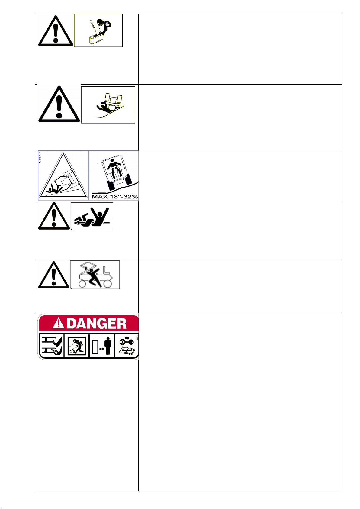
A burst which separates the tyre from the rim parts can cause serious injury or death.
La separazione fra pneumatico e cerchione, causata dall’esplosione del pneumatico, può provocare serie
ferite o addirittura la morte.
La séparation entre le pneu et la jante, provoquée par l’explosion d’une roue peut causer des dommages,
blessures ou la mort.
Die Trennung der Räder von den Felgen durch Explosion kann schwere Verletzungen oder den Tod
verursachen.
La separación entre el neumático y la llanta producida por la explosión del neumático puede provocar
graves herida e incluso la muerte.
A separação entre o pneumático e o aro, provocada pela explosão do pneumático, pode causar graves
ferimentos ou até mesmo a morte.
Prevent battery explosions: keep sparks, lighted matches and open flames away from the top of the
battery. Battery gas can explode.
Per prevenire l’esplosione della batteria, tenete scintille, fiammiferi accesi e fiamme lontani dalla stessa. Il
gas della batteria può esplodere.
Prevenir l’explosion de la batterie: tenir les éticelles, les alumettes et le feu loin de la batterie. Le gaz de la
batterie peut exploser.
Vorbeugung der Batterie-Explosion. Entfernen Sie Funken, Zündhölzer und Flammen von der Batterie.
Das Batteriegas kann explodieren.
Para prevenir la explosión de la batería, mantener chispas, cerillas encendidas y llamas lejos de la misma.
El gas de la batería puede explotar.
Para prevenir explosao da bateria ter centelhas, fosforos acendido e chamas longe da mesma.O gas da
bateria poderia expludir.
Handle fuel with care, it is highly flammable: Do not refuel machine while smoking, when machine is near
an open flame or sparks, or when the engine is running. Stop the engine.
Maneggiare il carburante con cura, altamente infiammabile; non fate rifornimento mentre fumate, o vicino
a fiamme o scintille, o quando il motore acceso.
Manier avec soin le carburant car c’est tr s inflammable. Ne pas remplir le réservoir si vous êtes en train
de fumer ou pendant que la machine est pr s du feu ou d’étincelles ou encore pendant que la machine
travaille. Arrêter le moteur.
Treibstoff vorsichtig handhaben, da er sehr entzündbar ist: beim Tanken nicht rauchen. Nicht tanken,
wenn die Maschine in der Nähe von Flammen oder Funken ist oder wenn der Motor läuft. Immer den Motor
abschalten.
Manejar el combustible con cuidado porque es sumamente inflamable; no repostar mientras se fuma o
cerca de llamas o chispas, o cuando el motor está encendido.
Manuseie o carburante com cuidado, pois este altamente inflamável; não fume durante o abastecimento
da máquina ou enquanto o motor estiver ligado, não o aproximado de chiama ou de faíscas.
Rotating blades are dangerous. Protect children and prevent accidents.
Le lame in movimento sono pericolose. Proteggete i bambini e prevenite gli incidenti.
Les lames en rotation sont dangereuses. Proteger les enfants et prévenir les accidents.
Arbeitende Messer sind gefährlich, Kinder schützen und Unfälle vorbeugen.
Las cuchillas en movimiento son peligrosas, proteger a los niños y prevenir los accidentes.
As facas em movimento sao perigosas.Proteger as criancas e prevenir acidentes.

Sulfuric acid in battery electrolyte is poisonous. It is strong enough to burn skin, eat holes in clothing and
cause blindness if it gets in contact with the eyes.
L’acido solforico della batteria velenoso. È in grado di causare bruciature alla pelle, bucare vestiti e
causare cecità se arriva negli occhi.
L’acide sulfurique de la batterie est toxique. Il peut causer des brûlures à la peau, endommager les
vêtements et peut aussi causer cécité.
Säure der Batterie ist giftig. Sie kann die Haut verbrennen, Löcher in die Kleidung machen und Blindheit
verursachen.
El ácido sulfúreo de la batería es venenoso, puede provocar quemaduras en la piel, agujear la ropa y
provocar ceguez si llega a los ojos.
O acido sulfurico e toxico. Pode ser causa de queimadura da pele, furar roupa e provocar cegueira, no
caso chegarem em contacto com os olhos.
Avoid tipping. Do not drive where machine could slip or tip. Stay alert for holes and other hidden objects.
Evitate le scivolate. Non guidate dove la macchina potrebbe scivolare o inclinarsi. Attenzione a buche o ad
oggetti nascosti.
Eviter les pentes. Ne pas conduire la machine où elle peurrait glisser ou se renverser. Faire attention aux
trous ou à tout autre obstacle caché.
Nicht dort fahren, wo die Maschine rutschen könnte. Vorsicht bei Löchern oder versteckten
Gegenständen.
Evitar patinazos. No conducir donde la máquina pueda patinar o inclinarse. Cuidado con los baches o con
objetos escondidos.
Evitar deslizamentos.Nao diriga em lugares onde a maquina poderia deslizar. Ter cuidado a buracos e
objetos escondidos.
DANGER! Machine rollover: Do not use this machine on slopes greater than 18° (32%).
PERICOLO! Ribaltamento della macchina. Non usare questa macchina su pendii superiori ai 18° (32%).
DANGER! Renversement de la machine. Ne pas utiliser cette machine sur des pentes supérieures à 18°
(32%).
GEFAHR! Umstürzen der Maschine. Die Maschine nicht an Hängen mit einer Neigung über 18° (32%)
einsetzen.
¡PELIGRO! Volcado de la máquina. No utilizar esta máquina en pendientes superiores a 18° (32%).
PERIGO! Revirado da máquina. Não use essa máquina em inclinacaoes além de 18° (32%).
Beware! Never touch moving universal joint. It can be very dangerous. Never carry out any maintenance
with the engine running.
Attenzione! Non toccare il giunto cardanico in rotazione, crea gravi danni alla persona. Non fare
manutenzione con il motore in moto.
Attention! Ne jamais toucher le joint de cardan en mouvement, il peut causer des dommages à la
personne. Ne pas faire l’entretien quand le moteur est activé.
Vorsicht! Nie laufendes Kardangelenk anfassen, da es gefährlich ist. Nie bei laufendem Motor
Wartungsarbeiten durchführen.
¡Atención! No tocar jamás junta cardán en movimento, porque puede crear graves daños a la persona.
No efectuar el mantenimiento con el motor en marcha.
DANGER! MOVING PARTS. Do not approach while the engine is running.
PERICOLO! ORGANI IN MOVIMENTO. Non avvicinatevi con il motore in moto.
DANGER! ORGANES EN MOUVEMENT. Ne pas s’approcher lorsque le moteur est activé.
GEFAHR! SICH BEWEGENDE MASCHINENTEILE. Es ist gefährlich, sich der Maschine zu nähern, wenn
der Motor läuft.
¡PELIGRO! ÓRGANOS EN MOVIMIENTO. No acercarse con el motor en marcha.
WARNING! SHARP PARTS. Keep hands and feet away. Do not operate the mower over
gravel or foreign bodies which may be sucked up and ejected by the blades, generating a
danger. Keep people away. Remove the key and read the instruction manual before
attempting to carry out any maintenance or repairs to the machine.
ATTENZIONE! ORGANO TAGLIENTE. Tenere lontano mani e piedi. Non lavorare col
rasaerba sopra alla ghiaia o corpi estranei che possono essere aspirati e centrifugati dalle
lame risultando molto pericolosi, tenere lontano le persone. Togliere la chiave e leggere le
istruzioni prima di effettuare qualsiasi operazione di manutenzione e riparazione.
ATTENTION! ORGANE TRANCHANT. Eloigner les mains et les pieds. Ne pas utiliser la
tondeuse sur le gravier ou sur des corps qui peuvent être aspirés et centrifugés par les
lames et devenir tr s dangereux. Les personnes doivent se trouver à une certaine distance.
Enlever la clé et lire les instructions avant toute operation de maintenance et de réparation.
ACHTUNG! SCHARFE KLINGEN. Hände und Füße fernhalten. Beim Mähen nicht über
Schotter, Steine oder andere Fremdkörper fahren, da diese durch die Drehbewegung der
Messer angesaugt und weggeschleudert werden können (Verletzungsgefahr). Nicht in der
Nähe von anderen Personen mähen. Vor jedem Wartungs- bzw. Reparatureingriff den
Startschlüssel abziehen und die Gebrauchsanleitung durchlesen.
¡PELIGRO! ÓRGANO CORTANTE. Mantener alejados los pies y las manos. No limpiar la
herramienta con el motor en marcha. ¡Peligro! Expulsión de objetos: mantener alejadas a las
personas. Atención: quitar la llave y leer las instrucciones antes de efectuar cualquier
operación de mantenimiento o reparación.
ATENÇÃO! Órgão cortante. Ficar longe com pés e maos. Nao trabalhar com a máquina
sobre cascalho ou objetos que poden ser aspirados e centrifugados gerando perigo, manter-
se longe das pessoas.
Tirar a chave de ignicao e ler as istrucoes antes de efetuar qualquer operacao de reparo ou
servico.

Before using the machine, it is mandatory to put on the appropriate individual safety devices:
body protection, protection gloves, security shoes, ear protection.
Prima di utilizzare la macchina, obbligatorio indossare gli appositi dispositivi di sicurezza
individuali: protezione del corpo, guanti di protezione, calzature di sicurezza, protezione
dell’udito.
Avant d’utiliser la machine, il est obligatoire de mettre les dispositifs individuels de sécurité
appropriés: protection du corps, gants de protection, chaussures de sécurité, protection de
l’ouïe.
Vor dem Gebrauch der Maschine ist es vorgeschrieben, die geeignete persönlichen
Schutzkleidung anzuziehen: Körperschutz, Schutzhandschuhe, Sicherheitsschuhe,
Gehörschutz.
Antes de utilizar la máquina es obligatorio ponerse los dispositivos individuales de seguridad
apropiados: protección del cuerpo, guantes de protección, calzado de seguridad, protección
del oído.
CAUTION! When making the engine maintenance and keeping the grass catcher up,
engage the two red safety lockings on the hydraulic cylinders. Do not work on the engine
without having engaged the lockings. Do not keep the machine stopped with the grass
catcher up without having engaged the two red safety lockings.
ATTENZIONE! Se si esegue la manutenzione del motore tenendo il cesto alzato, inserire i
due blocchi di sicurezza verniciati rossi sui cilindri oleodinamici. Non lavorare sul motore
senza aver inserito i blocchi. Non tenere la macchina in sosta col cesto sollevato senza aver
inserito i due blocchi rossi di sicurezza.
ATTENTION! Si l’entretien du moteur est fait en tenant le bac soulevé, activer les deux
supports de sécurité rouges sur les vérins oléodynamiques. Ne pas travailler sur le moteur
sans avoir fixé ces deux supports. Ne pas garder la machine arrêtée avec le bac soulevé
sans avoir fixé les deux supports rouges de sécurité.
ACHTUNG! Wenn Sie den Motor warten und den Grasbehälter hoch halten, müssen Sie die
beiden roten Sicherheits-Sperren auf den hydraulischen Zylindern eingelegt haben. Wenn
der Grasfangkorb oben ist, darf die Maschine nicht stehen, ohne dass die roten Sicherheits-
Sperren eingelegt sind.
¡ATENCIÓN! Si se realiza el mantenimiento del motor con el cesto alto, es necesario activar
los dos soportes rojos de seguridad de los cilindros oleodinámicos. No trabajar sobre el
motor sin haber fijado los soportes. Cuando la máquina está parada con el cesto levantado,
los dos soportes rojos de seguridad tiene que estar siempre activados.
ROLL BAR
Attention! In dangerous working situations where the machine could roll-over the upper arch
must be always raised as shown in the picture and properly fixed using appropriate screws.
In addition, always wear seat belts. The use of the roll-bar can be avoided only when there is
no risk at all of rolling-over.
ARCO DI PROTEZIONE (roll bar)
Attenzione! In situazioni di pericolo ribaltamento il dispositivo di sicurezza roll bar va
mantenuto alzato e ben avvitato. Usare anche la cintura di sicurezza. Limitare al massimo
l’uso della macchina senza arco di protezione, riservandolo alle situazioni in cui non c’
alcun rischio di ribaltamento.
ARCEAU DE SECURITE
Attention! Dans les situations avec risque de retournement l’arceau de sécurité doit être
maintenu levé et bien fixé. Utiliser aussi la ceinture de sécurité. Limiter autant que possible
l’utilisation de la machine sans arceau de sécurité, en la réservant aux situations qui ne
présentent aucun risque de retournement.
ÜBERROLLBÜGEL
Vorsicht! Die Maschine ist mit einem klappbaren Überrollbügel ausgestattet, der die
Passagiere schützt, soll die Maschine umkippen. Der Überrollbügel muss immer angehoben
werden und mit Schrauben gut befestigt. Ziehen Sie auch immer die Sicherheitsgurte an.
Den Überrollbügel darf nicht benutzt werden, nur wenn keine Gefahr zum Umkippen besteht.
ARCO DE PROTECCIÓN ANTI-VUELCO
¡Atención! En las situaciones de peligro de vuelco, el dispositivo de protección anti-vuelco
tiene que estar levantado y bien fijado. Utilice también el cinturón de seguridad. Evite al
máximo el uso de la máqina sin arco anti-vuelco, limitándolo a las situaciones que no
presentan ningún riesgo de vuelco.

FD2200TS/ Translation of the original instructions
HYDROSTATIC LAWNMOWER
FD 2200TS stage V
Dear Customer,
Thank you for having purchased our FD2200TS stage V. e are confident that this machine will fully satisfy all your
requirements. To use and maintain the mower at its best, we urge you to read and observe carefully the directions
given in this handbook; this will ensure the best possible results and will also safeguard your investment. Please
keep this handbook in a safe place. It should accompany the machine throughout its working life.
GENERAL DESCRIPTION AND INTENDED USE
The Grillo mower FD2200TS stage V is a mower with an operator on board, designed to cut and the collect grass
and leaves. It can be equipped with a 180 cm collection deck and/or a 160 LMP deck (mulch, rear or side
discharge), an all-purpose flail, a pivoting brush, a snow blade and a cab.
ATTENTION! Read ca efully befo e sta ting the engine. The following wa nings a e
impo tant fo ope ato safety!
WARNINGS
Caution is the main safeguard in preventing accidents. e urge you to read the warnings that follow when using the
mower, before starting any work at all. Improper use of the mower and its equipment can be dangerous. To reduce
the risks to the minimum, observe the necessary precautions set out below:
1)Read the whole of this manual before starting and using the mower for the first time.
2)Pay particular attention to the warnings and safety labels set out around the mower.
3)Before allowing others to use the machine, make sure they are aware of the safety precautions and how it is
used.
4)Before starting work, always change into suitable work clothes, gloves, boots and goggles.
5)It is COMPULSORY to wear special acoustic protection (ear defenders) during work.
6)Before starting the machine, make sure there are no people around it; especially children.
7)Before driving the machine in reverse, make sure there are no persons or obstacles in the way.
8)Check the condition of the ground before mowing. Make sure there are no stones, sticks or other objects,
which could be run over and become a danger when projected.
9)If any impact with a foreign object occurs, disengage the blade, turn off the engine, remove the ignition key
and examine the mower; if the machine vibrates have it repaired.
10)Before getting off the mower, turn off the engine, disengage the PTO, remove the ignition key and lower the
cutting deck to its lowest position.
11)Always drive slowly along uneven paths.
12)Keep the speed down when driving down slopes.
13)Always turn slowly when driving downhill.
14)The user is always liable for any damage caused to third parties.
15)Deformed or damaged blades must always be replaced, never just repaired.
16)Always use original Grillo spare parts and accessories.
17)Only work in sunlight or under effective artificial lighting.
18)Only store fuel in suitable containers designed for the purpose.
19)Be very careful when working close to a road.
20)Lift and empty the grass catcher only when the machine is still and on flat ground.
21)Allow the engine to cool down before putting the machine away in a closed environment.
IMPROPER USE TO BE AVOIDED
22)Do not allow passengers to ride on the mower.
23)Do not allow under-age children to operate it; use is prohibited to children under 16.
24)Do not operate the machine when tired or after drinking alcohol.
25) Do not operate the mower near to ditches or verges which could collapse under the weight of the machine,
especially when the surface is loose or wet.
26)Do not stop when working up or down slopes.
27)Do not allow any fuel spillage and after filling the tank wipe away any spilt fuel before starting the engine.
28)Do not tamper with the safety devices or disable them.
29)Do not change the engine settings, especially the maximum number of rpm.
30)Do not rest heavy loads on the seat, the starter safety device could become disengaged.
31)Never attempt any adjustments or cleaning with the engine running.
5

FD2200TS/ Translation of the original instructions
32)Never allow anyone to check the machine while you are seated at the controls with the engine running.
33)Do not move the machine without the deck, wheelies may result and be very dangerous.
34)Do not lift the grass catcher when the machine is moving.
35)Replace worn or damaged exhaust mufflers.
FURTHER SAFETY ADVICE
The above-mentioned warnings could not be enough to avoid all risks, if the operator does not use this mower
correctly. Therefore, for your safety we give the following advice:
36)The mower blade is very dangerous when rotating, never put hands or feet underneath the mower deck.
37)Do not drive in reverse at high speed.
38)It is dangerous to operate the steering wheel abruptly with the engine at full power.
39)Fill the tank with fuel before starting the engine. Only refuel outdoors, always turn off the engine, keep away
from sparks or naked flames, do not smoke! Always replace the cap on the fuel tank and those on fuel
containers properly.
40)Drain the fuel tank outdoors only, if necessary.
41)Do not operate the mower over gravel which could be sucked up and thrown away by the blade, becoming very
dangerous.
42)If you have children, hide the ignition key after using the machine.
43)CAUTION: to avoid the risk of fire, keep the engine compartment, exhaust box, discharge outlets, battery, tank
area and fuel pipes free of grass, leaves, dirt, etc.
44)Do not store the machine inside any building where the engine fumes can reach naked flames, sparks or bare
electrical wires.
Remove the implements and turn off the engine:
a) befo e cleaning obst ucted points.
b) befo e checking o epai ing the mowe .
c) if the machine hits a fo eign object (check the mowe deck to see if it is damaged. Make epai s befo e
you ope ate it again).
d) if abno mal vib ation occu s, stop and inspect the machine. Contact the nea est autho ised se vice
cent e if you need help.
IDENTIFICATION AND SERVICING
IDENTIFICATION
The Grillo FD 2200 TS stage V is provided with an ID
plate showing the serial number, located on the side of
the frame
SERVICING
This handbook provides the instructions for using the mower. For correct basic maintenance contact an authorised
dealer.
SPARE PARTS
Original spares should always be used as these are the only ones which offer safety and interchangeability. Each
order should include the machine serial number and the code of the spare part needed. For engine spares, refer to
the information in the specific manual.
WARRANTY
The guarantee is given in compliance with the current law. The dealer should give the customer a copy of the
registration card for the machine, which they will print off from the Grillo website. For the engine guarantee the
relative manufacturer will apply.
RECOMMENDED SPARE PARTS TO BE KEPT ON HAND
1 set of blades
1 set of belts
1 engine air filter
1 engine oil filter
1 electrical equipment fuses
6

FD2200TS/ Translation of the original instructions
HOW TO ORDER SPARE PARTS
Always state the machine serial number and the code of the spare part needed. Contact our service centres. Our
Head Office address is:
GRILLO S.p.A.
Via Cervese 1701 – 47521 CESENA (FC) ITALY
Tel. 0039 – 0547 – 633111 / Fax 0039 – 0547 – 632011
eb site: www.grillospa.it / e-mail: [email protected]
TECHNICAL SPECIFICATIONS
ENGINE: Yanmar 4TNV88C, diesel 2190 cc (max. 47 HP @2950 r.p.m.), 4 cylinder water-cooled with hydraulic fan,
equipped with an automatic device for radiator cleaning.
FUEL TANK: 50 litres.
HYDRAULIC OIL TANK: 25 litres.
STARTER: electric with 12V battery.
TRACTION: hydraulic, 4-wheel drive (permanent with narrow turning radius).
DIFFERENTIAL LOCK: self-engaging and manual with push button.
GEARBOX: hydrostatic transmission with hydraulic motors on all 4 wheels.
STEERING SYSTEM: steering wheel with hydraulic drive. Hydraulic connection between pedals and hydrostatic
pump.
CLUTCH: hydraulic, with electric control activated through PTO and with blade brake.
SPEED: from 0 to 21 km/h continuously variable.
WHEELS: front 24×12.00-12 TURF HEELS; rear 20 x10.00-10 TURF HEELS.
SEAT: super comfort adjustable and sprung seat with armrests.
STEERING WHEEL: steering column vertically and tilt adjustable.
TURNING RADIUS: 60 cm (24”).
AUTOMATIC FEATURES: automatic disengagement of blade and turbine when grass catcher is full.
DIGITAL DISPLAY WITH RPM INDICATION AND SAFETY MICRO-SWITCHES CONTROL.
BRAKE: hydraulic, service and parking disc brakes.
GRASS CATCHER: 1400 litres.
DISCHARGE HEIGHT: 230 mm (90 “) - REAR PROJECTION: 50 cm (20”).
MOTORISED BAFFLE PROVIDES FULL AND EVEN GRASS CATCHER FILLING.
TURBINE: Ø 400 mm (16 “) with hydraulic motor fitted with a safety valve to avoid damage due to foreign objects.
Turbine activation independent of the cutting deck. Twin working speed.
HYDRAULIC DECK LIFT AND GRASS CATCHER EMPTYING.
CUTTING HEIGHT: hydraulic adjustable from 2 to 12 cm.
HOURLY MOWING CAPACITY: 15.500 m2/h (166.850 sq. ft. per hour) approx.
ATTACHMENTS: - 155 cm (61”) cutting deck with collection, anti-shock disks and mulch kit, weight 271kg - 180 cm
(70”) cutting deck with collection, anti-shock disks and mulch kit, weight 320 kg. - 160 cm (63”) LMP cutting deck
(side discharge – rear discharge – Mulch) dimension with baffle 192 cm (76”), weight 170 kg. - hydraulic socket for
implements. - Snow blade 175 cm (65”), +/- 30° orientation and hydraulic operated. - All-purpose flail 160 cm (63”)
with scarifier kit. - Premium Cab with heating, and air conditioning, 280 kg, hydraulic kit for attachments.
SIZE (with cutting deck): - Length: 364 cm (138”) - Width: 162 cm (64”) - Height: 199 cm (72”) (with roll bar or
cabin 231 cm -94”)
SIZE (without cutting deck): Length: 281 cm (98”) - Width: 138 cm (54”)
G ound clea ance: 16 cm (7”)
Distance between axles: 141 cm (50”)
WEIGHT (without deck): 1385 kg (2866 lb)
WEIGHT (with deck): 1656 kg (3463 lb)
7

FD2200TS/ Translation of the original instructions
PLACING THE MACHINE INTO SERVICE
Make sure the machine is complete and that it has not been damaged during transport.
- Check the levels of the engine oil (fig. 4, A) and hydrostatic transmission oil (fig. 5).
- Check the tyre pressure:
Front wheels 24×12.00 – 12 (1.7 bar)
Rear wheels 20×10.00 – 10 (1.6 bar)
- Check the battery voltage, it must not be less than 12.5 Volts; recharge if necessary.
- If a dry battery has been supplied with separate acid, then to place the machine into service proceed as follows:
1) pour in the acid and wait for 2 hours;
2) charge the battery with a charger set to 12 Volts on a slow charge for 2 hours.
Caution: If this procedure is not observed this could lead to the battery deteriorating and the acid leaking out
during work.
BATTERY
Caution! The gases released by the battery are explosive, so keep it away from naked flames or sparks. Check the
level of the liquid at regular intervals and keep the terminals greased with Vaseline. Impo tant:
- Do not invert the battery poles to avoid damages to the electronic control units.
- Do not run the mower without the battery, as it is equipped with a charge regulator.
- Be careful not to cause any short circuits.
RUNNING IN – CAUTION!
Check the engine oil level, check that there are no hydraulic oil leaks and no loose nuts or bolts, in particular those
fixing the blades and wheels. Adjust the PTO belt tension via the nut placed on the spring (fig. 6, A): the spring has
to be adjusted to a length of 165 mm (see red arrow beside).
IMPORTANT: for the first 25 working hours the forward pedal could be slightly “delayed” (in forward gear only and
especially when the hydraulic oil is still cold and when passing from the reverse gear to the forward gear). This is
not a defect of the machine at all, it is indeed due to the running-in of the hydraulic pump.
BEFORE STARTING THE ENGINE
Before starting the engine always check that:
- the coolant liquid in the radiator is at the right level (fig. 7, ref. A);
- the engine cooling intake grid is thoroughly clean (fig. 7);
- the engine oil is up to the level (fig. 4, A);
- the hydraulic oil is up to the level (fig. 5);
- the forward and reverse pedals (fig. 1 no. 1 and no. 2) are in the stop position;
- the turbine button is in the neutral position (fig. 2 no. 6);
- the PTO push button is in the neutral position (fig. 2 no. 7);
- the air filter is clean (fig. 9);
- the metal grid inside the grass catcher is clean (fig. 10);
- the cutting deck, the load accelerator and the grass entry ducts are clean.
Fill the fuel tank with fuel using a funnel fitted with a very fine mesh filter (fig. 11).
INSTRUCTIONS FOR USE
STARTING THE ENGINE
Insert the ignition key and turn it to the 1st position (fig. 1 no. 4). The dashboard will turn on. ait for a couple of
seconds for the self-diagnosis process to come to an end and as soon as the Grillo logo disappears from the
dashboard, switch the engine on. Once the engine is on, release the key. To switch off the engine turn the key to
the «0» position.
STARTING WORK
1) Adjust both the seat (fig. 1 no. 15-16-17-18) and the steering position (fig. 1, no. 10).
2) Adjust the cutting height via the button on the dashboard (fig. 2, n. 1). The cutting height label is located on the
mower deck (fig. 12).
3) Accelerate the engine half way (fig. 1 no. 6).
4) Select the turbine speed (fig. 2, no. 6).
5) Keep the PTO button pressed down for more than 0,5 seconds (fig. 2, no. 7) - in order to protect the PTO clutch,
the FD2200TS stage V automatically reduces the engine revolutions, if the lades are engaged at r.p.m. higher
than 1800.
6) Once both the turbine and the mower deck are on, bring the engine r.p.m. to maximum.
7) Gently press down the pedal (fig. 1, no. 1) to choose the forward speed and start working (reverse gear pedal is
in fig. 1, no. 2).
8

FD2200TS/ Translation of the original instructions
8) hen the grass catcher is full, a sensor (fig. 14, A) automatically disengages the mower deck blades to prevent
the grass chute from clogging; press the button (fig. 1, no. 8) to raise the grass-catcher, then the press the button
(fig. 1, no. 9) to empty it.
9) Then bring the grass-catcher back into position and follow the instructions again starting from no. 3 to keep on
working.
FINISHING WORK
Once mowing has been completed, disengage the blades and the turbine (fig. 2, no. 7). To stop:
1) Release the forward pedal (fig. 1 no. 1 – no. 2).
2) Set the throttle lever to minimum speed (fig. 1, no. 6).
3) Lower the cutting deck to the ground using the appropriate button (fig. 1, no. 7)
4) Turn the engine off by turning the key (fig. 1, no. 4) in the “0” position and engage the parking brake (fig. 1 no.
11).
TIPS FOR THE EFFECTIVE USE OF THIS LAWNMOWER
The machine can also be used under the most demanding conditions without any risk of clogging up. The following
measures must be taken and all devices must be adjusted properly.
1) Before starting work check that the deck and the entry ducts are perfectly clean without any dried grass or soil
residue.
2) Check the ground before mowing, make sure there are no stones, sticks or foreign objects.
3) hile mowing keep the engine at maximum rpm, adjust the speed to suit the height of the grass. Be careful when
coming across tall thick clumps of grass, slow down.
4) Sharpen the mower blades regularly (fig. 13); the cut will be better and the engine will not have to work so hard.
5) After having emptied the grass-catcher, always engage the blades some metres away before driving into the
grass again, so both the cutting deck and grass entry ducts are cleaned and the clutch is protected.
6) Always keep the radiator grid thoroughly clean (fig. 8).
7) Keep the grass catcher grid clean: to remove the grid (fig. 10) take the safety pin out (fig. 15) then lower the lock
lever (fig. 16).
8) Adjust the micro-switch (fig. 14, A) and its support (fig. 14, B) inside the grass-catcher to ensure a uniform filling.
9) If the grass is wet or very tall, do not cut in the lowest position, but at an intermediate height.
10) Check the tension of the mower deck belts and adjust it, if necessary (fig. 6, ref. A).
11) Check that the blades are not worn, especially the fins that push the grass into the load chute (fig. 13).
12) Check the turbine blades for wear.
13) Check that no foreign objects have clogged the turbine.
14) Check the rotation of the duct inside the grass catcher (fig. 14, C).
15) Check the engine rpm (max. 2950 r.p.m. void), they are displayed on the dashboard.
16) Always mow with the engine at maximum rpm; if the engine rpm drop, slow down for a while to allow the engine
to reach the right level again.
17) Check that the blades are fitted properly.
18) Check that the cutting deck fits correctly and is properly aligned with the turbine.
19) CAUTION! For a comfortable drive, the forward and reverse gear pedals (fig. 1, no. 1 and no.2) are fitted with a
servo-control on the pump, during work on slopes press the pedal without straining the engine.
20) The lawnmower FD2200TS stage V is a hydrostatic machine, so it absorbs more power when cold; after a few
minutes the efficiency will be optimal. e inform you that the variable displacement pump and the hydrostatic
engines are of optimal quality and high efficiency: the minimal loss is 5%.
21) The emergency brake pedal (fig. 1 no. 3) must be used ONLY if there is a real emergency. Normally just
release the forward or reverse pedals to stop the machine (fig. 1, no. 1 and no. 2).
22) CAUTION! Do not transfer the machine with the cutter deck raised. Use the cutter deck hydraulic lift (fig. 1, n. 7)
only to drive over obstacles, mount pavements or kerbs. It is compulsory to travel on public streets with a type-
approved machine fitted with a light system, registration plate, with the cutter deck up and with an empty grass
catcher.
MOWING POSITIONS
To adjust the cutting height, use the button (fig. 2, n. 1) and check the cutting label located on the mower deck (fig.
12). hen working on rough terrain, with bumps or humps, it is best to use the deck in the highest cutting position
to avoid impact with the blade. Attention! During cutting the deck lifting lever has to be in the «floating» position
(fig. 1, n. 7 – all forward position).
9

FD2200TS/ Translation of the original instructions
WORKING ON SLOPES
Slopes should be tackled in an up-and-down movement, being very careful at direction changes that the wheels
uphill do not meet any obstacles (stones, branches, roots, etc.) which could cause loss of control over the machine.
If the drive wheels tend to slip, use the hydraulic control to slightly raise the deck so that more weight is exerted on
the drive wheels, therefore giving more traction. Assess the various conditions and be careful on damp ground and
wet grass because this could cause the mower to slide. hen going downhill, start off at a slow speed and avoid
driving over dry or cut grass because the wheels could lose their grip. hen the differential lock is engaged a
warning light will appear on the dashboard (fig. 2, S). The differential lock engages automatically through a stability
device (fig. 18, A) when the operator is driving downhill and reverses direction, to prevent the rear wheels from
skidding or in the case of loading onto a motor vehicle in reverse motion using ramps Do not manually engage the
differential lock under normal working conditions. However, the differential lock can be manually engaged via the
button on the dashboard (fig. 2, no. 5).
SAFETY DEVICES
Always remember that the engine switches off each time when:
-the operator gets up from the seat, if the parking brake has not been engaged and the blades and the turbine
have not been disengaged.
-If the operators opewrates the forward or reverse gear pedal when the parking brake is engaged.
In addition, the engine will not start if:
-there is no one seated on the driving seat, unless the parking brake has been engaged;
-both the forward and reverse pedals are not in idle position;
CAUTION: hen the parking brake is engaged, it is possible to leave the driving seat, however both the turbine
and the blades cannot be switched on. Should the operator leave the machine with the key inserted, a warning
buzzer will activate after 20 seconds. Any improper action carried out by the operator will be displayed on the
dashboard via an error triangle icon and an acoustic signal.
MAINTENANCE AND LUBRICATION
CAUTION!
- Befo e pe fo ming any cleaning, maintenance o epai ope ation always wea suitable clothing and
wo king gloves.
- When the machine o pa t of it is aised to ca y out maintenance ope ations, always emembe to use
suitable tools such as holde s and safety locks.
- When ca ying out maintenance ope ations and/o when the machine is tilted without safety locks o
suppo ts, neve leave it ungua ded in places whe e inexpe ienced people o child en could have easy
access to it.
- P otect the envi onment: ca efully dispose of used oils and any othe pollutant p oduct!
- P ope maintenance and co ect lub ication help to keep the machine fully efficient.
ENGINE
For lubrication intervals follow the directions outlined in the engine manual; it is in any case indispensable to
change both the oil and the filte afte the fi st 250 wo king hou s.
For the diesel engine use exclusively 15 40 oil (API CJ-4), quantity 6,5 litres. To change the oil open the radiator
on the right side of the lawnmower using the handle (fig. 24). The filling cap and the oil level gauge are located
behind the radiator (fig. 4, A – C). The plug to drain the exhaust oil is located down next to the oil pan (fig. 17).
hen changing the oil, replace both the oil filter (fig. 4, B) and the diesel filter (fig. 19). Make sure the engine is
maintained properly with a clean air filter (fig. 9) and the engine oil up to the level (fig. 4, A). Keep the engine
compartment, the muffler area and the collectors clean. Use a vacuum cleaner if possible. Check the air filter (fig. 8)
and the pre-filter every 8 hours or even more frequently in dusty conditions. In order not to reduce the air needed to
cool the radiator, the grid must always be kept clear. Make sure the radiator is always clean (fig. 8). The radiator fan
is driven by a hydraulic motor. If the radiator protection grids are obstructed and the cooling fluid and hydraulic oil
temperature rises above 96° C, a sensor automatically inverts the direction of rotation of the fan for a few seconds
in order to clean the grids. This operation can also be activated manually by pressing down for a few seconds the
fan inverter button (fig. 2 no. 4). To check and clean the radiator fan use the handle (fig. 24).
AIR FILTER
Check the air filter every 8 hours or more frequently when working in a very dusty environment (fig. 9). The air filter
is fitted with a depression sensor signalling with a warning light on the dashboard (fig. 2, C) that the filter is clogged.
For the substitution and the exact maintenance intervals please follow the instructions and warnings in the engine
manual. To get access to the cartridge, remove the filter rear cap by pulling the yellow lever (fig. 27, A) and then by
turning the cap anti-clockwise (fig. 27). The air filter is equipped with two cartridges (fig. 26), the primary one (fig.
26, A) and a secondary safety one (fig. 26, B): these cartridges are mounted pressed down – pull them out to
remove them.
10

FD2200TS/ Translation of the original instructions
DIESEL PUMP
There is an electric pump (fig. 28, A) in the fuel oil feed circuit that takes fuel from the tank and sends it to the filter
(refer to the engine manual). Should the machine finish the fuel, fill in the filter with fresh fuel then insert the ignition
key. The fuel circuit will this way be filled in by the pump.
DIESEL FILTER
Change the diesel filter cartridge (fig. 19) every 250 hours, or more frequently if you notice impurities in the diesel
decanting device (fig. 28, B). Check the container at every use and empty it every 50 hours. For replacement and
the exact maintenance intervals please follow the instructions and advice in the engine manual.
DIESEL DECANTING DEVICE
The decanting device (fig. 28, B) makes it possible for liquid impurities in the diesel or water to deposit on the
ground so that they do not come into contact with any engine components. Clean the decanting device every 250
hours, and also wash the inside of the lid with clean diesel. Check the decanting device at every use and empty it
every 50 hours.
If the red plastic ring inside the decanting device starts to float, there are impurities so the device needs to be
thoroughly cleaned. For cleaning and exact maintenance intervals please follow the instructions and advice in the
engine manual. Caution: hen you fill the diesel tank, always use a very fine filter.
RADIATOR REFILLING
If the liquid in the cooling circuit is low, you need to refill it via the refilling cap on the expansion tank situated on the
right side of the driving seat: to uncover it, remove the black protection on top of the cowling (fig. 29). Carry out this
procedure when the engine is cold.
The expansion tank is equipped with a liquid level sensor. If the coolant liquid goes below the safety limit for more
than 30 seconds, the safety electronic control unit will start an emergency procedure to protect the engine. A red
warning light will appear on the dashboard for about 30 seconds (fig. 2, N), a warning buzzer will activate, the
appropriate icon will flash on the dashboard and the PTO will be disengaged (no way to engage it again). After 30
seconds the engine will switch off. It won’t be possible to restart the engine without having restored the coolant level
first. Check if there are any oil leakages in the cooling system then refill the radiator via the expansion tank.
HYDRAULIC OIL
Frequently check the oil level in the tank when the machine is cold (fig. 5). It should reach half of the indicator. If
necessary, add hydraulic oil OSO 46 (total amount of 36 litres – fig. 7, B). IMPORTANT: replace the hydraulic oil in
the hydraulic motors after the first 500 working hours, then every 1000 working hours.
The oil must be changed before the first 500 working hours if:
-the oil is black;
-the oil has a whitish colour (it is contaminated with water);
-there is black residue (partial oil deterioration).
To remove the oil, unscrew the lower oil reservoir plug (fig. 20). To fill it in, unscrew the upper cap (fig. 7, B). Pay
attention to possible impurities, which may get into the circuit, causing serious problems to the machine. Replace
both the oil and the filter at the same time (fig. 30); pay attention to the filtration level. Do not increase the drive
wheels hydraulic system pressure over 300 ba to avoid damage to the hydraulic pump and wheel engines. To
check the pressure of the hydraulic engines put a pressure gauge on the pressure plugs located on the right side of
the hydraulic pump (fig. 31, A). One plug is for the forward gear, while the other one for the reverse gear. The third
plug located on the side of the hydraulic pump (fig. 31, B) is used to check the inner pressure of the hydraulic pump.
ith the engine at maximum rpm, the pressure of this pump should be 27 bar. Should this value be higher or lower,
this could mean that the hydraulic pump has been damaged.
155 cm MOWER DECK GEARBOXES
Use synthetic oil LSX 75 90, 1.8 litres, to be changed every 300 hours. The oil level plug is positioned over the
gear boxes. If you notice any leakage, check and replace the oil seals to avoid the deterioration of the entire
transmission.
SHARPENING THE BLADES
To check and maintain the blades the mower deck has to be tilted (fig. 13):
1) hydraulically lift the mower deck (button no. 1, fig. 7) and adjust it at the lower cutting position (button no. 1, fig.
2)
2) unhook the two rear pivots (fig. 21, A)
3) insert the two pivots into the bushings under the arm couplings (fig. 22, B)
4) use the cutting height adjustment button (fig. 2, no. 1) to set the mower deck at the maintenance position.
It is not necessary to detach the pto joint or the load chute. Before starting the machine, make sure that the pto joint
is securely connected and that the push button is protruding. A blunt blade pulls at the grass giving it an unsightly
appearance, the cutting edges of the blades must therefore be kept sharp at all times. As the blades wear, they lose
their cutting efficiency and tend to become unbalanced, causing the mower to vibrate; sharpen both blades
uniformly. hen blades are replaced, it is compulsory to replace the blade bolt and nut (fig. 23, A). Do not lock the
11

FD2200TS/ Translation of the original instructions
blade tips: they must be without play, but f ee to float if they hit an object. In order to avoid damage to the
blades, the torque of the blade pin must be of 90 Nm. To remove a blade disc, hold it firmly using safety gloves and
unscrew the fixing plate and the central screw. Caution: the right blade central fixing screw has a left-handed thread
(fig. 23, B). Caution: Always replace damaged or bent blades; never ever try to repair them! AL AYS USE
ORIGINAL BLADES!
ADJUSTMENT OF THE MOWER DECK
A mower deck perfectly adjusted is essential for achieving a uniform cut. ith the machine on a flat surface, check
the tyre pressure. To set the mower deck parallel to the ground use the appropriate rods (fig. 32, A). To remove the
deck from the mower, unhook the two side brackets (fig. 21, A) and the two pins (fig. 25). Unhook the “quick” hook
on the grass chute (fig. 33) and pull forward the whole cutting deck. Caution! When efitting the deck always
emembe to econnect the pto joint. The load chute must be screwed two complete turns and must not hit the
turbine wheel.
GRASS-CATCHER
Always keep the grass-catcher grid thoroughly clean. To remove it (fig. 10), remove the safety pin (fig. 15) and
lower the safety lever (fig. 16). Inside the grass-catcher a sensor is located (fig. 14, A) disengaging both the turbine
and the blades when the grass-catcher is full. This micro-switch can be adjusted (fig. 14, B) to ensure an even and
uniform filling of the grass-catcher depending on the type of grass (longer/shorter grass – dry/wet grass). hen
lowered into the working position, the grass-catcher will have to be perfectly aligned with the turbine joint (fig. 43).
There will have to be a 2-3 mm clearance between the joint holder plate (fig. 43, A) and the rubber buffer (fig. 43,
B). To carry out this adjustment reset the position of both the turbine chute and its joint (fig. 44) using the eight
screws, and shift the grass-catcher forwards or backwards using the rear hinges and changing the length of the
grass-catcher tilting cylinder rods (fig. 45). hen the grass-catcher is lowered into the working position, the safety
micro-switch (fig. 47) located on the left side has to be completely pressed; as soon as the grass-catcher is lifted
and the turbine joints detaches from it, this micro-switch must detect the opening and disengage the PTO.
CAUTION: for the maximum operator’s safety, make sure this micro-switch is always properly adjusted.
PTO BELTS
CAUTION: These belts are special, ONLY USE GENUINE BELTS. To replace them, loosen the rod (fig. 6, A). To
set the tension use a 19mm spanner on the nut, adjusting the tension spring. The spring must be compressed to the
length indicated by the red arrow.
CLUTCH-BRAKE FOR PTO
The FD2200 TS stage V is equipped with a multi-disc electro-hydraulic clutch for PTO (fig. 34) activated via button
on the dashboard (fig. 2 no.7). During work with the PTO engaged, the friction material discs are pressed against
each other by the oil pressure. To make this happen, the working pressure is calibrated at 9,5 ba with clutch
disengaged (when the clutch is engaged the pressure is set at about 8,5 bar). All clutches are tested under
pressure to prevent oil leakages. This construction design guarantees a long working life and a gentle activation.
In order to meet legal equi ements, the PTO clutch has a brake that stops the cutting blades within 7 seconds
from the moment the clutch is disengaged. Due to the wear of the brake friction material (fig. 34 no.3) blades may
need more than 7 seconds to stop, in that case it is necessary to re-establish the distance between the piston (fig.
34, n. 4) and the clutch housing (fig. 34, n. 5) at 37 mm as per factory calibration.
Follow the instructions below:
1) Switch off the machine.
2) Loosen the counter-ring (fig. 34 no. 1).
3) Reset the distance between the piston (fig. 34, n. 4) and the clutch housing (fig. 34, n. 5) at 37 mm by adjusting
the counter-ring (fig. 34, n. 2).
4) Lock the counter-ring (fig. 34 no.1) against the ring (fig. 34, no.2).
After adjusting it, make sure that the blades stop in less than 7 seconds. Should this not be the case contact an
authorized Grillo dealer because the machine does not meet the safety standa ds and cannot be therefore used in
a safe way.
IMPORTANT: The PTO engagement can be inhibited by activating the button on the left side of the operator’s seat
(fig. 49). If the operator then tries to engage the PTO via the appropriate button on the dashboard (fig. 2, n. 7) a
flashing icon on the dashboard will appear and indicate that the PTO cannot be engaged. This option can be
chosen whenever the operator wants to work with the turbine only.
GRASS-CATCHER LOCK HOOK
The grass catcher lock hook can be adjusted via the appropriate screw. Leave 2 mm free-play to make the hooking
easier when closing.
12

FD2200TS/ Translation of the original instructions
MAINTENANCE SUMMARY TABLE
PROCEDURE EVERY
8
HOURS
AFTE
R 20
HOUR
S
EVERY
50
HOURS
EVERY
100
HOURS
EVERY
250
HOURS
EVERY
300
HOURS
EVERY
500
HOURS
EVERY
1000
HOURS
Engine oil check the level ●
change ●
Air filter
check ●
replace ٭ ●
Hydraulic
oil
check the level ●
replace
●
(first
change
at 500
hours)
●
Mower deck gearbox oil ●
Check that the cooler
intake grid is clean ●
Check that blades are
well-sharpened and well-
fixed
● ●
Lubricate with grease ● ●
● recommended procedure
٭ p ocedu e to be ca ied out if necessa y
LUBRICATION POINTS
Find the lubrication points following the scheme below. Grease the rear axle pivots, the pedals, the PTO
transmission belt guide pulley, the pivot connected to 2 points joint of the cutting deck, the grass catcher lifter arms,
the turbine shaft and the PTO tensioner (fig. 24) every 50 hours.
13

FD2200TS/ Translation of the original instructions
TROUBLE-SHOOTING GUIDE
PROBLEM CAUSE REMEDY
The instrument panel comes
on, but with the key in the
«ON» pos., the starter motor
does not turn
The battery is not providing
enough current - Recharge the battery
No consent is given to start
-
pedals in the «STOP» position
- Sit on the driving seat
The engine starts with difficulty
or works irregularly
Carburation problems
- Clean or replace the air filteri
- Check there is no air suction from the tank to
the filter
Fuel impurities or fuel deposits - Check and replace the fuel filter if necessary
No diesel flow
- Check fuel level in the tank
- Check the diesel filter (and replace if
necessary)
- Check that the breather hole in the fuel cap is
not blocked
Plugs not warmed up enough
with cold engine
- ait for the plug light to go out
The timer does not give the
consent
- Check the connections
- Replace the timer
Loss in engine performance
while cutting
Forward speed too high for the
grass height
- Reduce speed
- Lift the cutting deck by a few notches
Engine stops when blades are
engaged
No consent is given for blade
engagement
- Check the blades push button
- Operator sitting on driving seat
- Close the grass catcher
- Check the PTO engagement electro valve
Uneven cutting and
insufficient collection
Cutting deck not parallel with
the ground
- Check tyre pressures
- Restore deck parallelism
Blades not cutting correctly
- Check blades are fitted properly
- Sharpen or replace blades
- Adjust PTO belts tension
Forward speed too high for the
grass height and the lawn
conditions
- Reduce forward speed
Grass duct blocked
- Remove the deck and empty the grass duct
- Check the engine revolutions, max. 2950
r.p.m.
- Clean the grass catcher grid
Vibrations while working Blades not balanced - Balance blades or replace them if damaged
Loose screws - Check and tighten the screws fastening the
blades, the engine and the chassis
Engine oil light comes on and
the engine switches off
Insufficient pressure - Check engine oil level and top up if
necessary
- Change engine oil filter
Coolant liquid warning light
comes on and after 30
seconds the engine switches
off
No sufficient coolant liquid
- Search for leakages in the engine cooling
system (radiator, pipes, water pump...)
- Fill-in the tank with coolant liquid.
CAUTION: If the p oblems continue afte having ca ied out the ope ations desc ibed in this manual,
contact an Autho ized Se vice Cent e. Neve attempt to make difficult epa ations without the necessa y
means and technical knowledge.
IMPACT WITH A STONE OR SOME OTHER FOREIGN OBJECT
1) Stop the machine.
2) Disengage the PTO.
3) Lift the mower deck.
4) Turn off the engine.
5) Insert the parking brake.
6) Check the blade fixing screws and the mower deck.
7) Please check that the foreign body has not got into the turbine or the chute and blocked it.
14

FD2200TS/ Translation of the original instructions
PEDAL EMERGENCY BRAKE
The brake pedal (fig. 1, n. 3) activates a series of brake linkages (fig. 36) then pulls a cable (fig. 37) acting on the
front wheels. hen this pedal is not activated, it has to remain some mm away from the green frame in order to
have enough stroke for braking. Adjust this position via the adjusting screw (fig. 36, A) and the stop screw (fig. 37,
B). If the operator notices that the machine has lost its braking capacity, adjust the cable using the appropriate
screws (fig. 37, A).
HAND PARKING BRAKE
Always engage the parking brake, even if the machine is self-braking when the engine is cold. Engage the brake by
pulling the lever upwards, to disengage the brake press the button and lower the handle. If the parking brake is
engaged while both blades and turbine are disengaged, the engine keeps on running even if the operator gets off
the machine. Frequently check the proper adjustment of the parking brake wire (fig. 37, C).
CAUTION: Should the machine loose is braking capacity, check first of all the pedal stroke and, if necessary, adjust
the wire acting directly on the wheels (fig. 37, A). Then adjust the wire of the parking brake (fig. 37, C).
IF THE MACHINE DOES NOT HOLD THE STOP POSITION
If the machine does not stop or drives backwards, although the pedals are in the stop position (fig. 1, n. 1-2), adjust
the stroke screws of both pedals (fig. 38). This operation must be carried out by an authorised dealer.
CAUTION: leave at least 1 mm free-play on both pedal, this will make it possible for the lawnmower to hold the stop
position.
ELECTRICAL SYSTEM
The electrical system is protected by fuses which, if blown, cause the whole electrical system to cut out.
1) The 80A/h general fuse (fig. 39) is located on the left side above the air filter and behind the green cover. This
fuse protects the whole electric system.
2) The fuse and relays boxes are located under the seat (fig. 40). On the box cover the operator will find a label
indicating the function for each fuse and relay (fig. 64). To access this box, tilt the seat using both red levers located
under and behind the seat (fig. 41)
Once the fault has been located and epai ed, replace the blown fuse with one of the same rating. Neve
eplace a fuse with anothe of a diffe ent ating.
Some electrical components are positioned behind the inspection black door located over the platform and in front
of the seat (fig. 18). Here are the two electronic control units of the mower, one controlling all micro-switches (fig.
18, B) and the other controlling the engine (fig. 18, C). There is also a stability device/rocker controlling the
automatic engagement of the differential lock (fig. 18, A). The operator will also find the electric plug to check the
diagnosis software of the lawnmower and the engine electronic control unit to search for malfunctioning (this
operation must be carried out by an authorized dealer).
A safety micro-switch detects if the grass catcher is in working position (fig. 35, B), otherwise both the turbine and
the blades will not engage. Another safety micro-switch prevents the blades from engaging if the mower deck is in
transfer position (fig. 46, A).
Should any electrical problem still persist even after having carried out the procedures outlined above, contact an
authorised dealer. Never attempt to carry out complex repairs without having the necessary means and technical
knowledge.
HOW THE MAIN ELECTRICAL SYSTEM DEVICES WORK
- Two safety micro-switches detect if both the grass catcher and the mower deck are in working position, otherwise
both the blades and the turbine will not engage. hen the mower deck is raised into transfer position, blades
disengage for safety reasons (fig. 46, A). Should the mower deck already be in transfer position, the blades will, not
engage.
- A micro-switch is located on the engine cylinder head detecting the temperature of the coolant liquid. If the
temperature goes over 96°C the micro-switch activates the electronic control unit which starts the automatic
cleaning cycle, reversing the radiator fans rotation for a few seconds. It is possible to carry out the cleaning cycle
manually by pushing the button on the dashboard (fig. 2 no. 4). Do not f equently activate the manual cleaning
cycle, because this could inc ease the engine tempe atu e.
- This micro-switch also displays the coolant liquid temperature on the dashboard (fig. 2, n. 9) sending a warning
alarm in case of engine overheating, that is if the engine temperature gets over 108°C. In this case the engine
r.p.m. will be automatically reduced (it would be no longer possible to go over 1800 r.p.m.), the PTO will be
disengaged or prevent it from engaging, a danger flashing icon will appear on the display and a warning buzzer will
activate. Should the temperature rise above 110°C, the engine will be switched off and it would be no longer
possible to switch it on again until it has cooled down. In this case, do not restart the engine but carry out a
diagnosis to identify the source of this problem.
- A sensor is located in the engine cylinder block to detect the oil pressure. Should the pressure fall, the engine will
immediately switch off and both a red warning light and a danger icon will appear on the dashboard (fig. 2, B).
- Two micro-switches are located on the forward and reverse gear pedals detecting the neutral position to start the
engine (fig.38). The micro-switch located on the reverse gear pedal also activates the warning buzzer.
- A micro-switch is located on the parking brake lever under the black plastic cover detecting when the parking
15

FD2200TS/ Translation of the original instructions
brake is engaged allowing the engine to keep on running even if the operator leaves the seat.
- A sensor is located on the emergency brake pedal activating the stop lights on the rear light bar.
- The differential lock electro-valve is located behind the radiator (fig. 42); when this electro-valve is switched on a
green LED is ON.
- The full grass-catcher micro-switch is located on the motorised baffle inside the grass-catcher and switches the
blades off when the grass-catcher is full (fig. 14, A).
- The closed grass-catcher micro-switch is located on the left side of the grass-catcher (fig. 35, B), it disengages the
PTO or prevent it from engaging when the grass-catcher is raised.
- A micro-switch is located inside the seat cushion detecting if the operator is seated. hen the operator is seated
and therefore this micro-switch is pressed down/activated, the PTO can be engaged (if the parking brake is
disengaged), the hydraulic functions can be activated and the engine keeps on running even if the parking brake is
disengaged.
- A sensor is located on the radiator detecting the hydraulic oil temperature. Should this temperature rise above
82°C, the appropriate warning light illuminates on the dashboard (fig. 2, Q).
- The engine air filter is fitted with a sensor activating a warning light on the dashboard (fig. 2, C) when the air filter
is clogged preventing a proper flow of air to the engine.
- A level sensor is located in the engine coolant liquid tank (fig. 7, A). It detects when the coolant liquid is
insufficient, therefore protecting the engine (see paragraph RADIATOR REFILLING).
DIESEL PARTICULATE FILTER (DPF) REGENERATION
The FD2200TS stage V is equipped with a common rail engine, an EGR valve and a particulate filter to reduce the
emission of particulate matter (PM10).
The cleaning of the filtering system (regeneration) is controlled by the engine electronic control unit (fig. 18, C) and
can be automatic, manual or forced. Any kind of regeneration only takes place if the engine is running and its
temperature is over 60°C.
Automatic egene ation: the regeneration for the model FD2200TS stage V will start automatically in almost every
case. A warning light will illuminate on the dashboard (fig. 2, G) signalling that the regeneration has started. Should
the engine be switched off by the operator, the regeneration will be interrupted.
Manual egene ation: should the regeneration be interrupted several times or inhibited for a long time (see
paragraph below), the sensors inside the filter will detect a level of particulate matter too high. A manual
regeneration will therefore be needed. A warning light will illuminate on the dashboard (fig. 2, F). In case of a
manual regeneration follow the instructions below:
- Bring the engine temperature to more than 60°
- Engage the parking brake
- Reduce engine r.p.m. to the minimum
- Push the manual regeneration button for longer than 1 second. This button is placed on the right side of the
operator’s seat (fig. 48, A).
Once this procedure has been carried out, a warning light of “regeneration currently underway” will illuminate on the
dashboard (fig. 2, G), instead of the previous one (fig. 2, F) that will switch off. The manual regeneration has been
initiated and it will take about 20 minutes to complete the cycle. Notice that the operator can ignore the request of
manual regeneration and keep on working. It will be then signalled again (via warning light fig. 2, F) that a
regeneration cycle is needed. Should the operator ignore the regeneration request for long and therefore the level
of particulate matter overcomes the set value (filter clogged), the engine power will be reduced by 50%. To restore
the functions of the machine, it will be necessary to start a manual regeneration.
Fo ced egene ation: This option is normally used in case of rental machines. To prevent the customer from facing
and emergency regeneration during work, a forced regeneration cycle is initiated by the dealer before renting the
machine. In case of a forced regeneration follow the instructions below:
- Bring the engine temperature to more than 60°
- Engage the parking brake
- Reduce engine r.p.m. to the minimum
- Push the manual regeneration button for more than 3 seconds. This button is placed on the right side of the
operator’s seat (fig. 48, A). The warning light will illuminate on the dashboard (fig. 2, F).
- Release the button
- Push the manual regeneration button again (fig. 48, A)
Once this procedure has been carried out, a warning light of “regeneration currently underway will illuminate on the
dashboard (fig. 2, G), instead of the previous one (fig. 2, F) that will switch off. This regeneration will take about 20
minutes to complete the cycle. Note that a forced regeneration can be initiated only after 50 hours from the last
regeneration of any kind.
Regene ation inhibition: During regeneration cycles, very high temperatures in the DPF can be reached. hen
working in very dry and dusty environment, it could be useful to prevent the machine from initiating automatic
regeneration cycles. This function can be activated using the same button located on the right side of the seat (fig.
48, B). A warning light will illuminate on the dashboard for three seconds and a warning buzzer will activate. Then
an icon will be displayed below on the right side of the screen (fig. 51) and the warning light of the regeneration will
switch on (fig. 2, F). Should this button be left pressed down for too long and should therefore the level of particulate
matter overcome the set value (filter clogged), the engine power will be reduced by50%. In this specific case, every
16

FD2200TS/ Translation of the original instructions
time the machine is started, a flashing icon on the display and a warning buzzer will notify the operator that the
regeneration inhibition function is activated.
Impo tant: During the regeneration cycle very high temperatures are reached (up to 850°C). Do not carry out
regeneration cycles on dusty and very dry grounds to avoid possible fires.
USEFUL ADVICE FOR A CORRECT USE AND PROPER MAINTENANCE OF COMMON-RAIL ENGINES
Always use fresh and clean fuel for engines. Should the fuel tank be completely empty: fill the diesel filte with
fuel, fill the tank and tu n the ignition key into the 1st position to let the elect ic pump fill the ci cuit . Then
start the engine. Use exclusively 15 40 oil (API CJ-4) for common-rail engines. For a proper maintenance follow
the instructions described in the engine manual. However it is compulso y to eplace both the engine oil and
filte afte the fi st 50 wo king hou s then eve y 250 wo king hou s. hen having the engine serviced, never
loosen the high pressure diesel feeding pump fittings on the engine; when the engine is running, the injection
systems wo ks at 1800 BAR, it is therefore highly dangerous to loosen them.
It is generally recommended not to leave the engine unning at min. .p.m. for longer periods. Such engines are
especially designed for working steadily at max. r.p.m. and very high temperatures. In fact at lower r.p.m. the air
filter gets clogged faster.
Do not switch the engine off if the orange warning light of the high temperature exhaust gas is ON. It indicates that
the exhaust gases are hot and that a regeneration cycle has been activated. Be careful if this orange warning light
and the red engine warning light are ON at the same time.
Neve emove no clean the DPF filte : only authorised and specialised staff can carry out such maintenance
operations safely and efficiently. Should warning light and/or warning buzzers activate, never disconnect the
sensors from the engine. Such sensors are part of the CAN-BUS system and are very sensitive, they could be
damaged. Neve unde take any ope ation without the necessa y skills and knowledge. Engine failures are
recorded by the electronic control unit but if the operator detaches the connectors of the sensors, fuses and relays
when the key is inserted, other warning lights and/or buzzers will activate making it difficult to identify the real
problem. So before carrying out any control, always switch off the lawnmower and remove the ignition key.
TURBINE
The turbine is located under the operator’s seat. To start the turbine, select the turbine speed (fig. 2, no. 6) press
the PTO button (fig. 2, no. 7). The speed selection button has three different positions:
- if the button is pressed towards the operator, the turbine is not engaged. Even if the operator pushes the PTO
button (fig. 7, no. 2) the turbine will not engage (only the blades will be engaged if they’ve not been previously
impaired using the button no. 49) and a crossed-out turbine icon will flash on the display. The same icon will remain
on in the lower central panel (fig. 50).
- if the button is pressed in the middle position (1st speed position), the turbine will work at a reduced speed. The
crossed-out turbine icon will remain on until the PTO button is pressed down (fig. 2, no. 7). The turbine will
immediately engage and after a couple of seconds the blades too will engage. The warning light of both the PTO
(fig. 2, U) and the turbine (fig. 2, T) will switch on the display as well as a symbol of a turtle (reduced speed turbine
– fig. 57).
- if the button is pressed down towards the steering wheel (2nd speed position) the turbine will work at max. speed.
The crossed-out turbine icon will remain on until the PTO button is pressed down (fig. 2, no. 7). The turbine will
immediately engage and after a couple of seconds the blades too will engage. The warning light of both the PTO
(fig. 2, U) and the turbine (fig. 2, T) will switch on the display as well as a symbol of a hare (max speed turbine – fig.
58).
Important: if the PTO is disengaged the icon of the crossed-out turbine will always be displayed (fig. 50) irrespective
of the turbine button (fig. 2, no. 6), because the turbine is obviously not working. Once the turbine has been
engaged (fig. 2, no. 6) it will be possible to choose the speed at any time as well as to switch it off. However, once
the turbine has been switched off while the blades are still turning, it won’t be able to restart the turbine via the
turbine button (fig. 2, no. 6). It will be necessary to press the PTO button (fig. 2, no. 7).
It is also possible to use the turbine only, while the blades remain disengaged, if the operator wants to connect a
suction pipe to collect leaves or mowed grass. To choose this option, press the button located lower on the left side
of the operator’s seat (fig. 49). This will prevent the PTO clutch from being engaged. Then choose the turbine speed
via the appropriate button (fig. 2, no. 6) and press the button (fig. 2, no. 7) so that the turbine only will engage.
17
Table of contents
Languages:
Other Grillo Lawn Mower manuals

Grillo
Grillo FX 20 User manual

Grillo
Grillo FD 220 R User manual

Grillo
Grillo CLIMBER 8.22 User manual

Grillo
Grillo CLIMBER 10 User manual

Grillo
Grillo Climber 710 User manual

Grillo
Grillo GH 7 User manual

Grillo
Grillo Climber 9.16 User guide

Grillo
Grillo FD 2200 STAGE 5 User manual

Grillo
Grillo fm2200 User manual

Grillo
Grillo G55 User guide

Grillo
Grillo FD 280 User manual

Grillo
Grillo CLIMBER CL9.16 User guide

Grillo
Grillo CL 700 User manual

Grillo
Grillo FD13.09 User manual

Grillo
Grillo MD 24 AWD User manual

Grillo
Grillo FD 500 User manual

Grillo
Grillo FD 280 User manual

Grillo
Grillo FD 1500 2WD User guide

Grillo
Grillo FD 1100 4WD User manual

Grillo
Grillo FD450 User manual