manuals.online logo
Brands
  1. Home
  2. •
  3. Brands
  4. •
  5. Grohe
  6. •
  7. Plumbing Product
  8. •
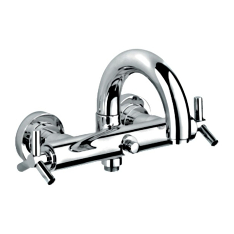
  9. Grohe Kensington 19 265 User manual

Grohe Kensington 19 265 User manual

Other manuals for Kensington 19 265

1

This manual suits for next models

2

Other Grohe Plumbing Product manuals

Grohe Ondus 36 067 User manual

Grohe

Grohe Ondus 36 067 User manual

Grohe BauFlow 29045000 User manual

Grohe

Grohe BauFlow 29045000 User manual

Grohe GRANDERA 20 418 User manual

Grohe

Grohe GRANDERA 20 418 User manual

Grohe Sentosa 19 696 User manual

Grohe

Grohe Sentosa 19 696 User manual

Grohe Euroeco Cosmopolitan E 36 269 User manual

Grohe

Grohe Euroeco Cosmopolitan E 36 269 User manual

Grohe Tectron 37 750 User manual

Grohe

Grohe Tectron 37 750 User manual

Grohe Veris 20 182 User manual

Grohe

Grohe Veris 20 182 User manual

Grohe Talia 19 719 User manual

Grohe

Grohe Talia 19 719 User manual

Grohe Seabury 20 800 User manual

Grohe

Grohe Seabury 20 800 User manual

Grohe Grohtherm 3000 19 691 User manual

Grohe

Grohe Grohtherm 3000 19 691 User manual

Grohe Ondus 20 149 User manual

Grohe

Grohe Ondus 20 149 User manual

Grohe Blue Pure 31087 User manual

Grohe

Grohe Blue Pure 31087 User manual

Grohe Grohsafe 35 237 User manual

Grohe

Grohe Grohsafe 35 237 User manual

Grohe DEFINED 30377000 User manual

Grohe

Grohe DEFINED 30377000 User manual

Grohe Chiara 19 159 User manual

Grohe

Grohe Chiara 19 159 User manual

Grohe LADYLUX 3 CAFE FOOT CONTROL 30 313 User manual

Grohe

Grohe LADYLUX 3 CAFE FOOT CONTROL 30 313 User manual

Grohe 34487000 User manual

Grohe

Grohe 34487000 User manual

Grohe ATRIO 19 291 User manual

Grohe

Grohe ATRIO 19 291 User manual

Grohe Grohtherm 2000 New User manual

Grohe

Grohe Grohtherm 2000 New User manual

Grohe ATRIO 21 046 User manual

Grohe

Grohe ATRIO 21 046 User manual

Grohe Allure F-digital 36 345 User manual

Grohe

Grohe Allure F-digital 36 345 User manual

Grohe Chiara Series User manual

Grohe

Grohe Chiara Series User manual

Grohe QuickFix Start 30530002 User manual

Grohe

Grohe QuickFix Start 30530002 User manual

Grohe Allure F-digital 36 345 User manual

Grohe

Grohe Allure F-digital 36 345 User manual

Popular Plumbing Product manuals by other brands

Moen SANI-STREAM 8797 manual

Moen

Moen SANI-STREAM 8797 manual

Cistermiser Easyflush EVO 1.5 manual

Cistermiser

Cistermiser Easyflush EVO 1.5 manual

Kohler Triton Rite-Temp K-T6910-2A installation guide

Kohler

Kohler Triton Rite-Temp K-T6910-2A installation guide

BEMIS FNOTAB100 Installation instruction

BEMIS

BEMIS FNOTAB100 Installation instruction

Hans Grohe ShowerTablet Select 700 13184000 Instructions for use/assembly instructions

Hans Grohe

Hans Grohe ShowerTablet Select 700 13184000 Instructions for use/assembly instructions

Akw Stone Wash Basin Installation instructions manual

Akw

Akw Stone Wash Basin Installation instructions manual

Enlighten Sauna Rustic-4 user manual

Enlighten Sauna

Enlighten Sauna Rustic-4 user manual

Moen ShowHouse S244 Series quick start guide

Moen

Moen ShowHouse S244 Series quick start guide

Sanela SLWN 08 Mounting instructions

Sanela

Sanela SLWN 08 Mounting instructions

Franke 7612982239618 operating instructions

Franke

Franke 7612982239618 operating instructions

Heritage Bathrooms Granley Deco PGDW02 Fitting Instructions & Contents List

Heritage Bathrooms

Heritage Bathrooms Granley Deco PGDW02 Fitting Instructions & Contents List

Tres TOUCH-TRES 1.61.445 instructions

Tres

Tres TOUCH-TRES 1.61.445 instructions

STIEBEL ELTRON WS-1 Operation and installation

STIEBEL ELTRON

STIEBEL ELTRON WS-1 Operation and installation

Miomare HG00383A manual

Miomare

Miomare HG00383A manual

BELLOSTA revivre 6521/CR1 quick start guide

BELLOSTA

BELLOSTA revivre 6521/CR1 quick start guide

American Standard Heritage Amarilis 7298.229 parts list

American Standard

American Standard Heritage Amarilis 7298.229 parts list

BorMann Elite BTW5024 quick start guide

BorMann

BorMann Elite BTW5024 quick start guide

Moen 1225 quick start guide

Moen

Moen 1225 quick start guide

manuals.online logo
manuals.online logoBrands
  • About & Mission
  • Contact us
  • Privacy Policy
  • Terms and Conditions

Copyright 2025 Manuals.Online. All Rights Reserved.

English .....1
Français .....2
Español .....3
Kensington
Kensington
95.317.031/ÄM 20184509.06
English .....4
Français .....6
Español .....8
19 265
19 265 VP0 19 266
I
S.v.p remettre cette instruction à l'utilisateur de la robinetterie!
Entregue estas instrucciones al usario final de la grifería!
Please pass these instructions on to the end user of the fitting!
19 265
19 265 VP0 19 266
II
3
O2
M
L
N1
FO1
O
N
N
N1
2mm
F1
6
F
7D2 D1
K
J
100 °F
5
81.
2.
D
K
1
A
C
A1
B
2
D1
D
1.
2.
3
F2
E
34 122
34 124
FF1
4F
GH
I
8mm
4
English
Installation
- Remove the two screws (A1) from the fitting template (A),
then remove the template, see fig. [1].
- Unscrew adjusting nut (B) and detach stop ring (C), discard
both parts.
- Install stop ring (D), see fig. [2].
- Fit clamp (D1).
Mounting escutcheon, see figs. [3] and [4].
1.Install the compensation ring (E) if using rough-in
valve 34 122, the ring is not needed for rough-in
valve 34 124, see fig. [3].
2.Push sleeve (F) with the mark (F1) upward onto the mixer
shank, make sure that the marking point (F2) snaps into the
sleeve (F).
3.Slide the escutcheon (G) over the sleeve (F), see fig. [4].
4.Tighten escutcheon with screws (H).
Do not use excessive force to tighten the screws.
5.For assembly of the lever (O) or handle (N), see chapter
"Adjustment".
If thermostat is installed too deep, the fitting depth
can be increased by 1 1/8" (27.5mm) with extension set
Part No. 47 358, see page 2.
Adjustment
Temperature setting, see figs. [5] and [6].
• Before the mixer is put into service, if the mixed water
temperature measured at the point of discharge varies from
the specified temperature set on the thermostat handle.
• After any maintenance operation on the thermoelement.
1.Open volume control (J) and measure the temperature of
the water emerging with a thermometer, see fig. [5].
2.Install the green regulator nut (K) and adjust with a
screwdriver until the water emerging has reached a
temperature of 100 °F.
3.Fit the scale handle (L) so that the 100 °F mark on
the scale ring lines up with the mark (F1) on the
sleeve (F), see fig. [6].
4.Screw on sleeve (L).
5.Screw in set screw (O1, N1) into lever (O) or handle (N).
Slide the cap (O2) on the lever or handle.
6.Attach lever or handle with cap (O2) and secure with set
screw (O1, N1).
7.Tighten the cap (O2) onto the sleeve by hand.
Reversed union (hot on right - cold on left).
Replace thermoelement (47 050) or (47 582), see replacement
parts page 2, ref. No.: 47 282 (1/2") and 47 379 (3/4”).
Temperature limitation
When in proper calibration, the temperature range is limited
to 110 °F. There is a safety check at 100 °F.
If a higher temperature is desired, one can
exceed 100 °F by overriding the safety check.
Prevention of frost damage
When the domestic water system is drained, the thermostat
mixers must be drained separately, since non-return valves
are installed in the hot and cold water connections.
The complete thermostat assembly and non-return valves
must be unscrewed and removed.
Maintenance
Inspect and clean all parts, replace if necessary and grease
with special valve grease.
I.Thermoelement, see fig. [6] to [8] and page 2.
1. Turn scale handle (L) to the 100 °F safety check, see
fig. [6].
2. Unscrew cap (O2).
3. Remove set screw (O1, N1) and detach lever (O) or
handle (N).
4. Unscrew handle sleeve (M) and pull off scale handle (L).
5. Remove screws (H) and escutcheon (G), see fig. [4].
6. Close both isolation valves (I).
7. Pull sleeve (F) from the mixer shank by pressing
down the tongue (D2), see fig. [7].
8. Extract clamp (D1).
9. Pull stop ring (D) until resistance is encountered
(approximately 3/8" [10mm]), see fig. [8].
10. Unscrew stop ring (D) complete with regulator
nut (K).
11. Unscrew thermoelement (47 050, 47 582) with 24mm
open-ended wrench, see page 2.
Readjustment is necessary after every maintenance operation
on the thermoelement, see Adjustment.
II. Non-return valve, see fig. [6] to [8] and page 2.
1. Proceed as for maintenance of thermoelement,
points 1 - 6.
2. Unscrew non-return valve (P) or (Q) with 17mm
socket wrench or 10mm allen wrench, see page 2.
3. Remove non-return valve (Q1) and filter (Q2).
Reassembly should be carried out in reverse order.
Observe the correct mounting position!
Replacement parts, see page 2 (* = special accessories).
Care
Instructions for care of this faucet will be found in the Limited
Warranty supplement