Grouser 4100 User manual

4100 O
4100 O
4100 OWNER
WNER
WNER'
'
'S
S
SM
M
MANUAL
ANUAL
ANUAL
&
&
&
P
P
PARTS
ARTS
ARTS B
B
BOOK
OOK
OOK
755 2nd Ave NW—West Fargo, ND 58102—800-747-6182 / 701-282-7710—grouser@grouser.com—www.grouser.com
Date Purchased
Purchased From
Blade Model Number
Blade Serial Number
Tractor

2
Updated: 5/21/2003
C
ONTENTS
This manual contains information concerning the operation, adjustment, and maintenance of the
4100 blade assembly. You have purchased dependable, long lasting equipment, but only by proper
care and operation can you expect to receive the performance and long service built into our prod-
ucts. Please have all operators read this manual carefully and keep the manual available for ready
reference. If you have any questions or concerns, contact Grouser Products.
T
O
T
HE
O
WNER
Safety Precautions 3
Maintenance 4
Skid Shoe & Tilt Plate Adjustment 4-5
Warranty Information 6
Blade Assemblies 7
Angle System Operating Instructions 8-9
Angle System Parts Diagrams 10-13
No Angle - No Tilt Assembly 14
Quick Attach Lever System 15
Standard Lift System 16-17
Low Profile Lift System 18-19
Lift System Hydraulics 20
Wiring Harness and Electrical System 21
Plumbing Schematic 22
Torque Specifications and Contact Information 23

3
Updated: 5/21/2003
S
AFETY
P
RECAUTIONS
A careful operator is the best operator. Most accidents can be avoided by observing certain
precautions. To help prevent accidents, read and take the following precautions before operating
this equipment. In addition to these precautions, please follow all safety and operational instructions
of your tractor manufacturer.
The Dozer:
1. The 4100 Dozer should be operated only by those who are responsible and instructed to do so.
2. Read the owner’s manual carefully before using this equipment. Lack of operating knowledge
can lead to accidents.
3. Keep the dozer maintained in reliable and satisfactory condition to ensure your safety.
4. Make sure the area is clear of people before moving any equipment.
5. Do not modify or permit anyone else to modify or alter the dozer and its components without
first consulting Grouser Products.
Servicing the Dozer:
1. Read and follow all safety instructions provided by the tractor manufacturer.
2. Always use proper personal safety gear when performing maintenance on equipment.
3. Before servicing, relieve hydraulic pressure, stop engine and fully engage parking brake.
4. Escaping hydraulic fluid under pressure can penetrate skin causing serious injury. If fluid is in-
jected into skin, obtain medical attention immediately.
- DO NOT use your hand to check for leaks. Use a piece of cardboard or paper to search for
leaks.
- Stop the engine and relieve pressure before connecting or disconnecting lines.
- Tighten all connections before starting the engine or pressurizing lines.
Storing the Dozer:
1. Thoroughly clean the dozer before storage. Use paint where necessary to prevent rust.
2. Check the dozer for worn or damaged parts. Install new parts as required.
3. Lubricate all pins and joints.

4
Updated: 5/21/2003
Due to the harsh environment many of our dozer’s operate in, the following
tasks should be performed every 10 hours or less.
• Inspect equipment before operation for existing or potential damages.
• Lubricate all joints with high quality grease.
• Inspect and tighten all bolts to torque specifications on page 23.
• Check replaceable cutting edge for wear ensuring there is enough material to prevent permanent
damage to blade.
• Make sure all non-rotating pins are secured properly.
• Check hydraulic cylinder and hoses for damage or leaks. See page 20 for replacement parts.
• Check skid shoes for wear and replace if necessary. For adjustment, see page 5.
• Inspect all tilt-ways for aggressive wear. See page 5 for tilt plate adjustment.
M
AINTENANCE
Skid Shoe Adjustment:
1. Raise and secure blade to access skid shoe bolts and nuts.
2. Loosen nuts and set skid shoe depth by sliding the shoe back or forth in direction ‘A’ shown on
Figure 2.
3. Once depth is set, tighten bolts to 150 ft-lbs.
Tilt Plate Adjustment:
1. Remove bolts and tilt plates.
2. Add or remove washers as needed to adjust tilt-way clearance in direction ‘B’ shown in Figure 2.
3. Once tilt-way clearance is set, tighten bolts to 640 ft-lbs.
continued on next page
S
KID
S
HOE
AND
T
ILT
P
LATE
A
DJUSTMENT

5
Updated: 5/21/2003
S
KID
S
HOE
AND
T
ILT
P
LATE
A
DJUSTMENT
(C
ONT
.)
Tilt Plate
Skid Shoe
Washers
Adjustment
Track
Figure 1
Skid Shoe
Tilt Plates
B
A
Figure 2

6
Updated: 5/21/2003
Grouser Products warrants to the original purchaser of each item that the product be free
from defects in material and workmanship under normal use and service for a period of one year.
If such equipment is found to be defective within one year, it is the obligation of Grouser Products
under this warranty to repair or replace (exclusive of the cost of labor and transportation), any
equipment or parts, in the judgment of Grouser Products to be defective in material or workman-
ship.
All equipment or parts claimed to be defective in material or workmanship must be made
available for inspection at the place of business of a dealer authorized to handle the equipment
covered by this warranty, or, upon request by Grouser Products, shipped to the Grouser Products
factory in West Fargo, North Dakota. Grouser Products shall have no obligation to bear the cost of
labor or transportation in connection with replacement or repair of any such defective parts in the
setup process.
This warranty covers only defects in material and workmanship. It does not cover deprecia-
tion or damage caused by normal wear, accident, improper assembly, improper adjustments, im-
proper maintenance including lack of proper lubrication, or improper use. Therefore, Grouser Prod-
ucts liability under this warranty shall not be effective or actionable unless the equipment is assem-
bled, maintained and operated in accordance with the operating instructions accompanying the
equipment. Grouser Products shall have no liability if the equipment has been altered or reworked
without the written authorization of Grouser Products.
Grouser Products’ parts, which are furnished under this warranty and properly installed,
shall be warranted to the same extent as the original parts under this warranty if, and only if, such
parts are found to be defective within the original warranty period covering the original equipment.
W
ARRANTY

7
Updated: 5/21/2003

8
Updated: 5/21/2003
4100 H
YDRAULIC
A
NGLE
S
YSTEM
O
PERATING
I
NSTRUCTIONS
If your Grouser blade was purchased with the hydraulic angle option, you will have the ability
to angle the blade 30 degrees left or right. To achieve these angles the two cylinders are designed
to operate independently of each other through an electric diverter valve. To angle the blade to
the left, actuate the tractor hydraulic control lever in the cab with the diverter valve un-powered.
To angle the blade to the right, apply power to the diverter valve and then actuate the tractor hy-
draulic control lever.
The diverter valve has a built-in safety relief valve that allows the cylinder to retract if its inter-
nal pressure exceeds 2000 psi. With this safety feature in place, when either cylinder reaches the
end of its stroke, the safety relief valve will reroute pressure to the opposite cylinder causing it to
extend. While the factory setting on the relief valve is high enough to maintain an angle setting
under full load, this may be cumbersome to some operators, the following are possible adjust-
ments to this remedy this action:
Reduce tractor valve pressure: Some newer tractors allow the service valve pressure to be ad-
justed below the 2000 psi point of the safety relief valve.
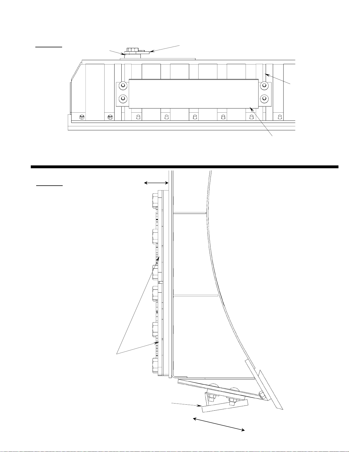
Set the safety relief valve at a higher pressure than tractor: To increase the pressure of
the relief valve install a 0-5,000 psi pressure gauge into base end of right angle cylinder (see pg
20). Loosen the jam nut on the safety valve and tighten the Allen screw ½ turn. Now extend the
right side cylinder out until the safety valve activates, while the safety valve is in function, record
the pressure reading on the gauge. Continue to tighten the Allen screw in ½ turn increments and
record the pressure until a high enough relief setting is obtained. Do not exceed the 3000-psi
operating pressure of the cylinders. Tighten jam nut and remove gauge.
Automatic lever release: In some newer tractors the hydraulic control lever will automatically
release and instantly stop oil flow once the end of the stroke is reached.
CAUTION: Do not bypass the safety relief valve and plumb each cylinder to separate
valves on the tractor.
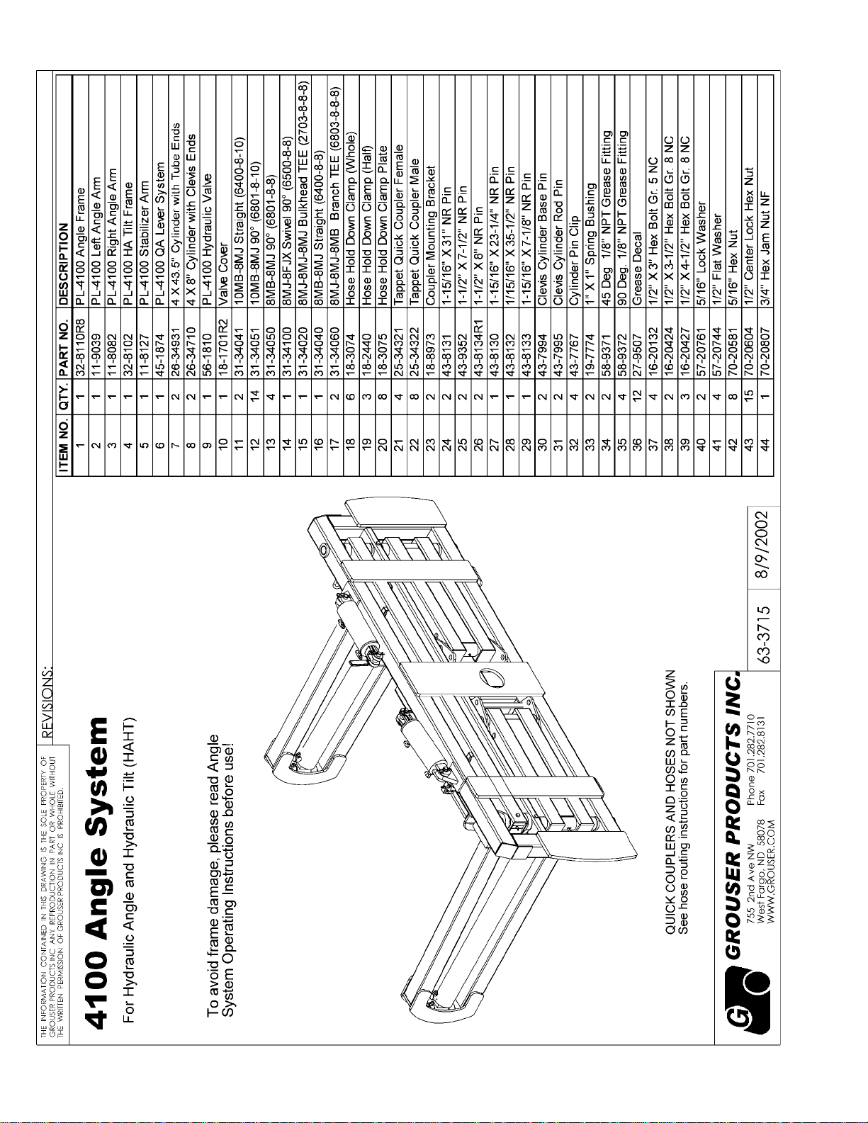
To ensure proper use and life of equipment, it is recommended to have both cylinders closed for
straight ahead dozing and only one cylinder partially or fully extended for angled dozing as shown
in the diagrams below. If the angle system is not used correctly, frame damage may oc-
cur. Some damaged frames can be repaired, please contact Grouser Products for repair instruc-
tions if needed.
Please contact Grouser Products with any questions by:
Phone- 701-282-7710 or 800-747-6182; Fax- 701-282-8131

9
Updated: 5/21/2003
CORRECT
INCORRECT
CORRECT
(Left or Right)

10
Updated: 5/21/2003

11
Updated: 5/21/2003

12
Updated: 5/21/2003

13
Updated: 5/21/2003

14
Updated: 5/21/2003

15
Updated: 5/21/2003

16
Updated: 5/21/2003

17
Updated: 5/21/2003

18
Updated: 5/21/2003

19
Updated: 5/21/2003

20
Updated: 5/21/2003
Table of contents
Other Grouser Farm Equipment manuals
Popular Farm Equipment manuals by other brands

Challenger
Challenger 648 D Original Operator's Manual

Krone
Krone Swadro TC 1000 operating instructions

Anderson
Anderson NWS-660 Operator's manual

enorossi
enorossi RAKE CADDY Series User and maintenance manual

Sulky
Sulky TRAMLINE SE Original instructions

Amazone
Amazone Centaya 3000 Super 1600 operating manual

INRODA
INRODA Light Duty Disc Harrow instruction manual

GREAT PLAINS
GREAT PLAINS BD7600 quick start guide

Hyundai power products
Hyundai power products HYMD500 instruction manual

Haybuster
Haybuster 77 Operating Instructions and Parts Reference

MacDon
MacDon 9200 Operator's manual

Gaspardo
Gaspardo G19502451 Use and maintenance