manuals.online logo
Brands
  1. Home
  2. •
  3. Brands
  4. •
  5. Grouser
  6. •
  7. Farm Equipment
  8. •
  9. Grouser AG PRO PLUS HD User manual

Grouser AG PRO PLUS HD User manual

Date 9-23-2015PN: 63-18828
AG PRO PLUS HD
Owner’s Manual
&
Parts Book
Purchase Date
Serial Number
Model Number
Tractor Model
Dealer
2
Description Page
To The Owner, Maintenance 2
Safety Precautions, Torque Specications & Unpacking Components 3
Assembling Lift Components & Initial System Startup 4
Lift System 5
Connecting & Disconnecting the Blade, Skid Shoe and Tilt Plate Adjustment 6
Blade Assembly & NANT Blade Assembly 7
Hydraulic Instructions, Angle System & 2-Lever Angle System Operating Instructions 8
Relief Valve Instructions 8-9
Angle / Tilt Function Abbreviation Key 10
Angle Hydraulic Components 10
No Angle - Hydraulic Tilt System & Hydraulics 11
Quick Attach System 12-13
Hydraulic Angle - Hydraulic Tilt & Hydraulic Angle - No Tilt System 14-15
Hydraulic Angle - Hydraulic Tilt & Hydraulic Angle - No Tilt Hose Routing (Blade Side) 16-17
Hydraulic Angle - 2 Lever System Hose Routing (Blade Side) 18-19
Tractor Side Hydraulic Hose Routing 20
Wire Harness 21
Hydraulic Schematic 22
2- Lever Hydraulic Schematic 23
Contact Us, Improvements, & Warranty 24
Contents
To The Owner
This manual contains information concerning the operation, adjustment, and maintenance of the Ag Pro Plus
HD blade assembly. You have purchased dependable, long lasting equipment, but only by proper care and
operation can you expect to receive the performance and long service built into our products. Please have
all operators read this manual carefully and keep the manual available for ready reference. If you have any
questions or concerns, contact Grouser Products.
Maintenance
Due to the harsh environment many of our equipment operates in, the following tasks
should be performed every 10 hours or less.
• Inspect all equipment before operation for existing or potential damages.
• Lubricate all joints with high quality grease.
• Inspect and tighten all bolts to torque specications on page 3.
• Check replaceable cutting edge for wear ensuring there is enough material to prevent permanent damage
to the blade.
• Make sure all non-rotating pins are secured properly.
• Check hydraulic cylinders and hoses for damage or leaks. For replacement parts, see hydraulic pages for
your specic system.
• Check skid shoes for wear and replace if necessary. For adjustment, see page 6.
• Inspect all tilt-ways for aggressive wear. See page 6 for tilt plate adjustment.
3
Safety Precautions
A careful operator is the best operator. Most accidents can be avoided by observing certain precautions. To
help prevent accidents, read and take the following precautions before operating this equipment. In addition
to these precautions, please follow all safety and operational instructions of your tractor manufacturer.
The Dozer:
1. The Ag Pro Plus HD Dozer should be operated only by those who are responsible and instructed to do so.
2. Read the owner’s manual carefully before using this equipment. Lack of operating knowledge can lead to
accidents.
3. Keep the dozer maintained in reliable and satisfactory condition to ensure your safety.
4. Make sure the area is clear of people before moving any equipment.
5. Do not modify or permit anyone else to modify or alter the equipment and its components without rst
consulting Grouser Products.
Servicing the Dozer:
1. Read and follow all safety instructions provided by the tractor manufacturer.
2. Always use proper personal safety gear when performing maintenance on equipment.
3. Before servicing, relieve hydraulic pressure, stop engine and fully engage parking brake.
4. Escaping hydraulic uid under pressure can penetrate skin causing serious injury. If uid is injected into
skin, obtain medical attention immediately.
– DO NOT use your hand to check for leaks. Use a piece of cardboard or paper to search for leaks.
– Stop the engine and relieve pressure before connecting or disconnecting lines.
– Tighten all connections before starting the engine or pressurizing lines.
Storing the Dozer:
1. Thoroughly clean the dozer before storage. Use paint where necessary to prevent rust.
2. Check for worn or damaged parts. Install new parts as required.
3. Lubricate all pins and joints.
Torque Specications
All bolts should be tightened to the specications that are stated. If specications are not stated, follow torque
charts below.
Torque - Dry (ft–lbs)
SAE Grade 5 SAE Grade 8
Size UNC UNF UNC UNF
5/16 17 19 24 27
3/8 30 35 45 50
7/16 50 55 70 80
1/2 75 85 110 120
9/16 110 120 150 170
5/8 150 170 210 240
3/4 260 300 380 420
7/8 430 470 600 670
1 640 720 910 1020
Torque - Dry (ft-lbs)
Size Grade 10.9
M18 x 2.50 284
M20 x 2.50 401
M22 x 2.50 547
M24 x 3.00 694
Unpacking Components
Unstrap and remove any components that are attached for shipping. If any components are missing, call
Grouser.
4
Assembling Lift Components
Install undercarriage per the tractor specic mounting instructions. Some assembly of Lift system components is
necessary. Follow the steps listed below. Refer to Page 5 for the correct hardware and orientation of parts.
Remove all pins on each side of the undercarriage.
Position the lift frame between the two plates on both sides of the undercarriage.
Align the lift frame to the bottom holes of the undercarriage and attach with the proper pins and hardware.
Lift the end of the cylinders up and attach to the undercarriage with the proper pins and hardware.
Attach the top arms to the top of the undercarriage with the proper pins and hardware.
Attach the male quick attaches to the lift frame and top arms with the proper pins and hardware.
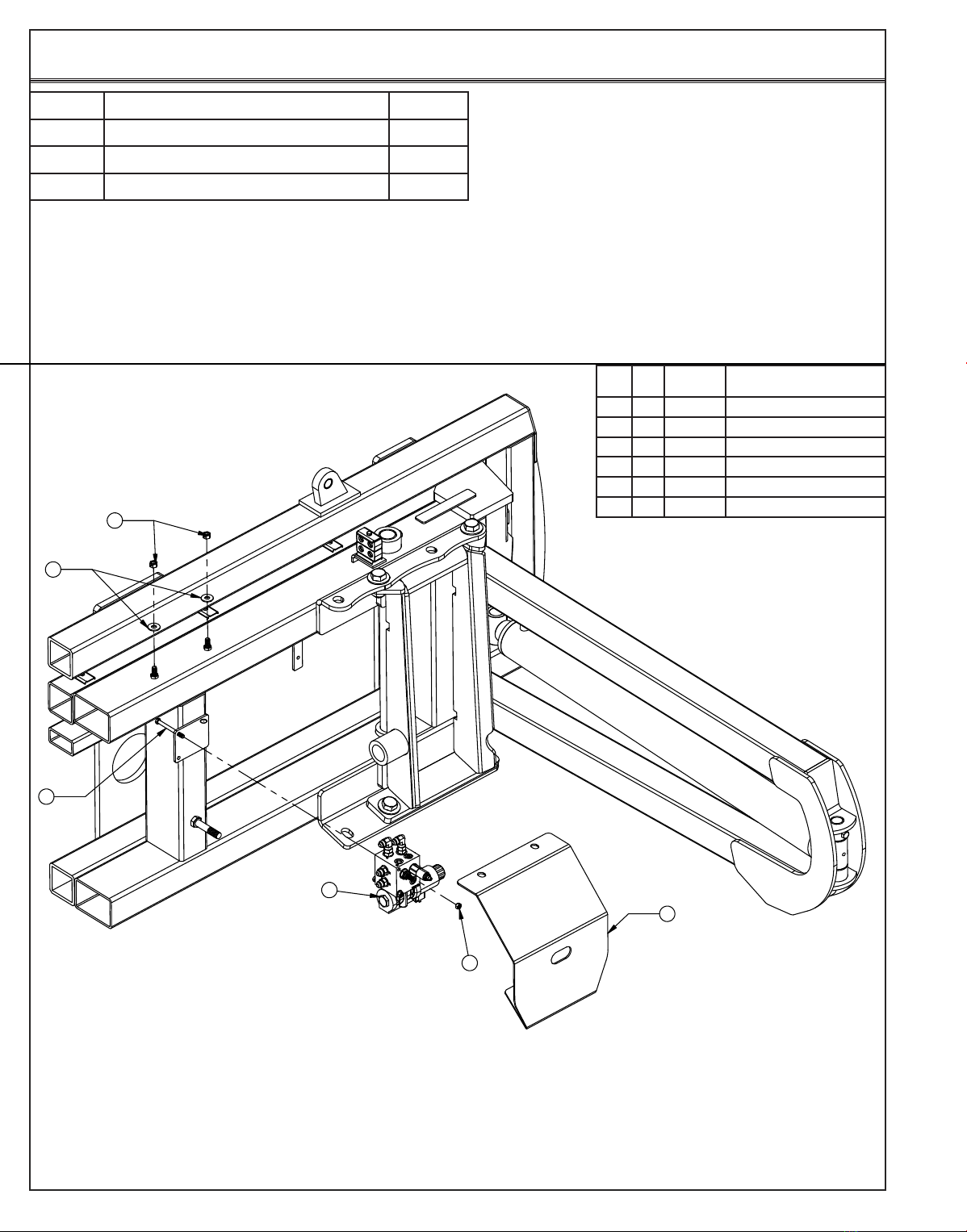
If the quick couplers and coupler mount are not already attached to the left top arm, attach the coupler mount to
the top arm with 2 - 1/2” Carriage bolts and 2 - 1/2” Nuts. See Page 20 for proper orientation.
Take the lift hoses that are already attached to the bulkhead ttings on the undercarriage and attach them to the
lift cylinders.
Note: For Step #9-15, refer to Page 20 for further information on hose routing and hose positions. The
amount and location of the female couplers is determined by functions the blade is set up for.
Run the remaining hoses on the undercarriage to the top arm and attach a 90° tting to all the hoses.
Install a female quick coupler onto each 90° tting from the previous step.
Install each coupler into the designated hole on the coupler mount and hold them in place with the coupler
retainer plate, 3/8” x 3/4” bolts and 3/8” ange nuts.
Take the long hoses and attach each one to a tting at the center of the undercarriage.
Mark each hose clearly so that once the hoses are routed to the back of the tractor, it’s easy to determine what
cylinder base or rod end they are connected to.
Route the hoses thru the hose loops on the undercarriage.
Continue to route the hoses thru the tractor and plug into the rear remotes on tractor. Keep away from all moving
parts.
If applicable, attach the male blade break away end of the wire harness to the coupler mount. Hold in place with
a zip tie. Run the switch end of the wire harness up into the cab of the tractor.
Locate the keyed and fused power supply. Connect the red wire to power and the black to ground. Install
provided switch into an open switch hole in the right overhead console or another convenient place in the tractor.
Connect the wire harness to the switch.
Get the blade ready to hook up by removing the 3/4” pin (#19 on Page 7) so that the skid shoes can move freely.
The blade will lean back further for easier connection onto the male quick attaches. Store the pin in the empty
hole right behind the hole you just took the pin out of.
Pull the pin puller handle on the left side of the quick attach system towards the outside of the blade to open the
quick attach system. Refer to Page #12-13 for further clarication on the quick attach system.
Drive the tractor forward slowly until the top edge of the male quick attach is under the top lip of the female quick
attach already on the blade assembly.
Lift the male quick attaches up till the blade is off the ground and the female quick attaches are against the front
of the male quick attaches.
Shut off machine and set the parking brake.
Move the pin puller handle on the left side of the blade assembly towards the center of the blade to lock the
blade in place and use the latch to the lock the handle in place.
Plug the male couplers into the female couplers on the top arm. Refer to Page #20 for proper coupler locations
for all functions. If applicable, plug the male blade break away end of the wire harness into the female blade
break away end of the wire harness on the top arm.
Lock the Mushroom Skid Shoe Link back in place with the 3/4” pin you moved in Step #18 above.
To disconnect the blade, see Page 6.
Initial System Startup
Start the tractor and run the blade thru all the functions. If any function does not work properly, bleeding of the
system may be required. If problem still persists, call Grouser Products.
1.
2.
3.
4.
5.
6.
7.
8.
9.
10.
11.
12.
13.
14.
15.
16.
17.
18.
19.
20.
21.
22.
23.
24.
25.
26.
5
Lift System
Hoses Are Not Drawn To Scale
Item
No. Qty. Part No. Description
21B 235-30963 318” (26.5’) x 5/8” -10JIC/-10JIC Hose
21C 235-30976 293” (24.42”) x 5/8” -10JIC/-10JIC Hose w/165” Cordura
22 2 35-31928 57” x 5/8” -10JIC/-10JIC Hose W/Cordura
23 2 35-31934 75” x 5/8” -10JIC/-10JIC Hose W/Cordura
24 2 43-14725 AG Pin (Lift Frame / UC)
25 4 43-18120 Ag Pro + UC Top Pin (2” x 7.13”)
26 2 43-18175 Ag Pro + Lift Cyl Pin (2” x 6.38”)
27 2 43-18127 Ag Pro + Top Arm/QA Pin (2” x 7.5”)
28 2 43-18635 Ag Pro + QA Pin (2.5” x 7.50”)
29 145-18130-L Ag Pro + Series Male QA - Left
30 1 45-18130-R Ag Pro + Series Male QA - Right
31 2 57-1530 3” OD x .75” ID x .25” Flat Washer
32 2 57-1811 2” Narrow Rim Washer
33 2 57-20740 1/4” Flat Washer
34 10 57-20747 3/4” Flat Washer
35 12 58-9369 Grease Zerk 1/8” NPT Straight
36 10 70-20599 1” Hex Nut Gr 8 NC
37 2 70-20607 3/4” Hex Center Lock Nut Gr 2 NC
38 2 70-20610 1/4” Nyloc Hex Nut NC
39 270-20808 7/8” Hex Jam Nut NF
Item
No. Qty. Part No. Description
1 1 11-19150-L HD Top Arm - Left
2 1 11-19150-R HD Top Arm - Right
3 2 16-20002 1/4” x 3/4“ Hex Bolt Gr 5 NC
4 4 16-20216 3/4” x 1-1/2” Hex Bolt Gr 5 NC
5 4 16-20217 3/4” x 1-3/4” Hex Bolt Gr 5 NC
6 4 16-20220 3/4” x 2-1/2” Hex Bolt Gr 5 NC
7 10 16-20566 1” x 4” Hex Bolt Gr 8 NC
8 8 19-13515 3/4” ID - Non Rotating Pin Spacer Bushing
9219-13525 2.75 x 2.50 x 4.75 Spring Bushing
10 2 25-34342 Tappet Quick Coupler Male
11 226-34751 5 x 18 Cylinder Tube Ends
12 2 31-11699-10-10 JIC Union (2403-10-10)
13 2 31-34031 Bulkhead Run Tee JIC (2704-10-10-10)
14 2 31-34052 Straight Thread Elbow 90° JIC x O-Ring (6801-10-10)
14A 2 31-34152 Straight Thread Elbow 45° JIC x O-Ring (6802-10-10)
15 4 31-6400-10-08 Straight JIC x O-Ring (6400-10-8)
16 1 32-19120 Ag Pro Plus HD - Lift Frame
17 2 34-12932 Cylinder Saddle (ZR518)
18 2 34-16578 Hose Clamp
19 134-14961 Manual Canister
20 2 35-18240 Ag Pro Plus - Steel Line (Lift Cylinder)
Item #B for Versatile and Challenger Tractors and Item #C for Steiger, New Holland, Claas and JD 9R Tractors.
Item #A for Claas Tractors.
39
17
8
4
5
32
25
16
8
8
8
5
35
4
24
26
34
27
34
25
34
31
35
35
37
35
19
30
33
9
35
29
35
13
34
2
10
38
14
18
3
612
15
15
11
22
6
20
1
21
28
34
7
23
36

Other Grouser Farm Equipment manuals

Grouser Ag Pro Plus Undercarriage User manual

Grouser

Grouser Ag Pro Plus Undercarriage User manual

Grouser 4100 User manual

Grouser

Grouser 4100 User manual

Grouser Ag Pro 3-5 NANT User manual

Grouser

Grouser Ag Pro 3-5 NANT User manual

Popular Farm Equipment manuals by other brands

Schaffert Rebounder Mounting instructions

Schaffert

Schaffert Rebounder Mounting instructions

Stocks AG Fan Jet Pro Plus 65 Original Operating Manual and parts list

Stocks AG

Stocks AG Fan Jet Pro Plus 65 Original Operating Manual and parts list

Cumberland Integra Feed-Link Installation and operation manual

Cumberland

Cumberland Integra Feed-Link Installation and operation manual

BROWN BDHP-1250 Owner's/operator's manual

BROWN

BROWN BDHP-1250 Owner's/operator's manual

Molon BCS operating instructions

Molon

Molon BCS operating instructions

Vaderstad Rapid Series instructions

Vaderstad

Vaderstad Rapid Series instructions

HighLine BM1400 operating manual

HighLine

HighLine BM1400 operating manual

GSi PNEG-2314 installation manual

GSi

GSi PNEG-2314 installation manual

Checchi & Magli TEXDRIVE owner's manual

Checchi & Magli

Checchi & Magli TEXDRIVE owner's manual

Amazone Cenius 4003-2TX operating manual

Amazone

Amazone Cenius 4003-2TX operating manual

MASSEY FERGUSON MF 9313S Operator's manual

MASSEY FERGUSON

MASSEY FERGUSON MF 9313S Operator's manual

Cima BLITZ Maintenance Instruction

Cima

Cima BLITZ Maintenance Instruction

Amazone CombiDisc 3000 Original operating manual

Amazone

Amazone CombiDisc 3000 Original operating manual

HE-VA Disc-Roller XL Contour Operating instructions/spare parts list

HE-VA

HE-VA Disc-Roller XL Contour Operating instructions/spare parts list

AGT AGT-SSFM product manual

AGT

AGT AGT-SSFM product manual

Milestone 72-84 manual

Milestone

Milestone 72-84 manual

KUHN Hector 3000 Complementary instructions

KUHN

KUHN Hector 3000 Complementary instructions

Krone X-Disc 6200 operating instructions

Krone

Krone X-Disc 6200 operating instructions

manuals.online logo
manuals.online logoBrands
  • About & Mission
  • Contact us
  • Privacy Policy
  • Terms and Conditions

Copyright 2025 Manuals.Online. All Rights Reserved.