Grove Audio GMS-744 User manual

Copyright 2021 –Grove Audio LLC
All rights reserved
1
GMS-744 Multichannel MIDI/CV
Converter
PRELIMINARY OPERATION MANUAL
Ver. 1.1 - April 8 2021
Grove Audio LLC
Copyright 2021 –All Rights Reserved

Copyright 2021 –Grove Audio LLC
All rights reserved
2
INTRODUCTION
The Multichannel MIDI/CV Converter module is designed to convert MIDI note commands into
corresponding analog voltage level outputs to be used by devices such as voltage controlled oscillators in
analog synthesizers. In addition to a changing pitch voltage on one channel, the module can also supply
a analog voltage corresponding to the MIDI velocity information or mapped to any MIDI CC voltage.
These analog voltages can be used to vary the response of envelope generators to allow the channels
dynamics to be controlled by keyboard velocity information or other voltage controllable parameters such
as filter cutoff frequency or resonance.
BASIC FUNCTIONS
The GMS-744 Multichannel MIDI/CV converter contains eight complete converter channels, each channel
capable of producing an analog output and a gate output. Depending on how MIDI channels are mapped
to output channels using screen menus, various multivoice operation modes can be configured. The
default mode of operation configures the module as four independent channels, each channel having a
pitch CV, a velocity CV, a gate signal, and a trigger signal which is a 25 millisecond pulse occurring when
a note start command is received. As an example of other configurations that can be programmed,
assume that a polyphonic combination of keys needs to be routed to 4 different CV outputs. This is done
by assigning one MIDI input channel to 4 output channels. In this case, the gate outputs can be assigned
to separate gate outputs or they can all be sent to the same gate output to trigger a downstream

Copyright 2021 –Grove Audio LLC
All rights reserved
3
paraphonic arrangement of filter, envelope generator and contour VCA.
DIVERSE INPUT AND OUTPUT CAPABILITY
MULTIVOICE OPERATING MODES
•Two channels with gate and trigger
•Three or four channels with gate
•Two channels with separate sequential MIDI channel numbers
•Four channels with separate sequential MIDI channel numbers
•Split keyboard with C0-B1 on ch. 1 and C2-C5 on ch. 2

Copyright 2021 –Grove Audio LLC
All rights reserved
4
ADDITIONAL FEATURES
A front panel selector allows setting the base MIDI channel on which the module listens. If the setting is
not modified by system commands received on the port, the channel also serves as the default analog
output channel. Depending on the selected operating mode, additional channels are assigned following
the channel selected on the front panel switch.
The MIDI clock on the input channel is divided internally and output on the MIDI CLOCK output jack.
Divisor ratio set by turning mode switch to the desired ratio and pressing the front panel set divisor
pushbutton.
OPERATING MODE TABLE
Operating mode is selected by a front panel 16 position rotary switch.
MODE
FUNCTION
1
2 Ch. Independent
Note CV, Velocity CV, Gate, Trigger
Successive MIDI Channels
2
2 Ch. Polyphonic
Note CV, Velocity CV, Gate, Trigger
Common MIDI Channel
3
4 Ch. Polyphonic
Note CV, Gate
Common MIDI Channel
4
4 Ch. Polyphonic
Note CV, Common Gate
Common MIDI Channel
5
4 Ch. Independent
Note CV, Gate
Succesive MIDI Channels
6
2 Ch. Independent - Legato On
Note CV, Velocity CV, Gate, Trigger
Successive MIDI Channels
7
1 Ch. with Pitchbend, Mod Wheel
Note CV, Velocity CV, Pitchbend CV, Mod Wheel CV, Gate, Trigger
8
1 Ch., Legato On with Pitchbend, Mod Wheel
Note CV, Velocity CV, Pitchbend CV, Mod Wheel CV, Gate, Trigger
9
2 Ch. Independent - Split Keyboard
Ch. 1 (C0-B1) Note CV, Gate; Ch. 2 (C2-C5) Note CV, Gate
Common MIDI Channel
10
2 Ch. Independent, Legato On - Split Keyboard
Ch. 1 (C0-B1) Note CV, Gate; Ch. 2 (C2-C5) Note CV, Gate
Common MIDI Channel
16
Test/Tuning
Common Note CV and common Gate on all outputs
Current MIDI Channel
MIDI CLOCK OUTPUT
If the input MIDI stream contains the MIDI clock (24ppqn clock), the module can be used to output the
clock to external devices, divided by a preset factor. The clock is output through the front panel MIDI CLK
jack. This is a stereo jack with the clock appearing as a 0-5V square wave on the tip connection. On the
ring of the jack is a run/stop signal which can be configured to use the MIDI run/stop/reset real-time
commands or a note message controlled run/stop command.

Copyright 2021 –Grove Audio LLC
All rights reserved
5
The division factor is controlled by the module programming grid Group 1. There is also a toggle bit to
enable the MIDI clock note control. The factory default is a division ratio of 12 (1:8) which will give one
clock per eighth note.
MIDI INPUT CONNECTIONS
MIDI note commands and other control commands can enter the module using either a standard MIDI 5
pin DIN connector or through the USB connector as USB MIDI.
USB DEVICE/USB HOST OPERATION
The USB connector mode is selected using a panel toggle. In DEV mode, the USB port acts like a USB
device when connected to an external USB host such as a computer in which case, it acts like an external
USB MIDI device such as a USB connected synthesizer that accepts and interprets MIDI note
commands.
In the HOST mode, the module can host other USB devices such as keyboard controls, alleviating the
need for external computer host support. Devices detected by the module during enumeration of the USB
bus are displayed in an on-screen router and can be virtually connected either to or from an external
device to resources with the module or used to pass USB commands through the module to a different
external USB device.
When using the HOST mode, the internal enumerator will also support devices requiring up to 500 mA of
bus power. The enumerator also supports connected USB hubs. If more than 500 mA of external power is
needed by devices, a powered hub should be used.
TECHNICAL SPECIFICATIONS GMS-742
Each Channel
Voltage Scale
1 Volt/Octave - .0833
Volts/Semitone

Copyright 2021 –Grove Audio LLC
All rights reserved
6
MIDI Note Range
Note number 0 - 127
produces -4.0 V to +6.0 V
0 V = MIDI Note #48 = C4
(starting note for zero
volts is presettable)
D/A Converter Output
16 Bits; full-scale range
+-10 V
Gate/Trigger Output
0 - +5 V Gate width:
duration of note Trigger
width: 25 msec.
Module Power
+15 Volts 25 mA., -15
Volts 25 mA., +5 Volts
100 mA
Module Size
Panel height - 8.75
inches (222 mm); Panel
width - 2.125 inches (54
mm); Depth (behind
panel) 3.75 inches (96
mm)
MODULE PROGRAMMING OPTIONS
Certain module functions can be programmed by using the mode selector switch and a front panel toggle
switch. To enter the programming mode, press and hold the toggle switch to the right (PGM) position for
approximately two seconds until the Gate 1 LED starts to flash. This indicates that the module is in the
programming mode. By briefly pressing the toggle switch to the right and releasing it, the program group
can be selected. The Gate 2, Trig 1, and Trig 2 LEDs will successively flash, indicating that the
corresponding program group is selected. There are four program groups with 16 options per group. The
table below describes the functions controlled by this arrangement.
Once the option is programmed, its current state is stored in a non-volatile memory and will be restored
the next time the module is powered. One of the program options can be selected to return all settings to
the factory defaults.
Within a group, to select the option to be programmed, turn the mode selector switch to the appropriate
number and then press the toggle switch to the right (PGM) position for approximately two seconds or
until the LED stops flashing and remains lit. Then release the toggle switch. The LED will go off after
approximately one second indicating successful programming of the option. Rotate the Mode selector
switch back to the operation mode that was being used.
PROGRAMMABLE CONTROLS GRID
POS
FUNCTION
GROUP 1
Gate1
POS
FUNCTION
GROUP 2
Gate2
1
1/96 24ppqn rate (not implemented)
1
Pitchbend range +- ½ semitone
2
1/48 clock div
2
Pitchbend range +- 1 semitone
3
1/48 dotted clock div (not implemented)
3
Pitchbend range +- 2 semitone (default)
4
1/32 clock div
4
Zero volts at C4
5
1/16 clock div
5
Zero volts at C3

Copyright 2021 –Grove Audio LLC
All rights reserved
7
6
1/16 dotted clock div
6
Zero volts at C2
7
1/8 clock div (default)
7
Zero volts at C1 (default –Q104 mode)
8
1/8 dotted clock div
8
Disable Pitchbend for mode 7&8
(default)
9
1/4 clock div
9
Enable Pitchbend for mode 7&8
10
1/4 dotted clock div
10
Disable continuous MIDI clock (default)
11
1/2 clock div
11
Enable continuous MIDI clock
12
1/2 dotted clock div
12
Disable RUN/STOP pulse mode
(default)
13
1/1 clock div
13
Enable RUN/STOP pulse mode
14
Not used
14
Auxiliary gate outputs disabled
(default)
15
Disable MIDI clock note control
15
Auxiliary gate outputs enabled
16
Enable MIDI clock note control
16
Reset system defaults
POS
FUNCTION
GROUP 3
Trig1
POS
FUNCTION
GROUP 4
Trig2
1
Legato Mode disabled
Coming soon
2
Legato Mode enabled (default)
INTERNAL GATE CONNECTIONS
There are four internal gate output connections that can be used as gates or triggers depending on the
current operating mode setting. This picture shows their location:

Copyright 2021 –Grove Audio LLC
All rights reserved
8
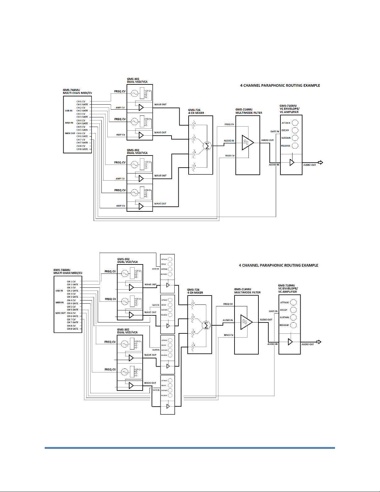
As an example of the use of these outputs, in the four independent channel with common gate and trigger
mode, these outputs could be used to gate each voice through a VCA corresponding to it. Then the VCA
outputs could be mixed and fed through a common VCA controlled by an envelope generator gated and
triggered by the common gate and trigger outputs on the front panel.
RUN/STOP REALTIME MESSAGES AND MIDI NOTE CONTROL
An external control line on the ring of the MIDI CLK connector supplies a 0-5 V pulse or level waveform
that can be used to gate an external clock or sequencer. The line can be set by programmable switch to
be high from the time the RUN realtime message or MIDI note command is received until the STOP
realtime message or MIDI note command is received. The output can be set to be either a level or pulse
depending on the needs of the controlled device. By using this line and the MIDI clock signal on the tip of
the same connector, the external device can be synchronized with software sequencers.
When using the MIDI note command to control the external control line, the internal logic will only respond
to MIDI note messages sent on the MIDI channel which is one channel above the highest MIDI channel
used by the current mode. For example, if Mode 1 is selected, the module responds to MIDI channels one
and two to produce the CV and velocity signals and to MIDI channel 2 channels higher than the value set
on the front panel MIDI channel selector switch for the RUN/STOP note commands. If mode 5 is selected,
the RUN/STOP note commands should be sent on a MIDI channel 4 channels higher than the value set
on the front panel MIDI channel selector switch.

Copyright 2021 –Grove Audio LLC
All rights reserved
9
EXAMPLE PATCHES
4 Channel Paraphonic
4 Channel Paraphonic with Envelope Generator controlled Voice Gating

Copyright 2021 –Grove Audio LLC
All rights reserved
10
4 Voice Polyphonic

Copyright 2021 –Grove Audio LLC
All rights reserved
11
INSTALLING PROGRAM UPDATES
The process for installing program files in the GMS-742a MIDI to CV module using the Microchip HID
bootloader client is described below:
1. Move the entire folder called "usb_bootloader_client_win" to the host machine. It is not necessary to
install the bootloader client.
2. The module must be powered and the miniB USB connector on the module main board must be
accessible.
3. Move the jumper block on pin 8 of the 8pin MTA-100 connector in the upper left corner of the main
board so that pins 7 and 8 are connected. This enables the on-board programming mode.
4. Power up the module. The LED D3 should light steadily to indicate the module is ready to
communicate with the HID bootloader client.
5. Open the bootloader client folder and find the file HIDBootloader. Double click this file to run it.
6. Connect a USB type A cable from the host computer and plug the miniB end of the cable into the USB
connector on the module. There may be some preliminary communication and installation of drivers.
Eventually, a message should appear on the status window of the bootloader client indicating that a
device has been detected and is ready to install files. The LED D3 on the module will flash periodically to
indicate that it is ready.
7. Click on the file menu tab and select Import Hex file option.
8. When a file dialog window opens, navigate to the location of the module hex file to be loaded.
9. Once the file is successfully imported, click on the Program tab and select the Erase, Program, Verify
option.
10. Status messages indicating the progress of the transfer should appear.
11. Once the transfer is completed, power down the module.
12. Move the jumper from pins 7 and 8 to pin 8.
13. Power up the module and the new program version should start running.
Table of contents
Other Grove Audio Media Converter manuals