Kramer FC-102Net User manual

Kramer Electronics Ltd.
FC-101Net, FC-102Net –Contents
i
Contents
Introduction 1
Getting Started 1
Overview 2
Typical Applications 3
Defining FC-101Net and FC-102Net Dual Dante Interface 4
Mounting FC-101Net / FC-102Net 6
Connecting the Devices 7
Connecting FC-101Net 7
Connecting FC-102Net 8
Connecting the FC-101Net Output to an Unbalanced Stereo Audio Acceptor 8
Connecting an Unbalanced Stereo Audio Source to the FC-102Net Input 9
Connecting to FC-101Net / FC-102Net via RS-232 9
Setting FC-102Net DIP-switches 10
Upgrading the Firmware 11
Technical Specifications 12
Default Communication Parameters 13
Protocol 3000 14
Understanding Protocol 3000 14
Protocol 3000 Commands 15
Result and Error Codes 17

Kramer Electronics Ltd.
FC-101Net, FC-102Net –Introduction
1
Introduction
Welcome to Kramer Electronics! Since 1981, Kramer Electronics has been providing a world
of unique, creative, and affordable solutions to the vast range of problems that confront the
video, audio, presentation, and broadcasting professional on a daily basis. In recent years, we
have redesigned and upgraded most of our line, making the best even better!
Getting Started
We recommend that you:
•Unpack the equipment carefully and save the original box and packaging materials for
possible future shipment.
•Review the contents of this user manual.
Go to www.kramerav.com/downloads/FC-101Net or www.kramerav.com/downloads/FC-
102Net to check for up-to-date user manuals, application programs, and to check if
firmware upgrades are available (where appropriate).
Achieving the Best Performance
•Use only good quality connection cables (we recommend Kramer high-performance,
high-resolution cables) to avoid interference, deterioration in signal quality due to poor
matching, and elevated noise levels (often associated with low quality cables).
•Do not secure the cables in tight bundles or roll the slack into tight coils.
•Avoid interference from neighboring electrical appliances that may adversely influence
signal quality.
•Position your Kramer FC-101Net / FC-102Net away from moisture, excessive sunlight
and dust.
Safety Instructions
Caution:
•This equipment is to be used only inside a building. It may only be connected to other
equipment that is installed inside a building.
•For products with relay terminals and GPI\O ports, please refer to the permitted rating
for an external connection, located next to the terminal or in the User Manual.
•There are no operator serviceable parts inside the unit.
Warning:
•Do not open the unit. High voltages can cause electrical shock! Servicing by qualified
personnel only.

Kramer Electronics Ltd.
FC-101Net, FC-102Net –Introduction
2
Recycling Kramer Products
The Waste Electrical and Electronic Equipment (WEEE) Directive 2002/96/EC aims to reduce
the amount of WEEE sent for disposal to landfill or incineration by requiring it to be collected
and recycled. To comply with the WEEE Directive, Kramer Electronics has made
arrangements with the European Advanced Recycling Network (EARN) and will cover any
costs of treatment, recycling and recovery of waste Kramer Electronics branded equipment on
arrival at the EARN facility. For details of Kramer’s recycling arrangements in your particular
country go to our recycling pages at www.kramerav.com/support/recycling.
Overview
Congratulations on purchasing your Kramer FC-101Net Dual Dante Interface decoder and
FC-102Net Dual Dante Interface encoder.
FC-101Net is a compact 2-channel Dante™ decoder with 2 balanced mono audio outputs on
3-pin terminal blocks. It enables connecting non-Dante devices, such as amplifiers and
powered speakers, to a Dante network and enables volume control.
FC-102Net is a compact 2-channel Dante™ encoder with 2 balanced mono audio inputs on 3-
pin terminal blocks that enables connecting non-Dante sources, such as microphones,
laptops and players to a Dante network. It supports line level and microphone level sources
and can provide 48V phantom power per input. FC-101Net and FC-102Net are powered over
Ethernet from any standard PoE providing network switch.
FC-101Net and FC-102Net provide exceptional quality, and advanced and user-friendly
operation.
Exceptional Quality
•Professional, Studio Grade Signal Conversion Technology –Includes the latest
generation 32-bit advanced Digital Analog Converter architecture to achieve excellent
dynamic performance and improved tolerance to clock jitter. Maintains the quality of the
original audio signal with selectable sampling rates up to 96kHz.
•Dante Network Interface.
•PoE Acceptor.
Advanced and User-friendly Operation
•Output Volume Control.
•Versatile Control –Via the Dante IP control matrix and Kramer Protocol 3000 via
RS-232 connection.
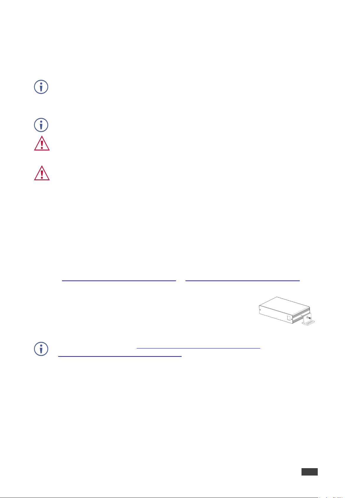
•Easy Installation –Single twisted-pair cable for signal and power wiring. Compact
PicoTOOLS® fan-less enclosure for device-back mounting, or side-by-side mounting of
4 units in a 1U rack space with the recommended rack adapter.

Kramer Electronics Ltd.
FC-101Net, FC-102Net –Introduction
3
Typical Applications
FC-101Net and FC-102Net are ideal for the following typical applications:
•Classrooms.
•Retail.
•Small to mid-size meeting rooms.
•Boardrooms.
Controlling your FC-101Net / FC-102Net
Control your FC-101Net / FC-102Net:
•By RS-232 serial commands transmitted by a touch screen system, PC, or other serial
controller.
•Via the Dante IP control matrix.

Kramer Electronics Ltd.
FC-101Net, FC-102Net –Defining FC-101Net and FC-102Net Dual Dante Interface
4
Defining FC-101Net and
FC-102Net Dual Dante Interface
This section defines FC-101Net and FC-102Net.
FC-101Net:
Figure 1: FC-101Net Dual Dante Interface Decoder
#
Feature
Function
ON LED
Lights green when the device receives power.
SYS LED
Lights green when Dante network is available; red if an error has occurred.
SYNC LED
Lights green for digital audio normal operation.
Flashes green when this unit is the Master clock.
Lights red if an error has occurred.
Dante PoE RJ-45
Port
Connect to the Dante audio source via the Network and provide Power over
Ethernet (PoE) to the device.
By default, DHCP is enabled.
DEF Push Button
To reset/reboot the device, press and release the button.
To reset to factory settings:
FC-101Net –Press and hold the button for 30 seconds.
FC-102Net –Press and hold the button for at least 5 seconds.
OUT 1 5-pin
Terminal Block
Connector
Connect to a single balanced stereo audio output together with OUT 2, or to a
mono output (+, –, G).
OUT 2 5-pin
Terminal Block
Connector
Connect to a single balanced stereo audio output together with OUT 1, or to a
mono output (+, –, G).
RS-232 3-pin
Terminal Block
Connector
Connect to a serial controller to control this device.
Dual Dante Interface
SYS SYNCON DEF
RS-232OUT 1 OUT 2
TxRxG+ -G+ - G
1 2 3 54 6 7 8
1
2
3
4
5
6
7
8

Kramer Electronics Ltd.
FC-101Net, FC-102Net –Defining FC-101Net and FC-102Net Dual Dante Interface
5
FC-102Net:
Figure 2: FC-102Net Dual Dante Interface Encoder
#
Feature
Function
IN LEDs (1 and 2)
Lights white when a microphone is selected to the input (IN 1/IN 2); lights green
when a line level source is selected; lights red to indicate clipping on the input.
ON LED
Lights green when the device receives power.
SYS LED
Lights green when Dante network is available; lights red if an error has occurred.
SYNC LED
Lights green for digital audio normal operation; flashes green when this unit is
the Master clock; lights red if an error has occurred.
Dante PoE RJ-45
Port
Connect to the Dante audio sink via the Network and provide Power over
Ethernet (PoE) to the device.
By default, DHCP is enabled.
SETUP 4-way DIP-
switches
Set the operation DIP-switches (see Setting FC-102Net DIP-switches
on page 10).
DEF Recessed
button
Press to reset to default parameters.
IN 1 3-pin Terminal
Block Connector
Connect to a balanced mono mic or line level source (+, –, G).
IN 2 3-pin Terminal
Block Connector
Connect to a balanced mono mic or line level source (+, –, G).
RS-232 3-pin
Terminal Block
Connector
Connect to a serial controller to control this device.
ON
IN1
Dual Dante Interface
SYS SYNC
IN2 DEF
SETUP RS-232IN 1 IN 2
TxRxG
+- G +- G
10911 16141312 17 1815
9
10
11
12
13
14
15
16
17
18

Kramer Electronics Ltd.
FC-101Net, FC-102Net –Mounting FC-101Net / FC-102Net
6
Mounting FC-101Net / FC-102Net
This section provides instructions for rack mounting FC-101Net and/or FC-102Net. Before
installing in a rack, verify that the environment is within the recommended range:
•Operation temperature –0to 40C (32 to 104F).
•Storage temperature –-40to +70C (-40 to +158F).
•Humidity –10% to 90%, RHL non-condensing.
•FC-101Net and/or FC-102Net must be placed upright in the correct horizontal position.
Caution:
•Always mount FC-101Net and/or FC-102Net in a rack before connecting any cables or
power.
Warning:
•Ensure that the environment (e.g., maximum ambient temperature & air flow) is
compatible for the device.
•Avoid uneven mechanical loading.
•Appropriate consideration of equipment nameplate ratings should be used for avoiding
overloading of the circuits.
•Reliable earthing of rack-mounted equipment should be maintained.
To mount the FC-101Net on a rack
Mount the unit in a rack using the recommended rack adapter
(see www.kramerav.com/product/FC-101Net or www.kramerav.com/product/FC-102Net)
To mount the FC-101Net on a table or shelf
•Attach the rubber feet and place the unit on a flat surface.
•Fasten a bracket (included) on each side of the unit and attach it to
a flat surface.
For more information go to www.kramerav.com/downloads/FC-101Net or
www.kramerav.com/downloads/FC-102Net

Kramer Electronics Ltd.
FC-101Net, FC-102Net –Connecting the Devices
7
Connecting the Devices
Always switch off the power to each device before connecting it to your FC-101Net /
FC-102Net. After connecting your FC-101Net / FC-102Net, switch on the power to each
device.
Connecting FC-101Net
This section describes how to connect FC-101Net.
Figure 3: Connecting to the FC-101Net Rear Panel
To connect FC-101Net as illustrated in Figure 3:
1. Connect the Dante PoE RJ-45 port to audio streaming via the Ethernet.
2. Connect OUT 1 and OUT 2 3-pin terminal block connectors to amplified
speakers (for example, Tavor 6-O).
Alternatively, you can connect to separate mono outputs.
3. Connect the RS-232 3-pin terminal block connector to a control device (for example,
a PC).
4
5
6
8

Kramer Electronics Ltd.
FC-101Net, FC-102Net –Connecting the Devices
8
Connecting FC-102Net
This section describes how to connect FC-102Net.
Figure 4: Connecting to the FC-102Net Rear Panel
To connect the FC-102Net as illustrated in Figure 3:
1. Connect up to two microphones to IN 1 and IN 2 3-pin terminal block connectors.
2. Connect the Dante PoE RJ-45 connector to a Dante device (for example,
FC-404NET).
3. Connect the RS-232 3-pin terminal block connector to a control device (for example,
a PC).
4. Set the operation DIP switches (see Setting FC-102Net DIP-switches on page 10).
Connecting the FC-101Net Output to an Unbalanced
Stereo Audio Acceptor
Figure 5 illustrates the pinout for connecting the output on FC-101Net to an unbalanced
stereo audio acceptor:
Figure 5: Connecting to an Unbalanced Stereo Audio Acceptor
16
17
13
18

Kramer Electronics Ltd.
FC-101Net, FC-102Net –Connecting the Devices
9
Connecting an Unbalanced Stereo Audio Source to the
FC-102Net Input
Figure 6 illustrates the pinout for connecting an unbalanced stereo audio source to the input:
Figure 6: Connecting an Unbalanced Stereo Audio Source to the Input
Connecting to FC-101Net / FC-102Net via RS-232
You can connect to the FC-101Net (the same applies to FC-102Net) via an RS-232
connection and using, for example, a PC.
Connect the RS-232 terminal block on the rear panel of the FC-101Net to a PC/controller, as
follows:
From the RS-232 9-pin D-sub serial port connect:
•Pin 2 to the TX pin on the FC-101Net
RS-232 terminal block.
•Pin 3 to the RX pin on the FC-101Net
RS-232 terminal block.
•Pin 5 to the G pin on the FC-101Net RS-
232 terminal block.
8
18

Kramer Electronics Ltd.
FC-101Net, FC-102Net –Setting FC-102Net DIP-switches
10
Setting FC-102Net DIP-switches
Set the DIP-switches to define the audio source.
All DIP-switches are set to OFF (up) by default except DIP-switch 1 which is set to ON (down)
by default.
#
Feature
Dip-switch Settings
1
IN 1 Connection Type
UP (off) –when connecting IN 1 to a microphone.
DOWN (on) –when connecting IN 1 to a line level source.
2
MIC 1 Phantom Mode
Use when IN 1 is connected to a microphone.
UP (off) –phantom power is on (set for condenser microphones).
DOWN (on) –phantom power is off (set for dynamic microphones).
3
IN 2 Connection Type
UP (off) –when connecting IN 2 to a microphone.
DOWN (on) –when connecting IN 2 to a line level source.
4
MIC 2 Phantom Mode
Use when IN 2 is connected to a microphone.
UP (off) –phantom power is on (set for condenser microphones).
DOWN (on) –phantom power is off (set for dynamic microphones).

Kramer Electronics Ltd.
FC-101Net, FC-102Net –Upgrading the Firmware
11
Upgrading the Firmware
Use the Kramer K-UPLOAD software to upgrade the firmware via the RS-232 3-pin terminal
block.
The latest version of K-UPLOAD and installation instructions can be downloaded from our
website at: www.kramerav.com/support/product_downloads.asp.
Note that in order to use the micro USB port, you need to install the Kramer USB driver,
available at: www.kramerav.com/support/product_downloads.asp.
To upgrade Dante firmware, refer to www.audinate.com/latest-firmware-update-manager.

Kramer Electronics Ltd.
FC-101Net, FC-102Net –Technical Specifications
12
Technical Specifications
This section defines FC-101Net and FC-102Net technical specifications.
FC-101Net
Outputs
1 Balanced Stereo Audio/
2 Mono Audio
On a 5-pin terminal block
Input
1 Dante
On an RJ-45 connector
Port
RS-232
On a 3-pin terminal block connector
Control
Dante IP control matrix, Kramer Protocol 3000
Power
Consumption
48V DC, 100mA
Source
48V DC (PoE)
Environmental
Conditions
Operating Temperature
0° to +40°C (32° to 104°F)
Storage Temperature
-40° to +70°C (-40° to 158°F)
Humidity
10% to 90%, RHL non-condensing
Regulatory
Compliance
Safety
CE
Environmental
RoHs, WEEE
Enclosure
Size
Pico TOOL
Type
Aluminum
Cooling
Convection ventilation
General
Net Dimensions (W, D, H)
6.2cm x 5.2cm x 2.4cm (2.4” x 2” x 1”)
Shipping Dimensions (W, D, H)
15.7 cm x 12cm x 8.7cm (6.2” x 4.7” x 3.4”)
Net Weight
0.08kg (0.2lb)
Shipping Weight
0.23kg (0.5lb)
Accessories
Included
2 squares of double-sided adhesive dual lock
tape
Specifications are subject to change without notice at www.Kramerav.com
FC-102Net
Inputs
2 balanced inputs
On 3-pin terminal block connectors
Output
Dante
On an RJ-45 female connector
Port
RS-232
On a 3-pin terminal block connector
Controls
Dante IP control matrix, Kramer Protocol 3000
Power
Source
48V DC (PoE)
Consumption
48V DC, 100mA
Environmental
Conditions
Operating Temperature
0° to +40°C (32° to 104°F)
Storage Temperature
-40° to +70°C (-40° to 158°F)
Humidity
10% to 90%, RHL non-condensing
Regulatory
Compliance
Safety
CE
Environmental
RoHs, WEEE
Enclosure
Size
Pico TOOL
Type
Aluminum
Cooling
Convection ventilation
General
Net Dimensions (W, D, H)
6.2cm x 5.2cm x 2.4cm (2.4” x 2” x 1”)
Shipping Dimensions (W, D, H)
15.7 cm x 12cm x 8.7cm (6.2” x 4.7” x 3.4”)
Net Weight
0.08kg (0.2lb)
Shipping Weight
0.23kg (0.5lb)
Accessories
Included
2 squares of double-sided adhesive dual lock
tape
Specifications are subject to change without notice at www.Kramerav.com

Kramer Electronics Ltd.
FC-101Net, FC-102Net –Technical Specifications
13
Default Communication Parameters
RS-232
Baud Rate:
115,200
Data Bits:
8
Stop Bits:
1
Parity:
None
Command Format:
ASCII
FC-101Net example: set the volume output to -6dB:
#AUD-LVL 2,1,-6<CR>
FC-102Net example: set channel #1 input volume to -6dB:
#AUD-LVL 1,1,-6<CR>

Kramer Electronics Ltd.
FC-101Net, FC-102Net –Protocol 3000
14
Protocol 3000
Kramer devices can be operated using Kramer Protocol 3000 commands sent via serial or
Ethernet ports.
Understanding Protocol 3000
Protocol 3000 commands are a sequence of ASCII letters, structured according to the
following.
•Command format:
Prefix
Command Name
Constant (Space)
Parameter(s)
Suffix
#
Command
Parameter
<CR>
•Feedback format:
Prefix
Device ID
Constant
Command Name
Parameter(s)
Suffix
~
nn
@
Command
Parameter
<CR><LF>
•Command parameters –Multiple parameters must be separated by a comma (,). In
addition, multiple parameters can be grouped as a single parameter using brackets ([
and ]).
•Command chain separator character –Multiple commands can be chained in the
same string. Each command is delimited by a pipe character (|).
•Parameters attributes –Parameters may contain multiple attributes. Attributes are
indicated with pointy brackets (<…>) and must be separated by a period (.).
The command framing varies according to how you interface with FC-101Net / FC-102Net.
The following figure displays how the # command is framed using terminal communication
software (such as Hercules):

Kramer Electronics Ltd.
FC-101Net, FC-102Net –Protocol 3000
15
Protocol 3000 Commands
This section includes the following commands:
Function
Description
Syntax
Parameters/Attributes
Example
#
Protocol handshaking.
Validates the Protocol
3000 connection and gets
the machine number.
Step-in master products
use this command to
identify the availability of
a device.
COMMAND
#<CR>
FEEDBACK
~nn@OK<CR><LF>
#<CR>
AUD-LVL
Set volume level.
COMMAND
#AUD-LVLstage,channel,volume,mutebehavior<CR>
FEEDBACK
~nn@AUD-LVLstage,channel,volume<CR><LF>
stage –Input/Output processing
1–Input processing
2–Output processing
channel –Number of input or output
1–2
volume –Volume level
For FC-101Net -78db to 9dB
For FC-102Net -12db to 60dB
++ (increase current value by 1dB);
-- (decrease current value by 1dB)
Set AUDIO OUT 2 level
to -50dB:
#AUD-LVL1,2,-50<CR>
AUD-LVL?
Get volume level.
COMMAND
#AUD-LVL?stage,channel<CR>
FEEDBACK
~nn@AUD-LVLstage,channel,volume<CR><LF>
stage –Input/Output processing
1–Input processing
2–Output processing
channel –Number of input or output
1–2
volume –Volume level
For FC-101Net -80db to 10dB
For FC-102Net -80db to 10dB
Get AUDIO OUT 1 level
#AUD-LVL?1,2<CR>
BUILD-DATE?
Get device build date.
COMMAND
#BUILD-DATE?<CR>
FEEDBACK
~nn@BUILD-DATEdate,time<CR><LF>
date –Format: YYYY/MM/DD where
YYYY = Year
MM = Month
DD = Day
time –Format: hh:mm:ss where
hh = hours
mm = minutes
ss = seconds
Get the device build date:
#BUILD-DATE?<CR>
DPSW-
STATUS?
Get the DIP-switch state.
COMMAND
#DPSW-STATUS?dp_sw_id<CR>
FEEDBACK
~nn@DPSW-STATUSdp_sw_id,status<CR><LF>
dp_sw_id –1 to 4 number of DIP
switches
status –Up/down
0–Up
1–Down
get the DIP-switch 2 status:
#DPSW-STATUS?2<CR>
FACTORY
Reset device to factory
default configuration.
This command
deletes all user data from
the device. The deletion
can take some time.
Your device may require
powering off and
powering on for the
changes to take effect.
COMMAND
#FACTORY<CR>
FEEDBACK
~nn@FACTORYOK<CR><LF>
Reset the device to factory
default configuration:
#FACTORY<CR>
HELP
Get command list or help
for specific command.
COMMAND
#HELP<CR>
#HELPcommand_name<CR>
FEEDBACK
1. Multi-line:
~nn@Devicecommand,command…<CR><LF>
To get help for command use: HELP (COMMAND_NAME)<CR><LF>
~nn@HELPcommand:<CR><LF>
description<CR><LF>
USAGE:usage<CR><LF>
command –Name of a specific
command
Get the command list:
#HELP<CR>
To get help for
AV-SW-TIMEOUT:
HELPAV-SW-TIMEOUT<CR>
MODEL?
Get device model.
This command
identifies equipment
connected to Step-in
master products and
notifies of identity
changes to the connected
equipment. The Matrix
saves this data in
memory to answer
REMOTE-INFO requests.
COMMAND
#MODEL?<CR>
FEEDBACK
~nn@MODELmodel_name<CR><LF>
model_name –String of up to 19
printable ASCII chars
Get the device model:
#MODEL?<CR>
MUTE
Set audio mute.
COMMAND
#MUTEchannel,mute_mode<CR>
FEEDBACK
~nn@MUTEchannel,mute_mode<CR><LF>
channel –Output number on
FC-101Net
mute_mode –On/Off
0–Off
1–On
Set speaker output to mute:
#MUTE1,1<CR>
MUTE?
Get audio mute.
COMMAND
#MUTE?channel<CR>
FEEDBACK
~nn@MUTEchannel,mute_mode<CR><LF>
channel –Output number on
FC-101Net
mute_mode –On/Off
0–Off
1–On

Kramer Electronics Ltd.
FC-101Net, FC-102Net –Protocol 3000
16
Function
Description
Syntax
Parameters/Attributes
Example
NAME
Set machine (DNS)
name.
The machine name is
not the same as the
model name. The
machine name is used to
identify a specific
machine or a network in
use (with DNS feature
on).
COMMAND
#NAMEmachine_name<CR>
FEEDBACK
~nn@NAMEmachine_name<CR><LF>
machine_name –String of up to 15
alpha-numeric chars (can include
hyphen, not at the beginning or end)
Set the DNS name of the
device to room-442:
#NAMEroom-442<CR>
NAME?
Get machine (DNS)
name.
The machine name is
not the same as the
model name. The
machine name is used to
identify a specific
machine or a network in
use (with DNS feature
on).
COMMAND
#NAME?<CR>
FEEDBACK
~nn@NAMEmachine_name<CR><LF>
machine_name –String of up to 15
alpha-numeric chars (can include
hyphen, not at the beginning or end)
Get the DNS name of the
device:
#NAME?<CR>
PROT-VER?
Get device protocol
version.
COMMAND
#PROT-VER?<CR>
FEEDBACK
~nn@PROT-VER3000:version<CR><LF>
version –XX.XX where X is a
decimal digit
Get the device protocol
version:
#PROT-VER?<CR>
RESET
Reset device.
To avoid locking the
port due to a USB bug in
Windows, disconnect
USB connections
immediately after running
this command. If the port
was locked, disconnect
and reconnect the cable
to reopen the port.
COMMAND
#RESET<CR>
FEEDBACK
~nn@RESETOK<CR><LF>
Reset the device:
#RESET<CR>
SN?
Get device serial
number.
COMMAND
#SN?<CR>
FEEDBACK
~nn@SNserial_number<CR><LF>
serial_number –14 decimal
digits, factory assigned
Get the device serial number:
#SN?<CR>
VERSION?
Get firmware version
number.
COMMAND
#VERSION?<CR>
FEEDBACK
~nn@VERSIONfirmware_version<CR><LF>
firmware_version –XX.XX.XXXX
where the digit groups are:
major.minor.build version
Get the device firmware
version number:
#VERSION?<CR>

Kramer Electronics Ltd.
FC-101Net, FC-102Net –Protocol 3000
17
Result and Error Codes
Syntax
In case of an error, the device responds with an error message. The error message syntax:
•~NN@ERR XXX<CR><LF> –when general error, no specific command
•~NN@CMD ERR XXX<CR><LF> –for specific command
•NN –machine number of device, default = 01
•XXX –error code
Error Codes
Error Name
Error
Code
Description
P3K_NO_ERROR
0
No error
ERR_PROTOCOL_SYNTAX
1
Protocol syntax
ERR_COMMAND_NOT_AVAILABLE
2
Command not available
ERR_PARAMETER_OUT_OF_RANGE
3
Parameter out of range
ERR_UNAUTHORIZED_ACCESS
4
Unauthorized access
ERR_INTERNAL_FW_ERROR
5
Internal FW error
ERR_BUSY
6
Protocol busy
ERR_WRONG_CRC
7
Wrong CRC
ERR_TIMEDOUT
8
Timeout
ERR_RESERVED
9
(Reserved)
ERR_FW_NOT_ENOUGH_SPACE
10
Not enough space for data (firmware, FPGA…)
ERR_FS_NOT_ENOUGH_SPACE
11
Not enough space –file system
ERR_FS_FILE_NOT_EXISTS
12
File does not exist
ERR_FS_FILE_CANT_CREATED
13
File can’t be created
ERR_FS_FILE_CANT_OPEN
14
File can’t open
ERR_FEATURE_NOT_SUPPORTED
15
Feature is not supported
ERR_RESERVED_2
16
(Reserved)
ERR_RESERVED_3
17
(Reserved)
ERR_RESERVED_4
18
(Reserved)
ERR_RESERVED_5
19
(Reserved)
ERR_RESERVED_6
20
(Reserved)
ERR_PACKET_CRC
21
Packet CRC error
ERR_PACKET_MISSED
22
Packet number isn't expected (missing packet)
ERR_PACKET_SIZE
23
Packet size is wrong
ERR_RESERVED_7
24
(Reserved)
ERR_RESERVED_8
25
(Reserved)
ERR_RESERVED_9
26
(Reserved)
ERR_RESERVED_10
27
(Reserved)
ERR_RESERVED_11
28
(Reserved)
ERR_RESERVED_12
29
(Reserved)
ERR_EDID_CORRUPTED
30
EDID corrupted
ERR_NON_LISTED
31
Device specific errors
ERR_SAME_CRC
32
File has the same CRC –no changed
ERR_WRONG_MODE
33
Wrong operation mode
ERR_NOT_CONFIGURED
34
Device/chip was not initialized

The warranty obligations of Kramer Electronics Inc. (“Kramer Electronics”) for this product are limited to the terms set forth below:
What is Covered
This limited warranty covers defects in materials and workmanship in this product.
What is Not Covered
This limited warranty does not cover any damage, deterioration or malfunction resulting from any alteration, modification, improper or unreasonable use
or maintenance, misuse, abuse, accident, neglect, exposure to excess moisture, fire, improper packing and shipping (such claims must be presented to
the carrier), lightning, power surges, or other acts of nature. This limited warranty does not cover any damage, deterioration or malfunction resulting
from the installation or removal of this product from any installation, any unauthorized tampering with this product, any repairs attempted by anyone
unauthorized by Kramer Electronics to make such repairs, or any other cause which does not relate directly to a defect in materials and/or workmanship
of this product. This limited warranty does not cover cartons, equipment enclosures, cables or accessories used in conjunction with this product.
Without limiting any other exclusion herein, Kramer Electronics does not warrant that the product covered hereby, including, without limitation, the
technology and/or integrated circuit(s) included in the product, will not become obsolete or that such items are or will remain compatible with any other
product or technology with which the product may be used.
How Long this Coverage Lasts
The standard limited warranty for Kramer products is seven (7) years from the date of original purchase, with the following exceptions:
1. All Kramer VIA hardware products are covered by a standard three (3) year warranty for the VIA hardware and a standard three (3) year
warranty for firmware and software updates; all Kramer VIA accessories, adapters, tags, and dongles are covered by a standard one (1) year
warranty.
2. All Kramer fiber optic cables, adapter-size fiber optic extenders, pluggable optical modules, active cables, cable retractors, all ring mounted
adapters, all Kramer speakers and Kramer touch panels are covered by a standard one (1) year warranty.
3. All Kramer Cobra products, all Kramer Calibre products, all Kramer Minicom digital signage products, all HighSecLabs products, all
streaming, and all wireless products are covered by a standard three (3) year warranty.
4. All Sierra Video MultiViewers are covered by a standard five (5) year warranty.
5. Sierra switchers & control panels are covered by a standard seven (7) year warranty (excluding power supplies and fans that are covered for
three (3) years).
6. K-Touch software is covered by a standard one (1) year warranty for software updates.
7. All Kramer passive cables are covered by a ten (10) year warranty.
Who is Covered
Only the original purchaser of this product is covered under this limited warranty. This limited warranty is not transferable to subsequent purchasers or
owners of this product.
What Kramer Electronics Will Do
Kramer Electronics will, at its sole option, provide one of the following three remedies to whatever extent it shall deem necessary to satisfy a proper
claim under this limited warranty:
1. Elect to repair or facilitate the repair of any defective parts within a reasonable period of time, free of any charge for the necessary parts and
labor to complete the repair and restore this product to its proper operating condition. Kramer Electronics will also pay the shipping costs
necessary to return this product once the repair is complete.
2. Replace this product with a direct replacement or with a similar product deemed by Kramer Electronics to perform substantially the same
function as the original product.
3. Issue a refund of the original purchase price less depreciation to be determined based on the age of the product at the time remedy is sought
under this limited warranty.
What Kramer Electronics Will Not Do Under This Limited Warranty
If this product is returned to Kramer Electronics or the authorized dealer from which it was purchased or any other party authorized to repair Kramer
Electronics products, this product must be insured during shipment, with the insurance and shipping charges prepaid by you. If this product is returned
uninsured, you assume all risks of loss or damage during shipment. Kramer Electronics will not be responsible for any costs related to the removal or re-
installation of this product from or into any installation. Kramer Electronics will not be responsible for any costs related to any setting up this product, any
adjustment of user controls or any programming required for a specific installation of this product.
How to Obtain a Remedy Under This Limited Warranty
To obtain a remedy under this limited warranty, you must contact either the authorized Kramer Electronics reseller from whom you purchased this
product or the Kramer Electronics office nearest you. For a list of authorized Kramer Electronics resellers and/or Kramer Electronics authorized service
providers, visit our web site at www.kramerav.com or contact the Kramer Electronics office nearest you.
In order to pursue any remedy under this limited warranty, you must possess an original, dated receipt as proof of purchase from an authorized Kramer
Electronics reseller. If this product is returned under this limited warranty, a return authorization number, obtained from Kramer Electronics, will be
required (RMA number). You may also be directed to an authorized reseller or a person authorized by Kramer Electronics to repair the product.
If it is decided that this product should be returned directly to Kramer Electronics, this product should be properly packed, preferably in the original
carton, for shipping. Cartons not bearing a return authorization number will be refused.
Limitation of Liability
THE MAXIMUM LIABILITY OF KRAMER ELECTRONICS UNDER THIS LIMITED WARRANTY SHALL NOT EXCEED THE ACTUAL PURCHASE PRICE PAID
FOR THE PRODUCT. TO THE MAXIMUM EXTENT PERMITTED BY LAW, KRAMER ELECTRONICS IS NOT RESPONSIBLE FOR DIRECT, SPECIAL,
INCIDENTAL OR CONSEQUENTIAL DAMAGES RESULTING FROM ANY BREACH OF WARRANTY OR CONDITION, OR UNDER ANY OTHER LEGAL
THEORY. Some countries, districts or states do not allow the exclusion or limitation of relief, special, incidental, consequential or indirect damages, or
the limitation of liability to specified amounts, so the above limitations or exclusions may not apply to you.
Exclusive Remedy
TO THE MAXIMUM EXTENT PERMITTED BY LAW, THIS LIMITED WARRANTY AND THE REMEDIES SET FORTH ABOVE ARE EXCLUSIVE AND IN LIEU OF
ALL OTHER WARRANTIES, REMEDIES AND CONDITIONS, WHETHER ORAL OR WRITTEN, EXPRESS OR IMPLIED. TO THE MAXIMUM EXTENT
PERMITTED BY LAW, KRAMER ELECTRONICS SPECIFICALLY DISCLAIMS ANY AND ALL IMPLIED WARRANTIES, INCLUDING, WITHOUT LIMITATION,
WARRANTIES OF MERCHANTABILITY AND FITNESS FOR A PARTICULAR PURPOSE. IF KRAMER ELECTRONICS CANNOT LAWFULLY DISCLAIM OR
EXCLUDE IMPLIED WARRANTIES UNDER APPLICABLE LAW, THEN ALL IMPLIED WARRANTIES COVERING THIS PRODUCT, INCLUDING WARRANTIES
OF MERCHANTABILITY AND FITNESS FOR A PARTICULAR PURPOSE, SHALL APPLY TO THIS PRODUCT AS PROVIDED UNDER APPLICABLE LAW.
IF ANY PRODUCT TO WHICH THIS LIMITED WARRANTY APPLIES IS A “CONSUMER PRODUCT” UNDER THE MAGNUSON-MOSS WARRANTY ACT (15
U.S.C.A. §2301, ET SEQ.) OR OTHER APPLICABLE LAW, THE FOREGOING DISCLAIMER OF IMPLIED WARRANTIES SHALL NOT APPLY TO YOU, AND
ALL IMPLIED WARRANTIES ON THIS PRODUCT, INCLUDING WARRANTIES OF MERCHANTABILITY AND FITNESS FOR THE PARTICULAR PURPOSE,
SHALL APPLY AS PROVIDED UNDER APPLICABLE LAW.
Other Conditions
This limited warranty gives you specific legal rights, and you may have other rights which vary from country to country or state to state.
This limited warranty is void if (i) the label bearing the serial number of this product has been removed or defaced, (ii) the product is not distributed by
Kramer Electronics or (iii) this product is not purchased from an authorized Kramer Electronics reseller. If you are unsure whether a reseller is an
authorized Kramer Electronics reseller, visit our web site at www.kramerav.com or contact a Kramer Electronics office from the list at the end of this
document.
Your rights under this limited warranty are not diminished if you do not complete and return the product registration form or complete and submit the
online product registration form. Kramer Electronics thanks you for purchasing a Kramer Electronics product. We hope it will give you years of
satisfaction.
This manual suits for next models
1
Table of contents
Other Kramer Media Converter manuals

Kramer
Kramer 6810HDxl User manual

Kramer
Kramer VM-4UHD User manual

Kramer
Kramer KDS-17DEC User manual

Kramer
Kramer FC-331 User manual

Kramer
Kramer FC-32 User manual

Kramer
Kramer VP-704SC User manual

Kramer
Kramer VP-503XL User manual

Kramer
Kramer VM-30CA User manual

Kramer
Kramer VP-460 User manual

Kramer
Kramer VM-1120 User manual

Kramer
Kramer VA-40 User manual

Kramer
Kramer PT-1SPDIF User manual

Kramer
Kramer FC-69 User manual

Kramer
Kramer VP-441 User manual

Kramer
Kramer VM-100CB User manual

Kramer
Kramer VS-21DT User manual

Kramer
Kramer VM-51 User manual

Kramer
Kramer VP-434 User manual

Kramer
Kramer VP-451 User manual

Kramer
Kramer FC-49 User manual