Groz FM-100 User manual

1
INSTRUCTION MANUAL S1960, Rev A
High Accuracy Mechanical Fuel meter
FM-100
Congratulations on purchase of this World Class High Accuracy Mechanical Fuel Meter!
• Worldclass Mechanical Fuel Meter, extremely compact, yet easy to read
• Robust Aluminum Die Construction
• 3 Port Design which allows the meter to be fitted In–Line or with the Inlet & outlet ports at Right Angle
• Nutating Disc Mechanism offers high tolerance to fuel contamination
• For use with Electric Fuel Pumps or gravity flow (with a minimum gravity head of 4’)
• Register cap can be easily removed & rotated to every 90° orientation for display
• Easy user re calibration
• Works with both Fuels & Oils
• Available in Litre / Gallon version in a choice of ¾” or 1” threads
REFERENCE NUMBER DESCRIPTION QUANTITY
1 Meter 1
2 Reset Knob 1
3 Meter Label 1
PARTS DESCRIPTION
Reset Knob
Meter Label
Meter
Resettable
Batch Totalizer
Non Resettable
Totalizer

2
1. Pull & remove the Reset
Knob (3) from the meter.
2. Unscrew the two Allen
bolts (2) anticlockwise
with key (size 4) & remove
the meter cover (4).
3. Unscrew the four Allen
bolts (6) anticlockwise
with key (size 4).
4. Carefully remove the
Cover Seal (5).
5. Remove Counter
Assembly (7) taking
care not to damage the
Housing Seal (13).
6. Rotate & reinstall Counter Assembly (7) in the desired
position. The display can be chosen from one of the following
positions.
Reset Knob
INSTALLATION (Refer to Exploded View - Page 5 )
The meter can be installed in any position, on rigid pipelines or
flexible hoses, directly on pumps or tanks. The meter can be fitted
In–Line or with the Inlet & outlet ports at Right Angle. Inlet &
Outlet ports are marked with IN & OUT respectively. Meter Cover
(4) can be removed and the Counter Assembly (7) can be rotated
at every 90° orientation in four different positions. Meter Label (1)
can be fixed before or after rotating the display.
How to rotate the Display
7. Install Cover Seal (5). First,
tighten the four Allen bolts
(6) by hand in an even &
diagonal pattern as shown
in the picture & finally
tighten them with allen key
(size 4).
13
24
NOTE
After installation, rotate
the Total gears with
fingers & ensure their
smooth movement.
8. Install the meter cover (4). Fix Reset Knob (3) by pushing it
firmly onto the reset shaft.
Inlet Port
Inline
Outlet Port
Right Angle
Outlet Port

3
Calibration procedure
1. Vent the air from pump, pipelines and meter by dispensing until the flow stream is full and steady.
2. Stop the flow by shutting off the nozzle, but let the pump run.
3. Reset the Batch Total to zero using reset knob (3).
4. Dispense at the desired flow rate into a graduated container whose capacity should not be lower than 20 litres (5 gallons).
5. The Meter Value should be matched with the Container Value as given below.
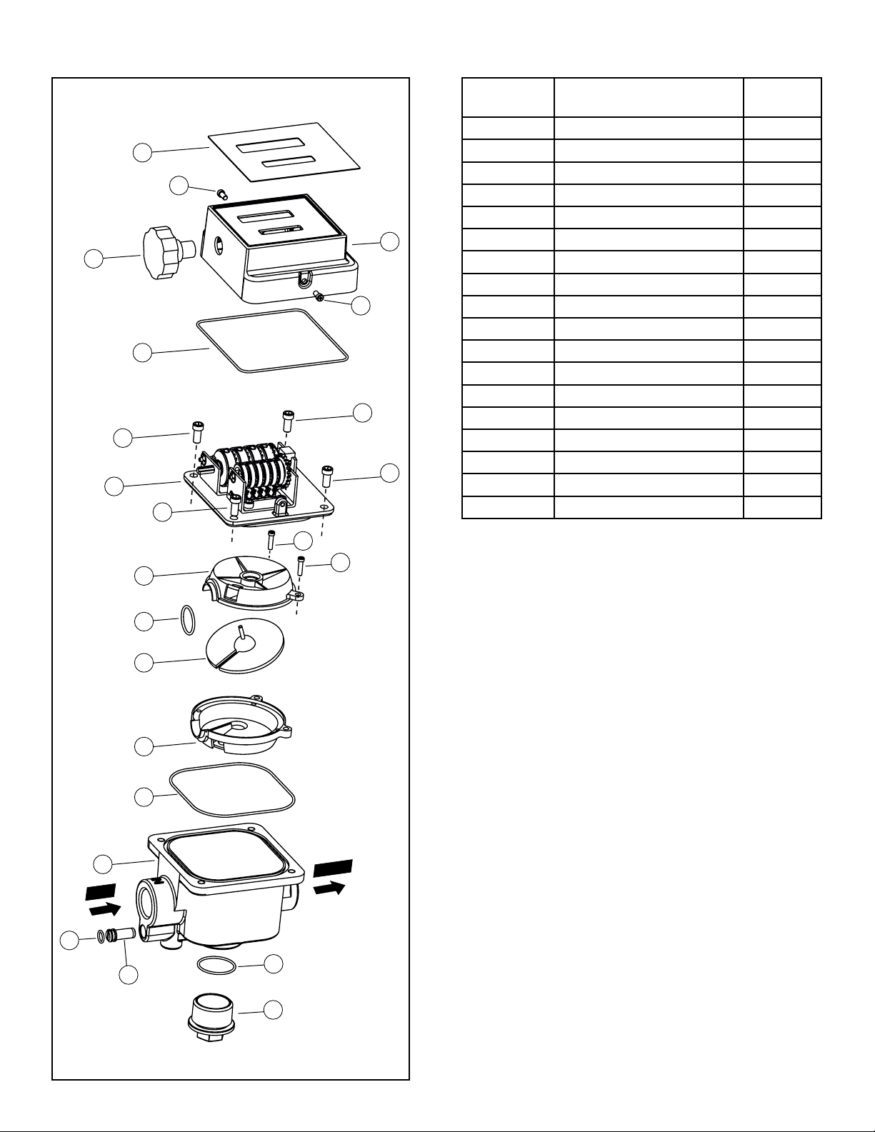
• If the Meter Value is higher than Container Value (i.e the meter is running fast), loosen the Calibration screw (16) anticlockwise.
• If the Meter Value is lower than the Container Value (i.e the meter is running slow), tighten the Calibration screw (16) clockwise.
6. Repeat steps (3 - 5) until accuracy is satisfactory.
Note
Do not reduce the flow in order to reach a preset value of the calibration container.
The right method is to start and stop the full flow repeatedly until the required level is obtained.
Notes
• Longer pipes or nozzles reduce the flow by causing higher pressure losses.
• Use By Gravity is not recommended where the height of fuel is lower than 4 feet as the flow rate will be reduced, resulting
in inaccurate measurement. For better accuracy, ensure that the flow rate never falls below 20 LPM (5 GPM).
• On field calibration is always recommended in case of Gravity installations.
Note
Always fix the
Calibration Screw (16)
with O Ring (15) to
avoid leakage.
The meter is pre-calibrated in factory under standard conditions.
A new calibration is necessary whenever there is a change in any
of the following:
• Media Viscosity OR
• Flow Rate OR
• Operating Temperature
METER CALIBRATION (Refer to Exploded View - Page 5 )
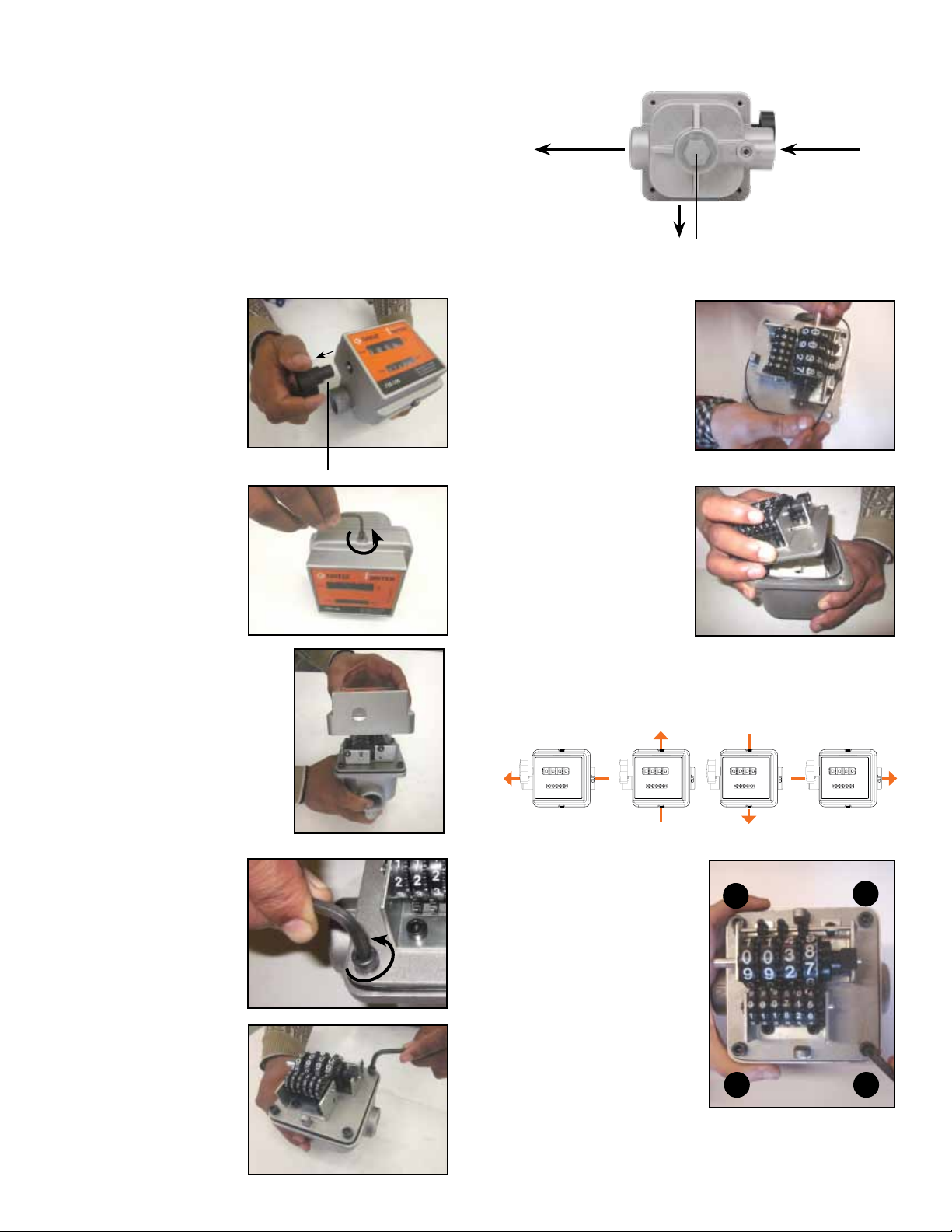
After installation, turn the reset knob (2) until the batch total becomes zero. The totalizer cannot be reset in any way.
Use by Gravity
This meter can also be used without pump pressure in a system where flow is generated due to difference in height between fuel level and
dispensing point.
Notes
• The meter can be easily disassembled into its main parts without removing the meter from the pipes.
• Never remove meter label from the meter.
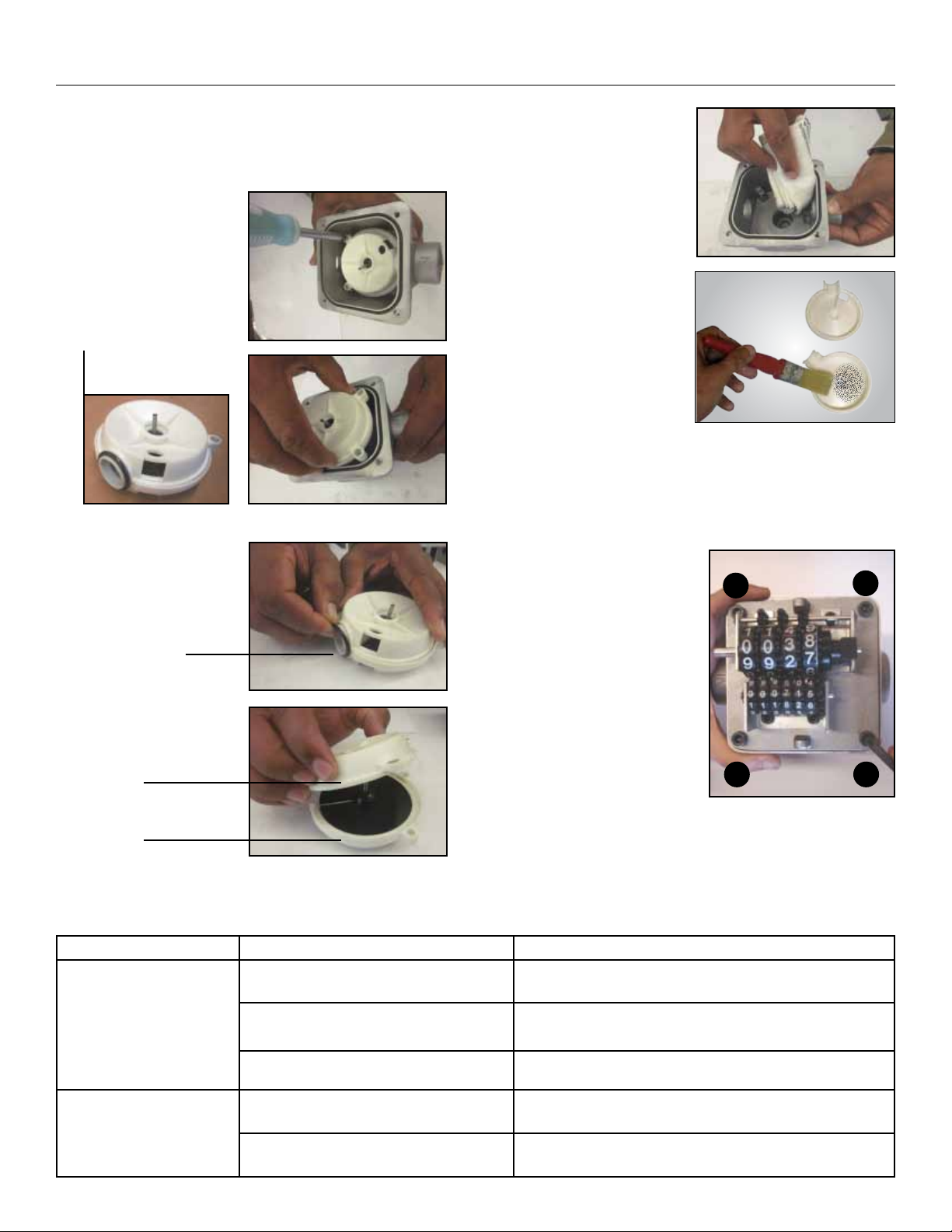
• Internal parts should be cleaned with a soft brush or small tool (i.e. a screwdriver).
• During cleaning, be careful not to damage the measuring chamber or nutating disk.
• A new calibration is always necessary after disassembling the measuring chamber. Before disassembling always ensure
that the line pressure is released and all fluid is drained from the meter.
Container Value
Meter Value
OPERATION (Refer to Exploded View - Page 5)
MAINTENANCE (Refer to Exploded View - Page 5)
This fuel meter does not require any special maintenance other than the cleaning of measuring chamber (It may get clogged sometimes due to
insufficient filtration).
98
0 2 2 2 2 2
0 0
Important
For ensuring the accuracy of measurements, the flow
rate should never be kept below 20 LPM (5 GPM).

4
• Lubricate the Seal (14) and O ring (10) with
small amount of grease before installation.
• First, tighten the four
Allen bolts (6) by
hand in an even &
diagonal pattern as
shown in the picture
& finally tighten them
with allen key (size 4).
• Recalibrate the meter as mentioned in the section:
“METER CALIBRATION”- on Page 3.
CLEANING THE MEASURING CHAMBER (Refer to Exploded View - Page 5)
PROBLEM POSSIBLE CAUSE CORRECTIVE SOLUTION
Insufficient accuracy
Wrong calibration Recalibrate the meter as shown in section “METER CALIBRA-
TION” - on Page 3
Soiled or blocked measuring chamber Clean the measuring chamber as mentioned in section
“CLEANING THE MEASURING CHAMBER”- on Page 4
Air in the fluid Locate and eliminate leaks in inlet lines
Reduced flowrate
Clogged measuring chamber Clean the measuring chamber as mentioned in section
“CLEANING THE MEASURING CHAMBER”- on Page 4
Blocked or soiled filter Clean the filter
TROUBLESHOOTING
1. Remove the knob (2), Meter cover (4) & Counter Assembly
(7) by following steps 1 - 5 from the section: “How to rotate
the display”- on Page 2.
2. Unscrew the two screws
(8) with a Phillips
Screwdriver and remove
Nutating Disc Assembly.
3. Remove O Ring (10) and
disconnect Upper Cham-
ber (9), Lower Chamber
(12) & Nutating Disk (11).
Nutating
Disc Assembly
O Ring
Upper Chamber
Lower Chamber
4. Use a soft brush to clean
the Measuring Chamber
(14). Be careful not
to damage the plastic
components.
5. To reassemble, reverse the abovementioned procedure pay-
ing particular attention to:
13
24
NOTE
After installation,
rotate the Total
gears with fingers &
ensure their smooth
movement.

5
EXPLODED VIEW COMPONENT LIST
INLET
OUTLET
1
2
2
3
5
6
7
6
6
6
4
8
8
9
11
12
13
10
14
15
16 17
18
REFERENCE
NUMBER
DESCRIPTION QUANTITY
1 Meter Label 1
2 Allen Bolts 2
3 Reset Knob 1
4 Meter Cover 1
5 Cover Seal 1
6 Allen Bolts 4
7 Counter Assembly 1
8 Screw 2
9 Upper Chamber 1
10 O Ring 1
11 Nutating Disk 1
12 Lower Chamber 1
13 Housing seal 1
14 Measuring Chamber 1
15 O Ring 1
16 Calibration Screw 1
17 O Ring 1
18 Bottom Plug 1

6
SPECIFICATIONS
Meter Type Mechanical
Mechanism Nutating Disk
Inlet / Outlet Position In-Line or Right Angle
Inlet / Outlet 3/4" (F) or 1” (F)
Threads BSP or NPT
Flow Rate* 15 to 75 LPM (4 to 20 GPM)
Accuracy +/- 1%
Repeatability +/- 1%
Max. Working Pressure 50 PSI (3.5 BAR)
Burst Pressure 435 PSI (30 BAR)
Pressure Drop 3 PSI (0.2 BAR)
Working Temperature range -10°C to 65°C (14°F to 150°F)
Max. Resettable Batch Total 9999 Litres or 999.9 Gallons
Max. Non Resettable Totalizer 999999 Litres or 99999.9 Gallons
Least Count / Resolution 0.10 Litres or 0.10 Gallons
Filter/ Screen Included No
Max. Viscosity of Media 2000 cSt
Option to Recalibrate by User Yes
Nr. Of positions in which display can be rotated 4
Protective Shroud on Meter No
Weights & Measures Approved No
Calibration Certificate Included No
Water Resistance Protection by meter label
For use with Electric Fuel Pumps Yes
For use with Gravity Flow Yes (minimum 4' head required)
* For better accuracy, the flow rate should not be allowed to fall below 20 LPM (5 GPM)
If solid particles enter the measuring chamber the correct
working of the nutating disk may be affected. Always filter the
fluid by installing a filter on the meter inlet.
RECOMMENDED USE
Diesel, Gasoline, Biodiesel, Low to medium viscosity oils
DO NOT USE WITH
Water based media etc.
Groz Engineering Tools (P) Ltd.
Groz Net Industries
Village Kherki Daula, National Highway-8
Gurgaon-122001, Haryana, INDIA
TEL +91.124.282.7700 / 221.4050
FAX +91.124.2827986 / 221.4224
FAX (USA) +1.509.271.7848
FAX (UK) +44.870.121.1854
E-MAIL [email protected]
URL www.groz-tools.com
The Groz name, Groz logo and the mark are
trademarks of Groz Engineering Tools (P) Ltd. India
WETTED COMPONENTS
Aluminium, Poly Butyl Terephthalate (PBT), Viton, Steel
Table of contents
Other Groz Measuring Instrument manuals
Popular Measuring Instrument manuals by other brands

Emerson
Emerson FB1100 instruction manual

Rice Lake
Rice Lake Non-NTEP SENDit Kit installation manual

EIJKELKAMP
EIJKELKAMP Scuba user manual

Blue-White
Blue-White ProSeries Sonic-Pro S1 Installation and operating manual

Endress+Hauser
Endress+Hauser Liquiline System CA80NO operating instructions

Emerson
Emerson FloBoss 103 instruction manual