Grundfos DPI User manual

GRUNDFOS INSTRUCTIONS
DPI
Grundfos differential pressure sensor
Installation and operating instructions

2

Table of contents
3
DPI
Grundfos differential pressure sensor
English (GB)
Installation and operating instructions . . . . . . . . . . . . . . . . . . . . . . . . . . . . . . . . 4
Čeština (CZ)
Montážní a provozní návod . . . . . . . . . . . . . . . . . . . . . . . . . . . . . . . . . . . . . . . 14
Deutsch (DE)
Montage- und Betriebsanleitung . . . . . . . . . . . . . . . . . . . . . . . . . . . . . . . . . . . 23
Dansk (DK)
Monterings- og driftsinstruktion . . . . . . . . . . . . . . . . . . . . . . . . . . . . . . . . . . . . 32
Español (ES)
Instrucciones de instalación y funcionamiento . . . . . . . . . . . . . . . . . . . . . . . . 41
Français (FR)
Notice d'installation et de fonctionnement. . . . . . . . . . . . . . . . . . . . . . . . . . . . 50
Ελληνικά (GR)
Οδηγίες εγκατάστασης και λειτουργίας . . . . . . . . . . . . . . . . . . . . . . . . . . . . . . 59
Magyar (HU)
Telepítési és üzemeltetési utasítás . . . . . . . . . . . . . . . . . . . . . . . . . . . . . . . . . 68
Italiano (IT)
Istruzioni di installazione e funzionamento . . . . . . . . . . . . . . . . . . . . . . . . . . . 77
Polski (PL)
Instrukcja montażu i eksploatacji. . . . . . . . . . . . . . . . . . . . . . . . . . . . . . . . . . . 86
Русский (RU)
Паспорт, Руководство по монтажу иэксплуатации . . . . . . . . . . . . . . . . . . 97
Declaration of conformity. . . . . . . . . . . . . . . . . . . . . . . . . . . . . . . . . . . . . . . . .108

English (GB)
4
English (GB) Installation and operating instructions
Original installation and operating instructions
CONTENTS
Page
1. Symbols used in this document 4
2. Delivery and handling 5
2.1 Delivery 5
2.2 Handling 5
3. Applications 5
4. Identification 6
4.1 Nameplate 6
5. Function 7
6. Installation 8
6.1 Extension of cable 9
6.2 Connection of amplifier 11
7. Technical data 12
7.1 Electrical data 12
7.2 Temperatures 12
7.3 Miscellaneous 12
8. Service 12
9. Disposal 12
10. Conversion tables 13
1. Symbols used in this document
Warning
Prior to installation, read these installation and operating
instructions. Installation and operation must comply with local
regulations and accepted codes of good practice.
Warning
If these safety instructions are not observed, it may result in
personal injury!
Caution
If these safety instructions are not observed, it may result in
malfunction or damage to the equipment!
Note
Notes or instructions that make the job easier and ensure safe
operation.

English (GB)
5
2. Delivery and handling
2.1 Delivery
Grundfos differential pressure sensor, type DPI, is supplied for direct
mounting with 7/16"-20 UNF connection. Miscellaneous accessories are
available on request.
2.2 Handling
Comply with local regulations and good practice for the handling of electronic
equipment.
3. Applications
Grundfos differential pressure sensor, type DPI, is used for measuring
differential pressure.
Caution
If the sensor is used in a manner not specified by the
manufacturer, the protection provided may be damaged.
Do not use Grundfos DPI sensors in explosive environments zone-
classified according to ATEX.

English (GB)
6
4. Identification
4.1 Nameplate
Fig. 1 Nameplate for DPI
Conversion of SI units into US units, see page 13.
TM03 3063 2206
Pos. Description
1 Pressure range
2 Output signal
3 Supply voltage
4 Temperature range of medium
5 Enclosure class
6 Max. differential pressure, P1 ->P2
7 Max. differential pressure, P2 ->P1
8 Max. system pressure
9 Connection P1, high pressure (discharge side)
10 Connection P2, low pressure (suction side)
11 12 - 30 V supply voltage
12 GND (earth lead)
13 Signal lead
14 Max. current consumption
15 Country of origin
16 Version no.
P2
P1
GRUNDFOS DIRECT SENSORS DPI
P: 0... +XX bar
IN 12-30 VDC, 37mA
OUT 4-20 mA
Psyst. max: 16 bar
Temp. -10 +70°C
P1-P2 max. 16 bar
P2-P1 max. 10 bar
96XXXXXX - xx - XXXX - xxxxx
IP55V-No: xx
LOW
HIGH
TM
Brown : +
Yellow : -
Green : out
10 3
1
8
4
6
7
916 12
5
11 13
14
152
US
C
DK

English (GB)
7
5. Function
The sensor measures the differential pressure between the high pressure
(P1) and the low pressure (P2). It may for example be the differential
pressure between the flanges on the suction and discharge side of a pump.
Fig. 2 DPI with position of P1 and P2
Connect the sensor to the pressure gauge tappings of the pump flanges or to
other measuring points in the system by means of 7/16"-20 UNF copper
capillary tubes.
The pressure measurement is carried out by a silicon chip covered with a
special coating developed by Grundfos.
The sensor signal is sent to an external controller or to a motor controller.
The sensor is supplied with power from an external voltage supply or direct
from the terminal box of the motor.
TM03 2058 3505
P2
P1

English (GB)
8
6. Installation
The sensor can be mounted direct on the side of the pump or on a wall by
means of the mounting bracket supplied.
Fig. 3 Connections of the DPI
The DPI cable has four leads:
TM03 2225 3905
1 12 - 30 V supply voltage Brown
2 GND (earth lead) Yellow
3 Signal lead Green
4Test lead (can be cut off during mounting). This
lead must not be connected to voltage supply. White
The DPI must be supplied with power via a PELV supply
(EN 60335-1) where GND is connected to protective earthing.
Furthermore, connect the mounting bracket and/or one or both
of the capillary tubes to earth.

English (GB)
9
6.1 Extension of cable
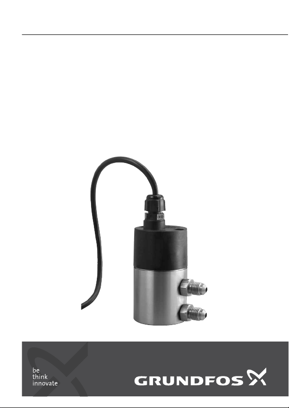
The DPI kit 2 enables the extension of the sensor cable to up to > 30 m.
If extension of the cable is required, always follow the guidelines below to
ensure optimum connection between sensor and controller. The six steps
below refer to fig. 4on page 10:
1. Remove the outer insulation 50 mm from each cable end. Pull the outer
screen away from the cable ends.
Shorten and strip the individual conductors as shown.
2. Cut 1 10 shrink-on sleeve and 4 3 shrink-on sleeves in lengths of
20 mm.
3. Place the shrink-on sleeves as shown in fig. 4. Solder together conductor
ends of the same colour.
4. Place the small shrink-on sleeves over the centre of each solder. Heat up
the shrink-on sleeves from the centre and outwards using a heat gun in
order to achieve the best result.
5. Hold the conductors close together and pull the outer screens over the
joint, one screen at a time.
6. Place the big shrink-on sleeve over the centre of the joint and shrink it
using the heat gun from the centre and outwards.

English (GB)
10
Fig. 4 How to join the cables
TM04 0571 0808
1.
2.
3.
4.
5.
6.
1 x 10 x 20 mm
4 x 3 x 20 mm
5
1120
50
All dimensions in mm

English (GB)
11
6.2 Connection of amplifier
If the cable is more than 30 m long, use an amplifier to ensure correct signal
values.
Connect the amplifier according to the diagram below:
Fig. 5 Wiring diagram for amplifier
TM04 0570 0808
230 VAC
Output
Sensor input
mA
Brown
Yellow
Green
Screen
Cable to the controller
DPI sensor cable

English (GB)
12
7. Technical data
7.1 Electrical data
7.2 Temperatures
7.3 Miscellaneous
Conversion of SI units into US units, see page 13.
8. Service
If the sensor is defective, replace the sensor.
9. Disposal
This product or parts of it must be disposed of in an environmentally sound
way:
1. Use the public or private waste collection service.
2. If this is not possible, contact the nearest Grundfos company or service
workshop.
Voltage supply to the sensor:
PELV (protective extra low voltage)
(EN 60335-1)
12 - 30 VDC
Load: 24 V: max. 500 ohm
16 V: max. 200 ohm
12 V: max. 100 ohm
Output signal, 3-wire: 4 - 20 mA
Enclosure class: IP 55 (according to EN 60529)
Temperature at sensor: –10 °C to +70 °C
temporarily (max. 10 min.) up to 80 °C
Ambient temperature: –10 °C to +70 °C
Storage temperature: –40 °C to +80 °C
Cable length: 0.9 m
Cable length for DPI kit 2: 5 m
Max. air humidity: 95 %
Pressure range DPI: 0.... 0.6, 1.0, 1.6, 2.5, 4.0, 6.0, 10 bar
Pressure range DPI kit 2: 0.... 1.2, 2.5, 4.0, 6.0, 10 bar

English (GB)
13
10. Conversion tables
Pressure
Temperature
SI unit [bar] US unit [psi]
0.6 8.7
1 14.5
1.6 23.2
2.5 36.3
458
687
10 145
16 232
SI unit [ °C] US unit [°F]
–10 14
032
10 50
20 68
30 86
40 104
50 122
60 140
70 158
80 176
Subject to alterations.

Čeština (CZ)
14
Čeština (CZ) Montážní a provozní návod
OBSAH
Strana
1. Označení důležitosti pokynů14
2. Dodávka a manipulace 15
2.1 Dodávka 15
2.2 Manipulace 15
3. Oblasti použití 15
4. Identifikace 16
4.1 Typový štítek 16
5. Funkce 17
6. Instalace 18
6.1 Prodloužení kabelu 19
6.2 Připojení zesilovače21
7. Technická údaje 22
7.1 Elektrické údaje 22
7.2 Teploty 22
7.3 Různé 22
8. Servis 22
9. Likvidace výrobku 22
1. Označení důležitosti pokynů
Varování
Před zahájením montážních prací si pečlivěpřečtěte tyto montážní
a provozní předpisy. Montáž a provoz provádějte rovněž v souladu
s místními předpisy a se zavedenou osvědčenou praxí.
Varování
Bezpečnostní pokyny uvedené v tomto montážním a provozním
návodu, jejichž nedodržení může způsobit ohrožení osob.
Pozor
Tento symbol je uveden u bezpečnostních pokynů, jejichž
nedodržení může mít za následek ohrožení zařízení a jeho funkcí.
Pokyn
Pod tímto symbolem jsou uvedeny rady a pokyny, které usnadňují
práci a které zajišt’ují bezpečný provoz čerpadla.

Čeština (CZ)
15
2. Dodávka a manipulace
2.1 Dodávka
Snímačdiferenčního tlaku typu Grundfos DPI se dodává včetněpřípojky
7/16"-20 UNF ve stavu vhodném pro přímou montáž. Na objednávku
můžeme ke snímači dodat různé příslušenství.
2.2 Manipulace
Při manipulaci se snímačem dodržujte příslušné místní předpisy a zásady
zavedené praxe pro elektronická zařízení.
3. Oblasti použití
Snímačdiferenčního tlaku Grundfos typu DPI je určen k měření diferenčního
tlaku.
Pozor
Jestliže je snímačpoužíván jinak, než je předepsáno výrobcem,
může se stát, že se ochrana poškodí.
Nepoužívejte snímače Grundfos DPI v prostředích s nebezpečím
výbuchu v zónách klasifikovaných dle ATEX.

Čeština (CZ)
16
4. Identifikace
4.1 Typový štítek
Obr. 1 Typový štítek snímače DPI
TM03 3063 2206
Pol. Název
1 Tlakový rozsah
2 Výstupní signál
3 Napájecí napětí
4 Teplotní rozsah média
5Třída krytí
6 Maximální diferenční tlak, P1 -> P2
7 Maximální diferenční tlak, P2 -> P1
8 Maximální tlak v soustavě
9Přípojka P1, vysoký tlak (výtlačná strana)
10 Přípojka P2, nízký tlak (sací strana)
11 Napájecí napětí 12 - 30 V
12 GND (zemnicí vodič)
13 Signální vodič
14 Max. spotřeba proudu
15 Zeměpůvodu
16 Verze číslo
P2
P1
GRUNDFOS DIRECT SENSORS DPI
P: 0... +XX bar
IN 12-30 VDC, 37mA
OUT 4-20 mA
Psyst. max: 16 bar
Temp. -10 +70°C
P1-P2 max. 16 bar
P2-P1 max. 10 bar
96XXXXXX - xx - XXXX - xxxxx
IP55V-No: xx
LOW
HIGH
TM
Brown : +
Yellow : -
Green : out
10 3
1
8
4
6
7
916 12
5
11 13
14
152
US
C
DK

Čeština (CZ)
17
5. Funkce
Snímačměří diferenční tlak mezi místem vysokého tlaku (P1) a místem
nízkého tlaku (P2). Může se jednat např. o měření diferenčního tlaku mezi
přírubami na sací a výtlačné straněčerpadla.
Obr. 2 SnímačDPI a poloha přípojek P1 a P2
Pomocí měděných kapilárních přípojek 7/16"-20 UNF připojte snímačk
manometrovým přípojkám na přírubách čerpadla nebo jej napojte na jiné
měřicí body dané soustavy.
Měření tlaku se děje prostřednictvím křemíkového integrovaného obvodu
(čipu), krytého speciálním povlakem vyvinutým v Grundfosu.
Signál od snímače přichází do externí řídící jednotky nebo do řídící jednotky
motoru.
Snímačje napájen ze samostatného zdroje napájecího napětí nebo přímo ze
svorkovnice motoru.
TM03 2058 3505
P2
P1

Čeština (CZ)
18
6. Instalace
Snímačinstalujte přímo po straněčerpadla nebo na stěnu s použitím
montážní konzoly.
Obr. 3 Přípojky snímače DPI
Kabel snímače DPI má čtyři vodiče:
TM03 2225 3905
1 Napájecí napětí 12 - 30 V hnědý
2 GND (zemnicí vodič) žlutý
3 signální vodič(zelený)
4Zkušební vodič(při montáži možno odstřihnout)
Tento vodičnesmí být připojen na napájecí napětí. bílý
SnímačDPI musí být napájen ze zdroje ochranného malého
napětí (PELV) (EN 60335-1), přičemž zemnicí vodič(GND) musí
být připojen k systému ochranného zemnění. Dále je k zemnicí
soustavětřeba připojit montážní konzolu, popř. jednu nebo obě
kapilární přípojky snímače.

Čeština (CZ)
19
6.1 Prodloužení kabelu
DPI souprava 2 umožňuje prodloužení kabelu snímače až do > 30 m.
Jestliže je požadováno prodloužení kabelu, vždy uposlechněte pokynů
uvedených níže k zajištění optimálního spojení mezi snímačem a řídící
jednotkou. Šest krokůse týká obr. 4na straně20:
1. Odstraňte vnější izolaci 50 mm z každého konce kabelu. Stáhněte vnější
stínění z koncůkabelů.
Zkrat’te a stáhněte izolaci jednotlivých vodičů, jak je ukázáno.
2. Nastříhejte 1 smršt’ovací trubičku 10 a 4 smršt’ovací trubičky 3 na
délky 20 mm.
3. Umístěte smršt’ovací trubičky, jak je ukázáno na obr. 4. Spájejte spolu
konce vodičů stejné barvy.
4. Umístěte malé smrštovací trubičky na střed každého pájeného spoje.
Zahřejte smršt’ovací trubičky ze středu a z vnější strany pomocí
teplovzdušné pistole pro dosažení co nejlepšího výsledku.
5. Podržte vodiče blízko u sebe a natáhněte vnější stínění přes spojená
místa jedno po druhém.
6. Umístěte větší smrštovací trubičku na střed každého pájeného spoje a
smrštěte ji použitím teplovzdušné pistole od středu po okraj.

Čeština (CZ)
20
Obr. 4 Jak spojit kabely
TM04 0571 0808
1.
2.
3.
4.
5.
6.
1 x 10 x 20 mm
4 x 3 x 20 mm
5
10
10 20
50
Všechny rozměry jsou v mm
Other manuals for DPI
1
Table of contents
Languages:
Other Grundfos Accessories manuals

Grundfos
Grundfos WIO sensor User manual

Grundfos
Grundfos LiqTec User manual

Grundfos
Grundfos DPI User manual

Grundfos
Grundfos LiqTec User manual

Grundfos
Grundfos MAGNA3 25-100 (N) User manual

Grundfos
Grundfos WIO sensor User manual

Grundfos
Grundfos Pt100 User manual

Grundfos
Grundfos Terminator User manual

Grundfos
Grundfos Pt100 User manual

Grundfos
Grundfos LiqTec User manual