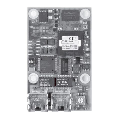
Grundfos CIM 060 User manual

CIM 060
Installation and operating instructions
GRUNDFOS INSTRUCTIONS

2

3
Table of contents
CIM 060
English (GB)
Installation and operating instructions. . . . . . . . . . . . . . . . . . . . . . . . . . . . . . . . . 4
Deutsch (DE)
Montage- und Betriebsanleitung . . . . . . . . . . . . . . . . . . . . . . . . . . . . . . . . . . . . 10
Dansk (DK)
Monterings- og driftsinstruktion. . . . . . . . . . . . . . . . . . . . . . . . . . . . . . . . . . . . . 16
Français (FR)
Notice d'installation et de fonctionnement. . . . . . . . . . . . . . . . . . . . . . . . . . . . . 22
(RU)
, . . . . . . . . . . . . . . . . . . . 28
Declaration of conformity . . . . . . . . . . . . . . . . . . . . . . . . . . . . . . . . . . . . . . . . . 34
Declaration of conformity RU . . . . . . . . . . . . . . . . . . . . . . . . . . . . . . . . . . . . . . 36

English (GB)
4
English (GB) Installation and operating instructions
Original installation and operating instructions
CONTENTS
Page
1. Symbols used in this document
2. Abbreviations
3. Product description
3.1 Introduction
The CIM 060 is an add-on module which you can
instal in a CIU 902 SEG AUTOADAPT communication
unit or a CU 362 Dedicated Controls system to
enable radio communication with the Grundfos GO.
The on-board antenna enables connection to
Grundfos GO within a 10 meters radius. You can fit
an external antenna for a larger communication
range.
You can establish connection via a button on the
module or via a configurable connection code.
1. Symbols used in this document 4
2. Abbreviations 4
3. Product description 4
3.1 Introduction 4
3.2 Product overview 5
3.3 LED 5
4. Installation 6
4.1 Fitting the CIM 060 into a CIU 902 box 6
4.2 Fitting the CIM 060 into a CU 362 7
5. Connecting Grundfos GO 7
5.1 Via the connection button 7
5.2 Via a connection code 8
6. Fault finding 9
7. Technical data 9
8. Disposal 9
Warning
Prior to installation, read these installation
and operating instructions. Installation and
operation must comply with local
regulations and accepted codes of good
practice.
Warning
If these safety instructions are not
observed, it may result in personal injury.
Warning
If these instructions are not observed, it
may lead to electric shock with consequent
risk of serious personal injury or death.
Caution
If these safety instructions are not
observed, it may result in malfunction or
damage to the equipment.
Note
Notes or instructions that make the job
easier and ensure safe operation.
CIM Communication interface module
CIU Communication interface unit
CU Control unit
GND Earth connection
GSM Global system for mobile
communications
LED Light-emitting diode
SEG Sewage grinder pump
SELV Separated or safety extra-low voltage
SELV-E Separated or safety extra-low voltage
with earth
SMA Subminiature version A
TTL Transistor to transistor logic

English (GB)
5
3.2 Product overview
Fig. 1 CIM 060
3.3 LED
See also installation and operating instructions of the
Grundfos GO.
TM06 2190 3714
Pos. Description
1 Mounting holes
2Connecting plug for the product
(visible on the back of the CIM 060)
3 Connection button
4LED
5 On-board antenna
6 Connector for external SMA antenna
4
5
2
6
1
3
1
Indicator Description
Light off
The module receives data from the
product but is not connected to any
Grundfos GO system.
Power is off.
Short
green
flashes
The product in question is highlighted
in the Grundfos GO display and the
wink button has been pressed.
The LED flashes to inform the user of
the location of the highlighted pump.
Longgreen
flashes
The product in question is selected in
the Grundfos GO menu.
The module is prompting the user to
press the connection button in order
to connect to Grundfos GO.
Permanent
ly green
The product is connected to
Grundfos GO. The indicator light is
on as long as the product is selected
in Grundfos GO.
Red
flashes
Error/no connection available.
The power has for example just been
switched on and the module is
waiting to receive data from the
product. It ceases flashing when the
module is ready for connection.

English (GB)
6
4. Installation 4.1 Fitting the CIM 060 into a CIU 902 box
• Click the CIM 060 on the top right corner of the
CIU box. See fig. 2
Fig. 2 Position of the CIM 060 in a CIU 902
If the product is to be connected to a GSM network,
connect the CIU 902 to a CIU 250 unit via GENIbus.
See fig. 3.
Fig. 3 CIM 060 in a CIU 902 connected to a
GSM network
Warning
The module must only be connected to
SELV or SELV-E circuits.
Warning
Switch off the power supply to the CIU 902
or CU 362 before fitting the CIM module.
Warning
Avoid electrostatic discharge (ESD) when
fitting the CIM module, for instance by
using an ESD protection kit, product
number 96884939.
Note
The CIM module must be installed by
authorised staff.
Note
When installed in a metal cabinet, it might
be necessary to fit an external antenna on
the module.
TM06 2482 4314TM06 2471 4214
Caution
Do not fit the CIM 250 in the CIU 902.
CIM
060
CIU 902
CIU 902
CIU 250
GENIbus
CIM
060
CIM
250

English (GB)
7
4.2 Fitting the CIM 060 into a CU 362
• Remove the back cover of the CU 362.
• Click the CIM 060 on top of the main board, in the
back of the CU 362. See fig. 4.
• Fit the screw in the bottom mounting hole.
• Use cutting pliers to cut out the back cover of the
CU 362, around the external antenna connector.
See fig. 1, pos. 6.
See also section installation and operating
instructions of the CU 362.
Fig. 4 Fitting the CIM 060 in the CU 362
If the product is to be connected to a GSM network,
connect the CU 362 to a CIU 250 unit in this way:
• Install a CIM 040 in the CIU 250 box next to the
CIM 250.
• Connect the CIM 040 to the TTL service port of
CU 362 via the TTL cable provided with the
CIM 040. See fig. 5.
Fig. 5 CIM 060 in a CU 362 connected to a
GSM network
5. Connecting Grundfos GO
See also installation and operating instructions of the
Grundfos GO.
5.1 Via the connection button
1. Select [Connect] in the main menu, under
[Remote]. See fig. 6, pos. 1.
2. Press [List].
3. Select the product hosting the CIM 060. It may be
necessary to press the wink button to identify the
product. See section 3.3 LED.
4. Press the connection button on the module
(within 30 seconds). The LED is now
permanently green and the CIM 060 is connected
to Grundfos GO.
Alternatively, if the product is the only one in range,
press [Connect] instead of [List], and skip step 3.
Fig. 6 Main menu in Grundfos GO
TM06 2500 4314TM06 2467 4214
CIU 250 CU 362
CIM
250
CIM
040
CIM
060
TTL cable
TM06 2343 4014
2
1

English (GB)
8
5.2 Via a connection code
You can setup a connection code to avoid having to
press the connection button each time and to restrict
remote access to the product.
5.2.1 Setting the code in the product
1. Connect Grundfos GO to the product via the
connection button. See section 5. Connecting
Grundfos GO.
2. In the product dashboard, select [Settings].
See fig. 7.
3. Choose [Connection code].
4. Enter the wanted code and press [OK].
The code must be a character string (ASCII).
The code can always be modified. The old code is
not needed.
Fig. 7 Product dashboard in Grundfos GO
5.2.2 Setting the code in Grundfos GO
You can define a default connection code in
Grundfos GO so that it automatically attempts to
connect to the selected product via this code.
When a product with the same connection code is
selected in Grundfos GO, the Grundfos GO
automatically connects to the product without having
to press the connection button on the module.
Define the default code in Grundfos GO in this way:
1. In the main menu, under [General], select
[Settings]. See fig. 6, pos. 2.
2. Choose [Remote].
3. Enter the connection code in the field "Preset
connection code". The field now says
"Connection code set". See fig. 8.
You can always modify the default connection code
by pressing [Delete] and entering a new one.
If Grundfos GO fails to connect and ask for pressing
the connection button on the product, it means that
the product has no connection code or has a
different connection code. In this case, you can only
establish connection via the connection button.
Fig. 8 Presetting the connection code in
Grundfos GO
Note
After setting a connection code, you must
switch off the product for five seconds
before you can use the new connection
code.
TM06 2345 4014
TM06 2585 4414

English (GB)
9
6. Fault finding
See also installation and operating instructions of the
product in question and of the Grundfos GO.
The above manuals can be found in the Grundfos
Product Center: product-selection.grundfos.com
7. Technical data
8. Disposal
This product or parts of it must be disposed of in an
environmentally sound way:
1. Use the public or private waste collection service.
2. If this is not possible, contact the nearest
Grundfos company or service workshop.
Subject to alterations.
Fault Possible cause Remedy
1. The connection
between the Grundfos
GO and the CIM 060
has failed.
a) Power is off. Turn power on. Wait until the LED ceases
to flash.
b) The product has no connection
code or has a different
connection code.
Connect via the connection button on the
module. See 5.1 Via the connection
button.
c) The connection time has
elapsed (30 seconds).
Reselect the product in Grundfos GO.
Note: If the connection button has not
been pressed within 30 seconds from the
time the product was selected in
Grundfos GO, the connection is
cancelled.
The CIM 060 is defective. Replace the CIM 060.
2. No internal
communication
between the CIM 060
and the product. (LED
flashing red).
a) The CIM 060 is not fitted
correctly on the product. Check that the module is fitted correctly.
b) The connecting plug on the
CIM 060 is defective.
Check the connecting plug on the
CIM 060 (one of the pins might be
damaged).
c) The connecting plug on the
product is defective.
Check the connecting plug on the
product.
Communication range
of on-board antenna 10 m
Storage temperature -20 to 85 °C
Operating temperature -20 to 85 °C
Operating and storage
humidity
0-95 % RH
Non-condensing
External antenna
2.4 GHz RF signal
SMA connector
Max. cable length 2.9 m

Deutsch (DE)
10
Deutsch (DE) Montage- und Betriebsanleitung
Übersetzung des englischen Originaldokuments
INHALTSVERZEICHNIS
Seite
1. Verwendete Symbole
2. Abkürzungen
3. Produktbeschreibung
3.1 Allgemeines
Das CIM 060 ist ein Erweiterungsmodul, das Sie in
eine Kommunikationseinheit vom Typ CIU 902
SEG AUTOADAPT oder in ein entsprechendes Regel-
system vom Typ CU 362 einbauen können, um eine
Funkkommunikation mit dem Grundfos GO zu
ermöglichen.
Mithilfe der integrierten Antenne kann in einem
Radius von zehn Metern eine Verbindung zum
Grundfos GO hergestellt werden. Um den größeren
Kommunikationsradius zu vergrößern, können Sie
eine externe Antenne anbringen.
Die Verbindung können Sie über eine Taste auf dem
Modul oder über einen konfigurierbaren Sicherheits-
schlüssel herstellen.
1. Verwendete Symbole 10
2. Abkürzungen 10
3. Produktbeschreibung 10
3.1 Allgemeines 10
3.2 Produktübersicht 11
3.3 Leuchtdiode 11
4. Installation 12
4.1 Einbau des CIM 060 in einen CIU 902-
Kasten 12
4.2 Einbau des CIM 060 in ein CIU 362 13
5. Verbinden des Grundfos GO 13
5.1 Über die Verbindungstaste 13
5.2 Über einen Sicherheitsschlüssel 14
6. Störungsübersicht 15
7. Technische Daten 15
8. Entsorgung 15
Warnung
Lesen Sie diese Montage- und Betriebsan-
leitung vor der Montage. Montage und
Betrieb müssen nach den örtlichen Vor-
schriften und den anerkannten Regeln der
Technik erfolgen.
Warnung
Die Nichtbeachtung dieser Sicherheitshin-
weise kann zu Personenschäden führen.
Warnung
Die Nichtbeachtung dieser Sicherheitshin-
weise kann zum elektrischen Schlag füh-
ren, der schwere Personenschäden oder
den Tod zur Folge haben kann.
Achtung
Die Nichtbeachtung dieser Sicherheitshin-
weise kann Fehlfunktionen oder Sach-
schäden zur Folge haben.
Hinweis
Hinweise oder Anweisungen, die die Arbeit
erleichtern und einen sicheren Betrieb
gewährleisten.
CIM Kommunikationsschnittstellenmodul
CIU Kommunikationsschnittstellengerät
CU Steuereinheit
GND Masseanschluss
GSM Globales System für eine mobile Kom-
munikation
LED Leuchtdiode
SEG Abwasserpumpe mit Schneidsystem
SELV Getrennte oder Sicherheitskleinspan-
nung
SELV-E Getrennte oder Sicherheitskleinspan-
nung mit Masse
SMA SubMiniature Version A
TTL Transistor-Transistor-Logik

Deutsch (DE)
11
3.2 Produktübersicht
Abb. 1 CIM 060
3.3 Leuchtdiode
Weitere Informationen finden Sie in der Montage-
und Betriebsanleitung des Grundfos GO.
TM06 2190 3714
Pos. Beschreibung
1 Montagebohrungen
2Anschlussstecker für das Produkt (sicht-
bar an der Rückseite des CIM 060)
3 Verbindungstaste
4LED
5 Integrierte Antenne
6 Stecker für externe SMA-Antenne
4
5
2
6
1
3
1
Meld-
eleuchte Beschreibung
Keine
Anzeige
Das Modul empfängt zwar Daten vom
Produkt, ist jedoch nicht mit einem
GO-System von Grundfos verbunden.
Stromversorgung ist abgeschaltet.
Grüne LED
blinkt
schnell
Das betreffende Produkt wird auf
dem Display des Grundfos GO her-
vorgehoben, nachdem die Blinktaste
gedrückt wurde. Die blinkende LED
zeigt dem Bediener an, wo sich die
hervorgehobene Pumpe befindet.
Grüne LED
blinkt lang-
sam
Das betreffende Produkt wird im
Menü des Grundfos GO ausgewählt.
Das Produkt fordert den Bediener
dazu auf, die Verbindungstaste zu
drücken, um eine Verbindung zum
Grundfos GO herzustellen.
Grüne LED
leuchtet
dauerhaft
Das Produkt ist mit dem Grundfos GO
verbunden. Die Meldeleuchte leuch-
tet, solange das Produkt im Grundfos
GO ausgewählt ist.
Rote LED
blinkt
Fehler/keine Verbindung verfügbar.
Zum Beispiel: Die Stromversorgung
wurde gerade erst eingeschaltet und
das Modul wartet darauf, Daten vom
Produkt zu empfangen. Wenn das
Modul dazu bereit ist, verbunden zu
werden, hört die Anzeige auf, zu blin-
ken.

Deutsch (DE)
12
4. Installation 4.1 Einbau des CIM 060 in einen CIU 902-
Kasten
• Bringen Sie das CIM 060 in der oberen rechten
Ecke des CIU-Kastens an. Siehe Abb. 2
Abb. 2 Position des CIM 060 in einem CIU 902
Wenn das Produkt mit einem GSM-Netzwerk verbun-
den werden soll, muss das CIU 902 über eine GENI-
bus-Verbindung mit einem CIU 250 verbunden wer-
den. Siehe Abb. 3.
Abb. 3 Das CIM 060 in einem CIU 902 mit
einer GSM-Netzwerkverbindung
Warnung
Das Modul darf nur an Schutzkleinspan-
nungen vom Typ SELV oder SELV-E ange-
schlossen werden.
Warnung
Schalten Sie die Stromversorgung zum
CIU 902 oder CU 362 ab, bevor Sie das
CIM-Modul montieren.
Warnung
Vermeiden Sie bei der Montage des CIM-
Moduls eine elektrostatische Entladung
(ESD), zum Beispiel durch das Verwenden
eines ESD-Schutzes (Produktnummer:
96884939).
Hinweis
Das CIM-Modul darf nur von autorisiertem
Fachpersonal installiert werden.
Hinweis
Bei einer Installation im Metallschrank
kann es erforderlich sein, eine externe
Antenne am Modul anzubringen.
TM06 2482 4314TM06 2471 4214
Achtung
Bauen Sie das CIM 250 nicht in ein
CIU 902 ein.
CIM
060
CIU 902
CIU 902
CIU 250
GENIbus
CIM
060
CIM
250

Deutsch (DE)
13
4.2 Einbau des CIM 060 in ein CIU 362
• Entfernen Sie die Rückwand des CU 362.
• Bringen Sie das CIM 060 auf der Hauptplatine an
der Rückseite des CU 362 an. Siehe Abb. 4.
• Setzen Sie eine Schraube in die untere Montage-
bohrung ein.
• Verwenden Sie eine Schneidezange, um eine
Öffnung in die Rückseite des CU 362 um den
Stecker für die externe Antenne zu schneiden.
Siehe Abb. 1, Pos. 6.
Weitere Informationen finden Sie in der Montage-
und Betriebsanleitung des CU 362.
Abb. 4 Einbau des CIM 060 in das CIU 362
Wenn das Produkt mit einem GSM-Netzwerk verbun-
den werden soll, muss das CIU 362 mit dem CIU 250
wie folgt verbunden werden:
• Installieren Sie ein CIM 040 im CIU 250-Kasten
neben dem CIM 250.
• Schließen Sie das CIM 040 an den TTL-Service-
anschluss des CU 362 an. Verwenden Sie dafür
das dem CIM 040 beiliegende TTL-Kabel.
Siehe Abb. 5.
Abb. 5 Das CIM 060 in einem CIU 362 mit
einer GSM-Netzwerkverbindung
5. Verbinden des Grundfos GO
Weitere Informationen finden Sie in der Montage-
und Betriebsanleitung des Grundfos GO.
5.1 Über die Verbindungstaste
1. Wählen Sie [Verbinden] im Hauptmenü unter
[Fernst.] aus. Siehe Abb. 6, Pos. 1.
2. Klicken Sie auf [Liste].
3. Wählen Sie das Produkt aus, in dem das
CIM 060 eingebaut ist. Eventuell müssen Sie die
Blinktaste drücken, um das Produkt bestimmen
zu können. Siehe Abschnitt 3.3 Leuchtdiode.
4. Drücken Sie die Verbindungstaste auf dem Modul
(innerhalb von 30 Sekunden). Die LED leuchtet
nun dauerhaft grün und das CIM 060 ist mit dem
Grundfos GO verbunden.
Alternativ können Sie auch auf [Verbinden] anstatt
auf [Liste] drücken und Schritt 3 auslassen, falls das
Produkt das einzige in Reichweite ist.
Abb. 6 Hauptmenü des Grundfos GO
TM06 2500 4314TM06 2467 4214
CIU 250 CU 362
CIM
250
CIM
040
CIM
060
TTL-Kabel
TM06 2343 4014
2
1

Deutsch (DE)
14
5.2 Über einen Sicherheitsschlüssel
Sie können einen Sicherheitsschlüssel (Passwort)
einrichten. Dann müssen Sie nicht bei jedem Mal die
Verbindungstaste drücken. Zudem können Sie hier-
mit den Fernzugriff auf das Produkt einschränken.
5.2.1 Den Sicherheitsschlüssel im Produkt
einrichten
1. Verbinden Sie den Grundfos GO über die Verbin-
dungstaste mit dem Produkt. Siehe Abschnitt
5. Verbinden des Grundfos GO.
2. Wählen Sie [Einstellungen] im Bedienfeld des
Produkts aus. Siehe Abb. 7.
3. Wählen Sie [Löschen] aus.
4. Geben Sie den gewünschten Sicherheitsschlüs-
sel ein und drücken Sie auf [OK].
Der Sicherheitsschlüssel (Passwort) muss eine Zei-
chenkodierung (ASCII) sein.
Der Sicherheitsschlüssel kann jederzeit geändert
werden. Das Eingeben des vorherigen Sicherheits-
schlüssel ist nicht erforderlich.
Abb. 7 Bedienfeld des Produkts im Grundfos
GO
5.2.2 Den Sicherheitsschlüssel (Passwort) im
Grundfos GO einrichten
Sie können einen Standardsicherheitsschlüssel im
Grundfos GO einrichten, sodass es automatisch eine
Verbindung über den Sicherheitsschlüssel mit dem
gewählten Produkt herstellt.
Wenn ein Produkt mit dem gleichen Sicherheits-
schlüssel im Grundfos GO ausgewählt wird, verbin-
det sich das Grundfos GO automatisch mit dem Pro-
dukt, ohne dass Sie die Verbindungstaste auf dem
Modul drücken müssen.
Sie können den Standardschlüssel im Grundfos GO
wie folgt einstellen:
1. Wählen Sie [Einstellungen] im Hauptmenü unter
[Allgemeines] aus. Siehe Abb. 6, Pos. 2.
2. Wählen Sie [Fernst.] aus.
3. Geben Sie den Sicherheitsschlüssel in das Feld
"Schlüssel vorgeben" ein. Im Feld wird nun
"Schlüssel ist vorgegeben" angezeigt. Siehe Abb.
8.
Sie können den Standardsicherheitsschlüssel jeder-
zeit ändern, indem Sie auf [Löschen] drücken und
einen neuen Code eingeben.
Wenn Grundfos GO keine Verbindung herstellen
kann und Sie dazu auffordert, die Verbindungstaste
auf dem Produkt zu drücken, ist entweder kein
Sicherheitsschlüssel vorhanden oder die Sicher-
heitsschlüssel stimmt nicht überein. In diesem Fall
können Sie nur über die Verbindungstaste eine Ver-
bindung herstellen.
Abb. 8 Den Sicherheitsschlüssel (Passwort) im
Grundfos GO vorgeben
Hinweis
Nach dem Einrichten des Sicherheits-
schlüssels müssen Sie das Produkt fünf
Sekunden lang ausschalten, bevor Sie den
neuen Sicherheitsschlüssel verwenden
können.
TM06 2345 4014
TM06 2585 4414

Deutsch (DE)
15
6. Störungsübersicht
Weitere Informationen finden Sie in der Montage-
und Betriebsanleitung des Grundfos GO bzw. des
betreffenden Produkts.
Die oben genannten Handbücher finden Sie im
Grundfos Product Center:
product-selection.grundfos.com
7. Technische Daten
8. Entsorgung
Dieses Produkt sowie Teile davon müssen umwelt-
gerecht entsorgt werden:
1. Nutzen Sie die öffentlichen oder privaten
Entsorgungsgesellschaften.
2. Ist das nicht möglich, wenden Sie sich bitte an
die nächste Grundfos Gesellschaft oder Werk-
statt.
Technische Änderungen vorbehalten.
Störung Mögliche Ursache Abhilfe
1. Es konnte keine Ver-
bindung zwischen
Grundfos GO und
CIM 060 hergestellt
werden.
a) Stromversorgung ist abge-
schaltet.
Schalten Sie die Stromversorgung ein.
Warten Sie, bis die LED aufhört, zu blin-
ken.
b) Dem Produkt wurde entweder
kein Sicherheitsschlüssel zuge-
wiesen oder die Schlüssel
stimmt nicht überein.
Stellen Sie eine Verbindung über die Ver-
bindungstaste am Modul her.
Siehe 5.1 Über die Verbindungstaste.
c) Die Verbindungszeit wurde
überschritten (30 Sekunden).
Wählen Sie das Produkt im Grundfos GO
erneut aus.
Hinweis: Wenn Sie die Verbindungstaste
nicht innerhallb von 30 Sekunden nach
dem Auswählen des Produkts im Grund-
fos GO drücken, wird der Verbindungs-
vorgang abgebrochen.
Das CIM 060 ist defekt. Ersetzen Sie das CIM 060.
2. Es besteht keine
interne Kommunika-
tion zwischen dem
CIM 060 und dem Pro-
dukt. (LED blinkt rot).
a) Das CIM 060 ist nicht richtig an
das Produkt angeschlossen.
Überprüfen Sie, ob das Modul korrekt
eingebaut ist.
b) Der Anschlussstecker am
CIM 060 ist defekt.
Überprüfen Sie den Anschlussstecker
am CIM 060 (einer der Pins ist eventuell
beschädigt).
c) Der Anschlussstecker am Pro-
dukt ist defekt.
Überprüfen Sie den Anschlussstecker
am Produkt.
Kommunikationsbe-
reich der integrierten
Antenne
10 m
Lagerungstemperatur -20 to 85 °C
Betriebstemperatur -20 to 85 °C
Luftfeuchtigkeit für
Betrieb und Lagerung
0 bis 95 % RF
nicht kondensierend
Externe Antenne
2,4 GHz HF-Signal
SMA-Buchse
Max. Kabellänge von
2,9 m

Dansk (DK)
16
Dansk (DK) Monterings- og driftsinstruktion
Oversættelse af den originale engelske udgave
INDHOLDSFORTEGNELSE
Side
1. Symboler brugt i dette dokument
2. Forkortelser
3. Produktbeskrivelse
3.1 Indledning
CIM 060 er et udvidelsesmodul som du kan installere
i en CIU 902 SEG AUTOADAPT-kommunikationsen-
hed eller et CU 362 Dedicated Controls-system for at
aktivere radiokommunikation med Grundfos GO.
Den indbyggede antenne muliggør forbindelse til
Grundfos GO inden for en radius på 10 meter.
Du kan montere en udvendig antenne for at opnå en
større rækkevidde.
Du kan etablere forbindelse via en knap på modulet
eller via en konfigurerbar sikkerhedskode.
1. Symboler brugt i dette dokument 16
2. Forkortelser 16
3. Produktbeskrivelse 16
3.1 Indledning 16
3.2 Produktoversigt 17
3.3 LED 17
4. Installation 18
4.1 Montering af CIM 060 i en CIU 902-kasse 18
4.2 Montering af CIM 060 i CU 362 19
5. Tilslutning af Grundfos GO 19
5.1 Via forbindelsesknappen 19
5.2 Via sikkerhedskode 20
6. Fejlfinding 21
7. Tekniske data 21
8. Bortskaffelse 21
Advarsel
Læs denne monterings- og driftsinstruktion
før installation. Følg lokale forskrifter og
gængs praksis ved installation og drift.
Advarsel
Hvis disse sikkerhedsanvisninger ikke
overholdes, kan det medføre person-
skade.
Advarsel
Hvis disse anvisninger ikke overholdes,
kan det medføre elektrisk stød med deraf
følgende risiko for alvorlig personskade
eller død.
Forsigtig
Hvis disse sikkerhedsanvisninger ikke
overholdes, kan det medføre funktionsfejl
eller skade på materiellet.
Bemærk
Råd og anvisninger som letter arbejdet og
sikrer pålidelig drift.
CIM Kommunikationsmodul
CIU Kommunikationsenhed
CU Styringsenhed
GND Jordforbindelse
GSM Globalt system for mobilkommunikation
LED Lysdiode
SEG Grinderpumpe til kloakvand
SELV Adskilt eller SELV-spænding
SELV-E Adskilt eller SELV-spænding med jord
SMA Subminiature version A
TTL Transistor-transistorlogik

Dansk (DK)
17
3.2 Produktoversigt
Fig. 1 CIM 060
3.3 LED
Se også monterings- og driftsinstruktionen til Grund-
fos GO.
TM06 2190 3714
Pos. Beskrivelse
1 Monteringshuller
2Forbindelseprop til produktet (synligt på
bagsiden af CIM 060)
3 Forbindelsesknap
4LED
5 Indbygget antenne
6 Stik til udvendig SMA-antenne
4
5
2
6
1
3
1
Signal-
lampe Beskrivelse
Lyser ikke
Modulet modtager data fra produktet,
men det er ikke forbundet til noget
Grundfos GO-system.
Strømmen er afbrudt.
Korte
grønne
blink
Det pågældende produkt er fremhæ-
vet i displayet på Grundfos GO,
og der er trykket på vinkeknappen.
Lysdioden blinker for at informere
brugeren hvor den fremhævede
pumpe er placeret.
Lange
grønne
blink
Det pågældende produkt er valgt i
Grundfos GO-menuen.
Modulet meddeler at brugeren skal
trykke på forbindelsesknappen for at
skabe forbindelse til Grundfos GO.
Lyser grønt
Produktet har forbindelse til Grundfos
GO. Signallampen lyser så længe
produktet er valgt med Grundfos GO.
Rød blin-
ker
Fejl/ingen forbindelse tilgængelig.
Strømmen er for eksempel lige blevet
tilsluttet, og modulet venter på at
modtage data fra produktet.
Den stopper med at blinke når modu-
let er klar til forbindelse.

Dansk (DK)
18
4. Installation 4.1 Montering af CIM 060 i en CIU 902-
kasse
• Klik CIM 060 på øverste højre hjørne af CIU-bok-
sen. Se fig. 2
Fig. 2 Placering af CIM 060 i CIU 902
Forbind CIU 902 til en CIU 250-enhed via GENIbus,
hvis produktet skal forbindes til et GSM-netværk.
Se fig. 3.
Fig. 3 CIM 060 i CIU 902 forbundet til et
GSM-netværk
Advarsel
Modulet må kun sluttes til SELV- eller
SELV-E-kredsløb.
Advarsel
Afbryd strømforsyningen til CIU 902 eller
CU 362 inden du monterer CIM-modulet.
Advarsel
Undgå elektrostatisk udladning (ESD) når
du monterer CIM-modulet, for eksempel
ved at bruge det antistatiske beskyttelses-
udstyr, produktnummer 96884939.
Bemærk
CIM-modulet skal installeres af autoriseret
personale.
Bemærk
Hvis modulet er installeret i et metalskab,
kan det være nødvendigt at montere en
udvendig antenne på modulet.
TM06 2482 4314TM06 2471 4214
Forsigtig
CIM 250 må ikke monteres i CIU 902.
CIM
060
CIU 902
CIU 902
CIU 250
GENIbus
CIM
060
CIM
250

Dansk (DK)
19
4.2 Montering af CIM 060 i CU 362
• Fjern dækslet bag på CU 362.
• Klik CIM 060 på øverst på hovedprintet bagerst i
CU 362. Se fig. 4.
• Montér skruen i det nederste monteringshul.
• Brug bidetænger til at skære dækslet af CU 362
omkring det udvendige antennestik. Se fig. 1,
pos. 6.
Se også afsnit monterings- og driftsinstruktionen til
CU 362.
Fig. 4 Montering af CIM 060 i CU 362
Hvis produktet skal forbindes til et GSM netværk, for-
bind CU 362 til en CIU 250-enhed således:
• Installér CIM 040 i en CIU 250-boks ved siden af
CIM 250.
• Forbind CIM 040 til CU 362-enhedens TTL-ser-
viceport via TTL-kablet som er leveret med
CIM 040. Se fig. 5.
Fig. 5 CIM 060 i CU 362 forbundet til et
GSM-netværk
5. Tilslutning af Grundfos GO
Se også monterings- og driftsinstruktionen til Grund-
fos GO.
5.1 Via forbindelsesknappen
1. Vælg [Connect] (Forbind) i hovedmenuen under
[Remote] (Fjernbetjening). Se fig. 6, pos. 1.
2. Tryk på [List] (Liste).
3. Vælg det produkt som hoster CIM 060. Det kan
være nødvendigt at trykke på vinkeknappen for at
identificere produktet. Se afsnit 3.3 LED.
4. Tryk på forbindelsesknappen på modulet (inden
for 30 sekunder). Lysdioden er konstant grøn, og
CIM 060 er forbundet til Grundfos GO.
Hvis produktet er det eneste i rækkevidde, tryk [Con-
nect] (Forbind) i stedet for [List] (Liste) og spring
over trin 3.
Fig. 6 Hovedmenu i Grundfos GO
TM06 2500 4314TM06 2467 4214
CIU 250 CU 362
CIM
250
CIM
040
CIM
060
TTL-kabel
TM06 2343 4014
2
1

Dansk (DK)
20
5.2 Via sikkerhedskode
Du kan oprette en sikkerhedskode for at undgå at
skulle trykke på forbindelsesknappen hver gang og
for at begrænse fjernadgang til produktet.
5.2.1 Oprettelse af kode i produktet
1. Forbind Grundfos GO til produktet via forbindel-
sesknappen. Se afsnit 5. Tilslutning af Grundfos
GO.
2. Vælg [Settings] (Indstillinger) på produktets kon-
trolpanel. Se fig. 7.
3. Vælg [Connection code] (Sikkerhedskode).
4. Indtast den ønskede kode og tryk [OK].
Koden skal være en tekststreng (ASCII).
Koden kan altid ændres. Den gamle kode er ikke
nødvendig.
Fig. 7 Produktkontrolpanel i Grundfos GO
5.2.2 Oprettelse af kode i Grundfos GO
Du kan definere en standardsikkerhedskode i Grund-
fos GO så den automatisk forsøger at skabe forbin-
delse til det valgte produkt via denne kode.
Når et produkt med samme forbindelseskode vælges
i Grundfos GO, vil Grundfos GO automatisk skabe
forbindelse til produktet uden at du skal trykke på en
knap på modulet.
Du definerer standardkoden i Grundfos GO således:
1. Vælg [Settings] (Indstillinger) i hovedmenuen
under [General] (Generelt). Se fig. 6, pos. 2.
2. Vælg [Remote] (Fjernbetjening).
3. Indtast sikkerhedskoden i feltet "Preset connec-
tion code" (Forvalgt sikkerhedskode). Feltet viser
nu "Connection code set" (Sikkerhedskode sat).
Se fig. 8.
Du kan altid ændre standardsikkerhedskoden ved at
trykke [Slet] og indtaste en ny kode.
Hvis Grundfos GO ikke kan skabe forbindelse og
beder dig trykke på forbindelsesknappen på produk-
tet, betyder det at produktet enten ikke har en sikker-
hedskode eller at det har en anden sikkerhedskode.
I dette tilfælde kan du skabe forbindelse via forbin-
delsesknappen.
Fig. 8 Forvalg af sikkerhedskode i
Grundfos GO
Bemærk
Når du har oprettet en sikkerhedskode,
skal du slukke for produktet i fem sekunder
før du kan bruge den nye sikkerhedskode.
TM06 2345 4014
TM06 2585 4414
Other manuals for CIM 060
1
Table of contents
Languages:
Other Grundfos Computer Hardware manuals
Popular Computer Hardware manuals by other brands

TRENDnet
TRENDnet TEW-621PC - 300Mbps Wireless N PC Card... user guide

Silica
Silica Seriz II quick start guide

COBHAM
COBHAM NOEL-PF-EX quick start guide

Behringer
Behringer Eurolive B1520 Pro quick start guide

Espressif Systems
Espressif Systems ESP32 Series Technical reference manual

ARTERY
ARTERY AT32F403A Series Getting started

Behringer
Behringer SU9920 quick start guide

Arbor Technology
Arbor Technology FPC-7200 Series user manual

NAD
NAD MDC2 BluOS-D Mounting instructions

Cincoze
Cincoze P1100 Series user manual

Lenovo
Lenovo ThinkServer TD200x Hardware Maintenance Manual

Hauppauge
Hauppauge WinTV-PVR-250 Installation and reference manual