Allgemeiner Teil / General Section GDV Modul 1
1 - 4 GRUNDIG Service
Ausbauhinweise
Öffnen der Schublade bei defektem Laufwerk
– Laufwerkeinheit ausbauen (Pkt. 4).
– Schieber A(Fig. 5) bis zum Anschlag nach links schieben.
– Die Schublade kann jetzt herausgezogen werden.
1.Netzteil ausbauen
– 3 Schrauben A(Fig. 1) herausdrehen.
– 2 Rastnasen B(Fig. 1) lösen und Netzteil herausnehmen.
– Gegebenenfalls Steckverbindungen lösen.
2.A/V-MUX-Platte ausbauen
– je 5 Schrauben C/Dund Schraube E(Fig. 2) herausdrehen.
– Blende mit Adapterplatte RS232 oder mit AUX-Platte abnehmen.
Achtung:BeiInbetriebnahmeaufdieNetzanschlussbuchseTder
Adapterplatte RS232 (optional) achten (Fig. 1).
– 2 Rastnasen F(Fig. 3) lösen und A/V-MUX-Platte herausneh-
men.
– Gegebenenfalls Steckverbindungen lösen.
3. Eject-Platte ausbauen
– 2SchraubenG(Fig. 4)herausdrehenundEject-Platteherausneh-
men.
– Gegebenenfalls Steckverbindungen lösen.
4.Laufwerkeinheit ausbauen
– 4 Schrauben H(Fig. 4) herausdrehen.
– Laufwerk (inklusive Abschirmungen und DVD-Monoboard) an der
Rückseite anheben und herausnehmen.
– Gegebenenfalls Steckverbindungen lösen.
– Abschirmungen abnehmen.
4.1 DVD-Monoboard ausbauen
– 4 Schrauben I(Fig. 5) herausdrehen und DVD-Monoboard ab-
nehmen.
– Gegebenenfalls Steckverbindungen lösen.
Achtung:DieLasereinheitistsehrempfind-
lich gegen statische Aufladungen (MOS-
Bauteile)!
Schließen Sie deshalb die Flexprintleitung
zur Lasereinheit vor dem Abziehen mit
einer Büroklammer kurz.
4.2 Laufwerk ausbauen
– DVD-Monoboard ausbauen (Pkt. 4.1).
– Schraube J(Fig. 4) herausdrehen und Mikroschalter abnehmen.
– 2 Schrauben B(Fig. 5) herausdrehen.
– 4 Gummipuffer C(Fig. 5) aushängen und die Laufwerksmechanik
vorsichtig in Pfeilrichtung herausziehen.
Montagehinweis zum Einbau eines neuen Laufwerks:
– Flexprint an der Lasereinheit anschließen.
– offenes Ende des Flexprint mit einer Büroklammer kurz schließen
(MOS-Schutz).
– werkseitigangebrachteSchutzlötstellenderLasereinheitentfernen
(Fig. 7).
4.3 Laufwerk zerlegen
– Laufwerk ausbauen (Pkt. 4.2).
4.3.1 Schublade ausbauen
– Schieber A(Fig. 5) bis zum Anschlag nach links schieben.
– Schublade herausziehen.
– RastnaseE(Fig.6) vorsichtigmiteinemkleinenSchraubendreher
anheben und Schublade ganz herausziehen.
4.3.2 Lasereinheit ausbauen
– 4RastnasenF(Fig. 8)ausrastenundDVD-AbdeckungGabneh-
men.
– Bügel I(Fig. 9) ausrasten und Lasereinheit Jherausnehmen.
Beim Wiedereinbau auf korrekten Sitz der Lasereinheit in den
Führungen K(Fig. 10) achten!
4.3.3 Lademotor ausbauen
– Riemen H(Fig. 9) abnehmen.
– Bügel D(Fig. 5) ausrasten und Lademotor herausnehmen.
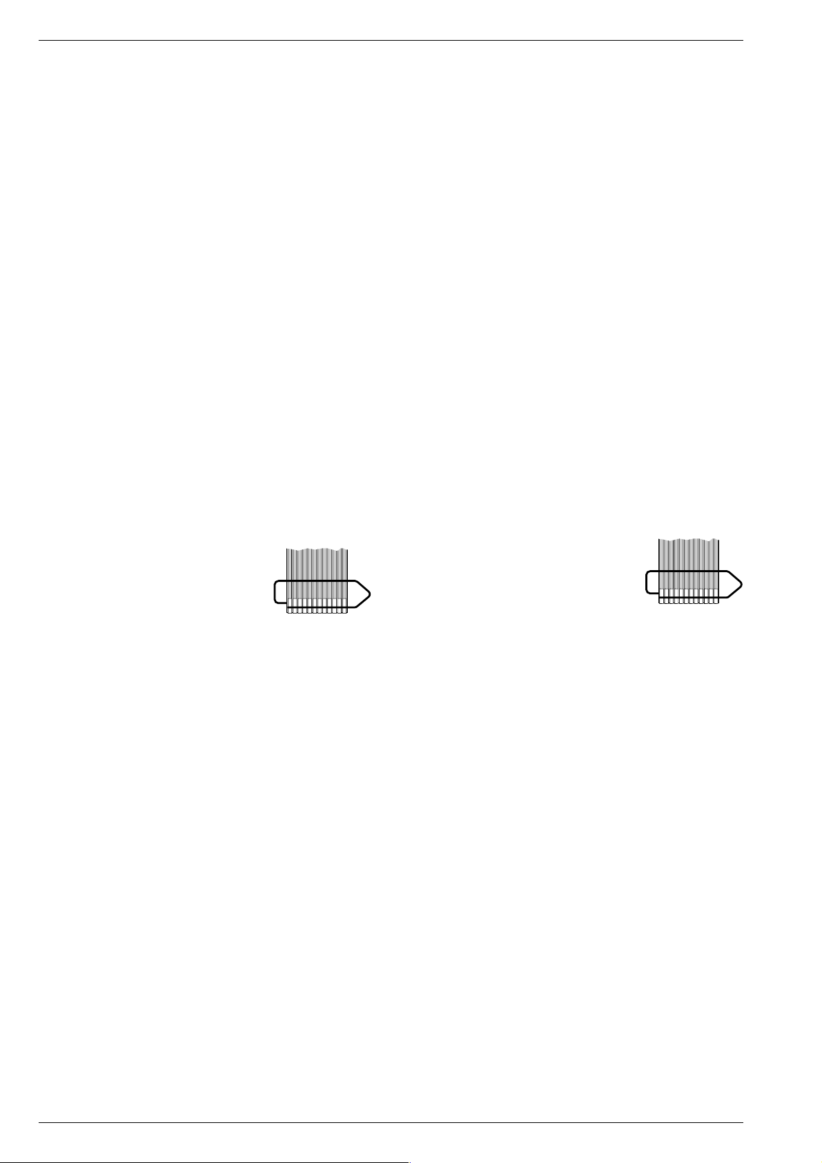
FLEXPRINT
Disassembly Instructions
Opening the Tray when the Drive is defective
– Remove the Drive Mechanism (para 4).
– Push the slider A(Fig. 5) to the left until its stop.
– The tray can be pulled out now.
1. Removing the Power Supply
– Undo 3 screws A(Fig. 1).
– Disengage the 2 locking lugs B(Fig. 1) and remove the Power
Supply.
– Unplug the connectors if necessary.
2. Removing the A/V-MUX Board
– Undo the 5 screws C/Dand the screw E(Fig. 2).
– Remove the panel together with the Adapter Board RS232 or
with the AUX Board.
Attention: When putting the set into operation, observe the mains
connectionsocketTontheAdapterBoardRS232(optional,Fig.1).
– Disengage the 2 locking lugs F(Fig. 3) and remove the A/V-
MUX Board.
– Unplug the connectors if necessary.
3. Removing the Eject Board
– Undo 2 screws G(Fig. 4) and remove the Eject board.
– Unplug the connectors if necessary.
4. Removing the Drive Mechanism
– Undo 4 screws H(Fig. 4).
– Lift the Drive Mechanism (including the shieldings and the DVD-
Monoboard) at its rear side and remove it.
– Unplug the connectors if necessary.
– Remove the shieldings.
4.1 RemovingtheDVD-Monoboard
– Undo 4 screws I(Fig. 5) and remove the DVD-Monoboard.
– Unplug the connectors if necessary.
Attention: Thelaserunit is very sensitive to
static charges (MOS components)!
Therefore, short-circuit the Flexprint to the
laser unit with a paper clip before discon-
necting it.
4.2 Disassembling the Drive Mechanism
– Remove the DVD-Monoboard (para 4.1).
– Undo the screw J(Fig. 4) and remove the microswitch.
– Undo 2 screws B(Fig. 5).
– Unhookthe4rubbershock-mounts C(Fig. 5)andpulloutcarefully
the drive mechanism in direction of the arrow.
Instructions for Mounting a new Drive Mechanism:
– Connect the Flexprint to the laser unit.
– Short the open end of the Flexprint with a paper clip (MOS
protection).
– Remove the factory-applied protective soldering joints from the
laser unit (Fig. 7).
4.3 Disassembling the Drive Mechanism
– Remove the drive mechanism (para 4.2).
4.3.1 Removing the Tray
– Push the slider A(Fig. 5) to the left until its stop.
– Pull the tray out.
– Carefullylift the locking lugEwitha small screw driver(Fig. 6) and
pull the tray out completely.
4.3.2 Removing the Laser Unit
– Disengage the 4 locking lugs F(Fig. 8) and remove the DVD
cover G.
– Unhook the clip I(Fig. 9) and remove the Laser Unit J.
When reassembling, the laser unit must fit in the guides K
(Fig. 10)!
4.3.3 Removing the Loading Motor
– Remove the belt H(Fig. 9).
– Unhook the clip D(Fig. 5) and remove the loading motor.
FLEXPRINT