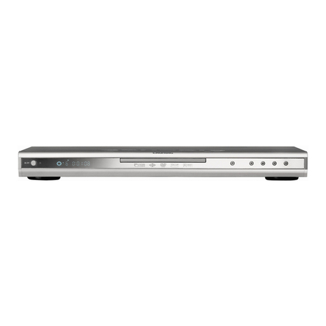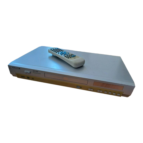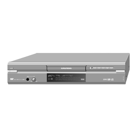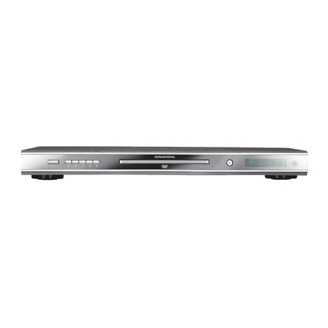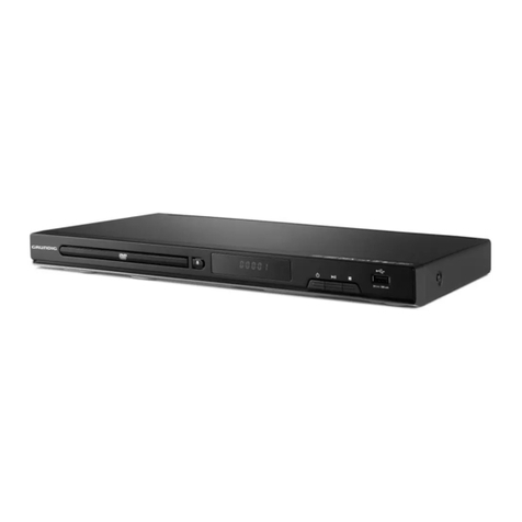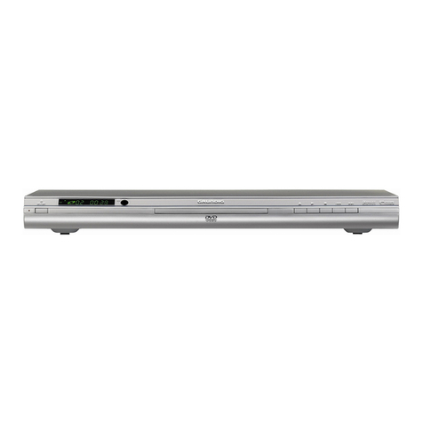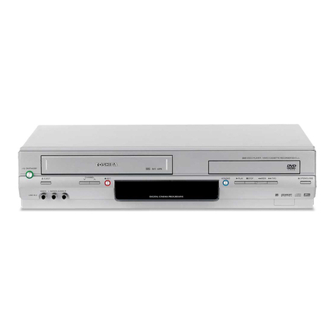
Allgemeiner Teil / General Section GDV 130… / Malaga SE 1210
2GRUNDIG Service
Es gelten die Vorschriften und Sicherheitshinweise
gemäß dem Service Manual "Sicherheit", Material-
nummer 720108000000, sowie zusätzlich die eventu-
ell abweichenden, landesspezifischen Vorschriften!
The regulations and safety instructions shall be valid
as provided by the "Safety" Service Manual, part
number 720108000000, as well as the respective
national deviations.
Table of Contents
Page
Important Hints ................................................................................ 2
IC Block Diagram U 401 ................................................................. 2
Chassis Board ............................................................................... 10
–Main Circuit Diagram ................................................................... 3
–Control Unit ................................................................................. 4
–Audio/Video ................................................................................. 5
–Audio/Video Decoder .................................................................. 6
–Interface ...................................................................................... 8
Keyboard Control Unit ............................................................... 4, 12
Important Hints
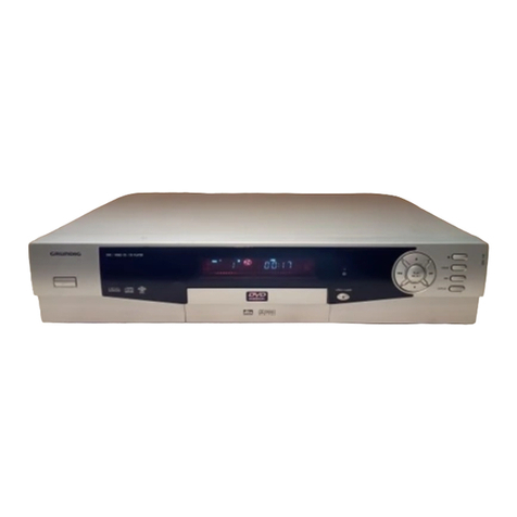
This Service Manual supplement contains the following changed figures
of the printed circuit boards and the corresponding circuit diagrams for:
GDV 130 from serial number 01526010520048456x:
–Keyboard Control Unit (can be identified at the PCB with one clad
side only) Part number 275990200200
–Display U3 Part number 759880565900
–Software (from V6.34) Part number 275990172100
GDV 130 from serial number 01526010520044404x:
GDV 130/2 from serial number 01547240520017294x:
Malaga SE 1210 from serial number 01547560520014350x:
–Chassis Board Part number 275990107900
–IC U401 (ADV7170) Part number 759880565800
–Software (from V2.15) Part number 275990171601
You can order the changed spare parts/software under the given part
numbers at the Spare Parts Service.
General Note
Basic instructions for servicing are given in the following Service
Manuals:
–Service Manual Safety, Part number 720108000000
–Service Manual GDV130, Part number 720105379500
–Supplement Malaga SE1210, Part number 720105379600
Wichtige Hinweise
Diese Service-Manual-Ergänzung enthält folgende geänderte Plati-
nenabbildungen und zugehörige Schaltpläne für:
GDV 130 ab Seriennummer 01526010520048456x:
–Bedieneinheit (erkennbar an der einseitig kaschierten Platine)
Materialnummer 275990200200
–Display U3 Materialnummer 759880565900
–Software (ab V6.34) Materialnummer 275990172100
GDV 130 ab Seriennummer 01526010520044404x:
GDV 130/2 ab Seriennummer 01547240520017294x:
Malaga SE 1210 ab Seriennummer 01547560520014350x:
–Chassisplatte Materialnummer 275990107900
–IC U401 (ADV7170) Materialnummer 759880565800
–Software (ab V2.15) Materialnummer 275990171601
UnterdenangegebenenMaterialnummernkönnenSie die geänderten
Ersatzteile/Software über den Ersatzteil-Service bestellen.
Allgemeiner Hinweis
Grundlage für den Service sind folgende Service Manuals:
–Sicherheit, Materialnummer 720108000000
–Service Manual GDV130, Materialnummer 720105379500
–Ergänzung Malaga SE1210, Materialnummer 720105379600
12 13 14 15 16 17 18 19 20 21 22
3
4
5
6
7
1
2
10
11
8
9
40 39 3841
42
4344 36 35 3437
PIN 1
IDENTIFIER
ADV7170/ADV7171
PQFP/TQFP
TOP VIEW
(Not to Scale)
29
30
31
32
27
28
25
26
23
24
33
V
REF
DAC A
DAC B
V
AA
GND
V
AA
DAC D
BLANK
P13
P14
P15
HSYNC
FIELD/VSYNC
ALSB
V
AA
P5
P6
P7
P8
P9
P10
P11
P12
GND
V
AA
DAC C
COMP
SDATA
SCLOCK
GND
V
AA
GND
RESET
CLOCK
GND
P4
P3
P2
P1
P0
TTX
TTXREQ
R
SET
SCRESET
RTC
IC-Blockdiagramm / IC Block Diagram U401 (ADV 7170)
YUV TO
RBG
MATRIX
VIDEO TIMING
GENERATOR
9
9
810
8
88 10
8
8
810
YCrCb
TO
YUV
MATRIX
SIN/COS
DDS BLOCK
10 10
10
10
10
10
M
U
L
T
I
P
L
E
X
E
R
I
2
C MPU PORT
4:2:2 TO
4:4:4
INTER-
POLATOR
VOLTAGE
REFERENCE
CIRCUIT
SCLOCK SDATA ALSB
HSYNC
FIELD/VSYNC
BLANK
CLOCK GND
DAC D (PIN 27)
DAC A (PIN 32)
V
REF
R
SET
COMP
8
8
8
ADV7170
10-BIT
DAC
COLOR
DATA
P7–P0
P15–P8
10-BIT
DAC
10-BIT
DAC
REAL-TIME
CONTROL
CIRCUIT
SCRESET/RTC
INTER-
POLATOR
ADD
SYNC
PROGRAMMABLE
LUMINANCE
FILTER
10-BIT
DAC
DAC C (PIN 26)
DAC B (PIN 31)
ADD
BURST INTER-
POLATOR
V
AA
Y
U
V
POWER
MANAGEMENT
CONTROL
(SLEEP MODE)
RESET
PROGRAMMABLE
CHROMINANCE
FILTER
CGMS & WSS
INSERTION
BLOCK
TELETEXT
INSERTION
BLOCK
TTXREQ TTX
10
10
10
U
V
Inhaltsverzeichnis
Seite
Wichtige Hinweise ........................................................................... 2
IC-Blockdiagramm U 401 ................................................................ 2
Chassisplatte ................................................................................ 10
–Hauptschaltplan .......................................................................... 3
–Steuereinheit ............................................................................... 4
–Audio/Video ................................................................................. 5
–Audio/Video Decoder .................................................................. 6
–Interface ...................................................................................... 8
Bedieneinheit ............................................................................ 4, 12
