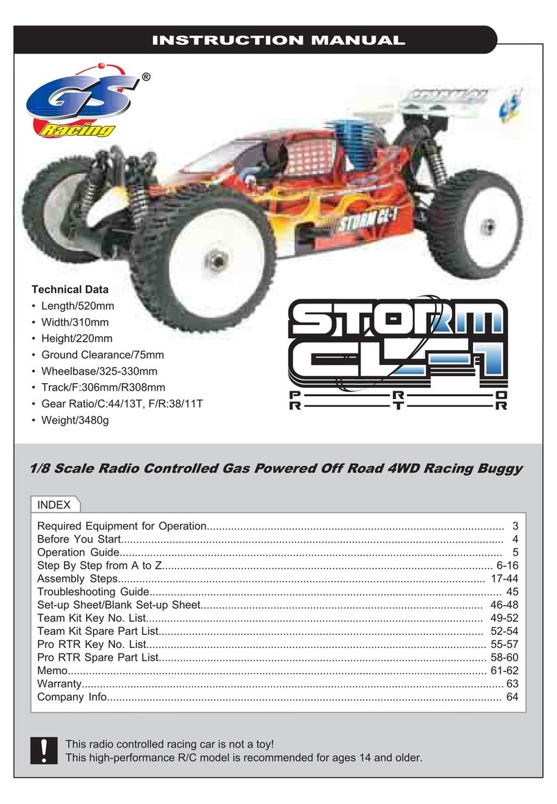
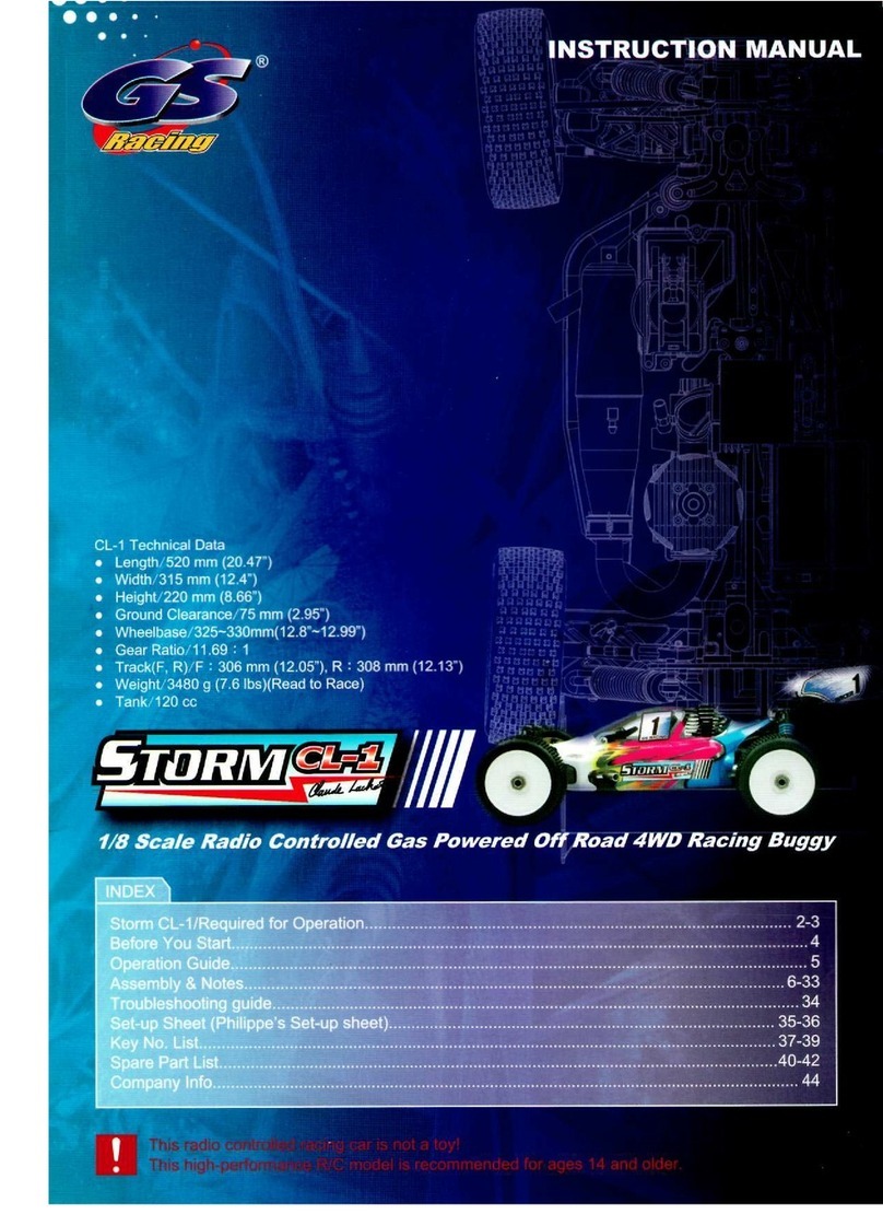
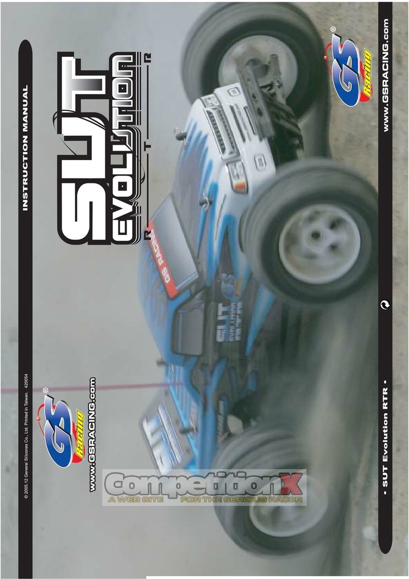
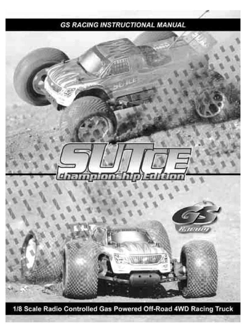
GS Racing Storm Unlimited Truck Championiship Edition User manual

Introduction
Congratulations and thank you for choosing the GS Racing Storm Unlimited Truck Championship Edition,
SUT-CE for short. The SUT-CE is a limited edition, modied, factory spec replica of the truck we have used
to win numerous titles including back to back National Championships. Only 1000 will be produced, so if you
are reading this, you belong to an elite club of RC racers. New for the SUT-CE are the redesigned and longer
chassis, heavy duty suspension mounts, ultra thick steering plate, and Korn Designs pre-painted body. The truck
comes assembled with our team setup installed, so all you have to do is install radio gear, glue tires, and hit the
track. The SUT-CE is a highly developed racing vehicle and is not designed to be an entry level model. Some
mechanical experience and/or parental supervision are required. This manual contains all the basic instructions
to nish assembly of, and break in, operation, and maintenance of your SUT-CE. It is critical that you read all
the instructions in this, and any/all accompanying guides, in order to operate your model correctly and avoid
serious damage. Your hobby dealer cannot, under any circumstances, accept a model for return or exchange
that has been run. We have taken the time to build your truck with our best setup, take the time to follow our
instructions to ensure winning results with your SUT-CE. If you should ever have any questions or need help
with this or any GS product, please feel free to contact our ofcial GS Racing dealers and distributors, as they
will be happy to help you. Good luck and good racing!
Safety Precautions
This is a high performance radio controlled model which needs to be operated with caution and common
sense. Failure to operate your model in a safe and responsible manner could result in personal injury and/or
property damage. It is your responsibility to read and follow all safety precautions. The SUT-CE is not intended
for children under the age of 14 without adult supervision. GS Racing shall not be held liable for any loss or
damages, whether direct, indirect, act of nature, arising from the abuse or misuse of this product or any other
product required while operating this model.
-Fuel can be dangerous is improperly handled. Follow all of the manufacturer’s suggestions.
-Always keep fuel in a cool area and never use near ame, sparks, or while smoking.
- Keep fuel and other ammables out of the reach of children.
-Always run your model in a well ventilated area outdoors. Never run your model indoors.
-All parts of the engine and exhaust can become extremely hot during, and after use. Be careful not to touch
these parts especially when refueling, or making repairs.
- This model creates high levels of noise. Use ear protection is you nd noise objectionable.
-This model is controlled by a radio frequency that is vulnerable to interference from many outside sources.
This interference can cause a loss of control so it is necessary to operate this model in an open area to avoid
personal, or property damage. Always ensure no one is using your frequency before turning on your radio or
model.
- Read, understand, and follow the instruction included with your radio gear.
- Never operate your model near people or property. The speed of this model has the potential for injury and
or damage to people and or property.
Never use anything other than model car fuel.
Never operate the model with a low battery. If the response becomes slow, stop immediately and replace
batteries.
Never run the model without a clean and properly installed air cleaner.
Never run the model lean or allow the engine to overheat.
OPERATION GUIDE
2
Required Equipment
You will need the following items to operate your new SUT-CE: -2 channel surface type radio system, high
speed/torque servos suggested -7.2v 6cell battery Pack (for drill start) -4 “AA” size batteries or 5 cell 6v
receiver pack -20% to 30% percent model car fuel –glow plug igniter –fuel bottle –CA or tire glue –Air Filter
Oil.
Tools Included
Your kit includes the following tools: Allen wrenches, 1.5, 2.0, 2.5, and
3.0 -1 Cross Wrench.
Useful Equipment
You will nd the following items to be useful in the long term operation
of your SUT-CE: - Hobby Grease – Shock and Diff Oils –After Run Oil.
Useful Tools
In addition to the tools supplied with this model you may nd the following useful: small at head and Phillips
screwdrivers –hobby knife –needle nose and or standard pliers –high quality hobby specic (Allen) drivers, 1.5,
2.0, 2.5, and 3.0 –Hobby Scissors –Snap Ring Pliers –Calipers
Other Items Included
The following items are included with your SUT-CE: Pre-painted Korn Designs body, Wing, Antenna Tube and
Cap, Power Start Unit with Shaft, Decal Sheet, Servo Mounts, Servo Horn Inserts, O-Rings, Shock Springs
Spacers, Misc. Hardware.
Getting Started
NOTE: Prior to running your Storm Unlimited Truck-Championship Edition (SUT-CE), read and understand all engine break-
in and operating instructions. If you run you SUT-CE without following the proper break-in procedure, you may damage, or fail to
achieve maximum performance from your engine, and void warranty.
Remove the SUT-CE from the package and remove the body from the model. Check the model over for loose
screws and linkages. Nitro vehicles produce a high amount of vibration, and even through shipping, screws can
come loose.
Your SUT-CE is built to our Team specs, so you don’t have to disassemble the entire truck to make it work
right. Due to air pressure variances during shipping, some oil may leak out of the diffs and shocks. This is
normal and in no way harmful to the performance of the truck. If you notice any leakage, simply wipe clean
with a rag. After each full weekend of racing, we suggest performing routine checks and cleaning on the shocks,
differentials, drive shafts, clutch, hinge pins, bearings, and chassis.
3

Tires
Refer to Step 44 of this manual. Remove the wheels from the model. Glue the tires as described. Reinstall the
wheels to the model.
Radio
Install the radio batteries as recommended by the manufacturer. Next, refer to Step 28 of this manual. Working
backwards to Step 25, remove the radio plate and install the servos, receiver, switch, antenna, and receiver
battery. Reinstall the radio plate and refer to Steps 31 and 34 for proper linkage adjustment. You may need to
remove the air lter to check the throttle linkage.
Ride Height
Your SUT-CE should come preassembled with the proper number of shock spring spacers. These spacers
control the ride height of your truck. During shipping the shocks may ‘settle’. Proper ride height is to have the
suspension arms at or just above level. Add/remove spacers to raise or lower the truck to the proper height.
Wing
Turn to Step 46 of the manual. Attach the wing as described.
Body/Decals
Attach decals as show on the packaging box or to your liking.
Air Filter
The air lter is pre-oiled at the factory. However, it is a good idea to make sure it is well oiled before you re up
the engine. Squeeze the foam of the lter. If it does not leave a residue on your ngers, refer to Step 37 and re-
oil the air lter. Ensure air lter is clean and well oiled prior to each run.
Fueling
Lift the lid of the fuel tank, place the tube of a fuel bottle carefully over the lid of the tank and ll with fuel. Be
careful not to spill fuel on the model.
Glow Plug & Igniter
It is recommended to remove the glow plug from the engine and
attach a fully charged glow igniter to the plug to ensure proper
function. The coil inside the plug should glow orange to red.
(Caution) make sure the glow plug and your hands are clean of any
fuel or ammable residue.
Starting the Engine With Power Starter
To use the GS Power Start you must rst install a properly charged
6 cell 7.2v battery. Insert the shaft of the Power Start into the
drive cup on the back of the engine. Push the red button on the
handle and turn the motor over for 5 seconds to prime the engine.
Now attach a glow igniter to the glow plug and turn the engine
over again. If the engine does not start within 5 seconds, stop, wait
a few seconds and try again until the engine starts.
4

Stopping Engine
There are a few ways to safely shut off the engine. You can pinch the fuel line with needle nose piers, or you
can use the handle of a wrench to stop the engines ywheel. To do this, press the handle against the ywheel to
stop the engine’s rotation.
Engine break in and Adjustments
Your new engine requires an initial
break-in prior to use at full race
settings. During the break-in process
it is recommended to use the same
fuel, nitro, and oil content you plan
to race with. The engine comes with
a break-in or base setting from the factory, but it is necessary to be
familiar with the following adjustments and procedures for the break-in process.
Engine Break in Procedure
The rst two to four tanks of fuel should be
run at a relatively rich setting. Allow the
engine to idle for the entire rst tank of fuel.
During the rst tank of fuel, shut the engine
off for 5 minutes every 5 minutes, and
ensure the piston is at bottom dead center
(rotate the ywheel to the point where the
engine has the least compression.) Both the
high end and low end needles should be set
at a rich mixture. The initial performance of
the engine should be sluggish and upon
acceleration should emit a trail of smoke.
Even at half throttle the engine should still
be putting out a noticeable amount of smoke. Run the model on a at surface and avoid full throttle. Ease on
the throttle slowly and take care to not allow the engine to over rev. While driving the model during the break
in process it may be necessary to raise the idle to achieve proper operation due to the rich needle settings. This
can be put back to the normal setting once the high and low end needles have been adjusted to peak operating
temperature.
Leaner
Richer
Carb Opening
Faster
Slower
Idle Speed
Richer
Leaner
Leaner
Richer
High Speed
Low Speed
5

Understanding Engine Adjustments
The carburetor has a high speed needle
extending up in the brass tube from the top near the air lter. This needle adjusts the air/fuel mixture. The low
speed needle is located lower on the carburetor, facing the throttle servo, inside the rubber boot. The mixture
is referred to as being “rich” when there is to much fuel, and “lean” when there is not enough fuel for the
amount of air entering the engine. A rich setting will result in sluggish acceleration and excessive smoke from
the exhaust. A lean needle setting will cause the engine to hesitate upon acceleration and/or lose power at high
speed. A lean needle setting will cause the engine to run at a higher than normal temperature and will result in
a loss of performance and premature engine wear due to a lack of lubrication to internal engine components.
Using a at head screw driver to turn the needle clockwise in one hour increments will lean the mixture.
Turning the needle in a counter clockwise direction will make the mixture richer. TIP: It is recommended to
always run the motor slightly on the rich side.
Race Tuning the Engine
After the engine has been broken in you can begin to tune it for racing. It is best to tune the engine one needle
at a time, and in one hour increments testing the temperature and performance to avoid premature engine wear.
Run your model a few minutes to warm up the engine. Once the engine is warm, turn the high speed needle
clockwise one hour and check the engine’s top speed. If the top speed is not optimum then again turn the high
speed needle clockwise one hour until the top speed is optimum. When the high speed needle is properly tuned
the engine will accelerate to top speed and maintain that speed with a thin stream of white smoke from the
exhaust. If the high speed needle is leaned past this point it will result in a loss of power and premature engine
wear. It is ideal to tune for optimum performance then richen the needle setting slightly. Once the high end
needle has been set you can then tune the low speed needle. Adjust the low speed needle one hour at a time in
a clockwise direction until the engine will idle for 5 seconds, and accelerates with a very slight sluggishness,
and a noticeable amount of smoke. If the low speed needle is over leaned the engine will hesitate and not
produce a trail of smoke upon acceleration. As you lean the low speed needle you will notice that the idle will
rise slightly and you may have to adjust the idle in a counter clockwise rotation to reduce the engine speed. A
properly adjusted idle screw will allow the engine to idle for 5 seconds yet not allow the model to roll while the
carburetor is in the neutral position. CAUTION: If the engine accelerates to top speed and begins to slow, labor,
or does not leave a thin trail of smoke then the high speed is too lean-stop the engine immediately and allow
the engine to cool. After cooling adjust the high speed needle 2 hours in a counter clockwise direction to richen
the mixture. If you notice the idle speed varying or if the idle cannot be lowered by adjusting the idle screw, the
low speed needle is too lean. Adjust the low speed needle 2 hours in a counter clockwise direction to richen the
mixture.
Testing Engine Temperature
The ideal engine temperature will vary depending on altitude and air temperature but generally should be in
the range of 200 to 240 degrees Fahrenheit. A simple way to check the engines temperature is to place a few
drops of water on the top of the cooling head. It should take a few seconds to for the water to evaporate. If the
water boils away immediately the engine is too hot and should be shut down and allowed to cool. Once the
engine has cooled, you can then richen the high speed needle before restarting. If you wish to use this model for
competition racing there are several hand held digital temperature probes available to the model car market.
High Speed Needle:
As you turn this needle clockwise (leaner) less fuel enters the engine. Turning the needle counter-clockwise
(richer) allows more fuel to enter the engine.
Low Speed Needle:
As you turn this needle clockwise (leaner) less fuel enters the engine. Turning the needle counter-clockwise
(richer) allows more fuel to enter the engine. 6

Idle Speed Screw:
As you turn this needle clockwise it increases the carburetor opening at idle and increases the idle speed.
Turning it counter-clockwise decreases the opening and idle speed.
Warranty and Technical information
The GS-R25MT engine included in the SUT-CE is designed for racing. The GS-R25MT is only warranted
against original factory defects in materials and/or workmanship. Under no circumstances will the engines be
considered under warranty that have been disassembled, operated on anything other than r/c car fuel, run with a
lean needle valve setting or without a proper functioning air cleaner, or used for a purpose for which the engine

T
R
O
U
B
L
E
S
H
O
O
T
I
N
G
•
T
R
O
U
B
L
E
S
H
O
O
T
I
N
G
•
T
R
O
U
B
L
E
S
H
O
O
T
I
N
G
•
TROUBLE SHOOTING GUIDE
Problem
Engine won’t start:
Engine won’t turn over:
Engine starts then stalls:
Engine performing poorly:
Engine overheats:
Engine hesitates:
Engine stalls upon full throttle:
Engine stalls in corners or when idling:
Things To Check
Out of fuel
Spoiled or incorrect fuel
Glow igniter not charged
Engine is overheated
Engine ooded
Air lter clogged
Exhaust blocked
Glow plug damaged
Engine ooded
Engine seized
Clutch seized
Idle set too low
Glow plug damaged
Engine overheated
Low compression/worn engine
High speed needle too rich
Low speed needle too rich
Loose glow plug
Incorrect glow plug for conditions
Dirt in carburetor/engine
Bad fuel
Clutch slipping
Engine overheated
Low compression/worn engine
Binding in drive train
EPA on throttle servo not set properly
High speed needle too lean
Low speed needle too lean
Incorrect glow plug for conditions
Bad fuel
Clutch overload
Air leak in engine or fuel/pressure lines
Engine overheated
High speed needle too lean
Low speed needle too rich
Low fuel level
Bad plug
Bad plug
High speed needle too rich
Low speed needle too lean
Low compression/worn engine
Low fuel level
Low idle setting
Low speed needle too rich
Low speed needle too lean
Clutch seized
Low compression/engine worn
8

Step 1.
Assemble parts in the order shown. Slide bearing (2) onto the Differential Case (1). Build the front and rear diffs
with front/rear out drives (3) and build the center diff with center out drives (4). The front/rear out drives are
round, while the center out drive has a at prole. Apply a light coat of grease (not included) to the male portion
of the out drive and insert it through the Diff Case. Apply a light coat of diff. oil (not included) to the o-ring (5)
and bushing (6) and slide them over the out drive shaft and seat them inside of the Diff Case. Align the hole in
the out drive shaft with the hole in the side of the Diff Case and insert the pin (7) into the out drive. Install the
4x4mm Set Screw (344) into the hole on the side of the Diff Case and tighten until ush. Slide the bevel gear
(8) onto the out drive shaft over the pin, making sure the pin sets in the groove in the bevel gear. Assemble and
install the internal diff. gears as shown using the Bevel Shafts (9), the Small Bevel Gears (10) and Shims (11).
Use care to make sure that the internal diff. gears are seated properly. Note: the grooves in the bevel shafts face
each other. When properly assembled the small bevel gears sit ush with the open end of the diff case.
13
9

Step 2.
The differentials in your SUT-CE come built 10,000cps/front, 50,000cps/center, and 3,000cps/rear GS diff oil.
Center Differential: Slide the Bearing (2) onto the Spur Gear (13). Apply a light coat of grease (not included)
to the male portion of the out drive (4) and insert it through the spur Gear. Apply a light coat of diff oil (not
included) to the o-ring (5) and bushing (6) and slide them over the out drive shaft and seat them inside of the
spur gear. Insert the pin (7) into the out drive and slide the bevel gear (8) over the pin. Apply a light coat of
diff oil to the gasket (14) and place it onto the center diff case. Carefully ll the center diff. with 50,000cps GS
Racing diff Oil to just above where the pins cross. Place the Spur Gear assembly over the center diff housing.
Finish assembly using 4 3x12 RH/ST screws, tightening until snug. Turn the diff and out drives to ensure proper
t and movement. If the diff feels gritty or is bound-up, disassemble and check the internal gears for proper t.
Front and Rear Differentials: Slide the Bearing (2) onto the Large Crown Gear (12). Apply a light coat of
grease (not included) to the male portion of the Outdrive (3) and insert it through the large crown gear. Apply a
light coat of diff. oil (not included) to the o-ring (5) and bushing (6) and slide them over the outdrive shaft and
seat them inside of the large crown gear. Insert the pin (7) into the outdrive and slide the bevel gear (8) over the
pin. Apply a light coat of diff oil to the gasket (14) and place it onto the center Diff. Case making sure the holes
line up properly. Carefully ll one of the diffs with 10,000cps GS Racing Diff Oil (mark it as front) and the
other with 3,000cps GS Racing Diff Oil (mark it as rear). Fill to just above where the pins cross. Place the large
crown gear assembly over the diff housing. Finish assembly using 4 3x12 RH/ST screws, tightening until snug.
Turn the Diff. and out drives and check t again.
Step 3.
Slide 1 Shim (15) onto each diff out drive next to the bearing.* Install 2 bearings (2) into Bulkhead-B (18), 1
inside and 1outside. Slide the small pinion gear (16) into Bulkhead-B. Apply pressure to the pinion gear and
x the front center universal (215) using the 5x5mm Set Screw (345). Apply thread locking compound to the
set screw. Apply a light coat of grease (not included) to the large crown Gear (12) on the diff with 10,000cps
oil, and install the diff into Bulkhead-B. Fit Bulkhead-A using 4 3.5x25mm RH/ST (#346). Make sure the
thin shims seat properly and do not bend. Mark this gearbox as front. Repeat the process using the diff with
3,000cps oil, the longer universal rear driveshaft (181), and mark the gearbox as rear. *Shims: The gear mesh
should be tight without binding. Test t the diff with both shims on the gear-side of the diff and if the diff turns
freely without binding continue to step 4. If the diff binds and does not turn freely (it will make a grinding or
crunching sound when spun), remove a shim from the gear side of the diff and reassemble. If the crown gear
does not make enough contact with the pinion gear (it will make a clicking sound), add a shim to the gear side.
Repeat until you are satised that you have the best gear mesh possible. 10

Step 4.
Mount the Shock Bushings (24) to the outside hole of the Shock Tower (201) with 2 3x23mm Cap Screws (336)
using a mild strength thread-locking compound. Mount the shock tower assembly to the front gear box using 6
3x12mm BH/ST screws (329). Mount the Front Upper Suspension Holder (20) using 2 3.5x16 FH/ST screws
(335). Install the Body Mounts (312) using 2 3x12mm BH/ST screws to the Shock Tower. Mount bumper later.
201
20
201
336
Step 5.
Install the Body Mounts using two 3x12mm BH/ST screws to the Shock Tower. Mount the Shock Bushings
to the outside hole of the Shock Tower with two 3x23mm cap screws. Fasten the pivot balls (29) to the center
hole in the shock tower with two 3x12 cap screws (337) using a mild strength thread-locking compound. Mount
the Shock Tower assembly to the rear gearbox using six 3x12mm BH/ST screws as shown. Fasten rear chassis
brace holder (30) using two 3.5 x 16 FH/ST screws. 11

Step 6.
Assemble Brake Plates (32) and Brake Pads (33) as shown using CA glue. Note direction and location of each
piece. Mount the brake plate-pad assemblies to both Center Diff. Mounts (31) with two 3x12mm Cap Screws
(337). Adjust the oating-brakes by tightening the Cap Screws evenly with both Brake Disks (34) in between
the brake pads until there is the slightest pressure (just until they touch, then back off turn or binding will
occur). This will ensure the perfect amount of play for the brakes. With one Brake Disk in between the brake
pads slide the center diff out drive through the Center Diff Mount (31) and then through the Brake Disk until the
bearing snaps into the Center Diff Mount. Repeat these steps for the other side of the Center Diff Mount. 12

Step 7.
Insert Brake Cam Lever (39) into the Front Brake Cam (36) (the shorter of the two brake cams). Apply a
mild strength thread-locking compound to the 3x4mm Set Screw (338) and tighten the Brake Cam Lever into
position in the Front Brake Cam. Set both Brake Cams into place in the Center Diff. Mount making note of
the front end as indicated in the illustration. Slide the Brake Cam bearings (176) over the brake cams with
the ange side down. Slide the Center Diff. Support Plate (204) over the brake cams and onto the Brake Cam
bearings until seated. Ensure proper t of bearings in the plate and then fasten the Center Diff. Support Plate
to the center diff mounts using four 3x12 BH/ST screws (329). Insert Brake Cam Lever into the Rear Brake
Cam (37). Apply a mild strength thread-locking compound to the 3x4mm Set Screw and tighten the Brake Cam
Lever into position in the Rear Brake Cam. Ensure free movement of the diff and brake cam levers. Loosen the
3x16 cap screws to free up the brake discs is necessary. Note location and direction of brake cam levers (see
insert diagram).
176
176
204
13

Step 8.
Apply a light coat of grease between the touching surfaces of the servo saver arms B and C. Slide the Servo
Saver Spring (45), Servo Saver Arm-C (43), Servo Saver Arm-B (42) onto the Adjustable Servo Saver Pipe
(178). Thread the adjusting nut and tighten until 2mm’s of thread show beneath the nut. Install the Servo Saver
bearings (180) into both sides of the Servo Saver Pipe, and Servo Saver Arm-A (44). Mount the Servo Saver
Shafts (46) to the chassis in the holes shown with the two 4x12mm FH Screws (334) using a mild strength
thread-locking compound. Slide the Servo Savers onto the appropriate Servo Saver Shaft as shown in the
illustration.
Step 9.
Place the hardware in the order shown (make 2). Slide the bearing (ange side rst) and large washer over the
bushing. Place the steering plate as shown over the bellcranks and line up the holes. Slide the bushing assembly
through the plate and bellcranks. Slide the small washer and secure the with the 3mm locknut. Repeat for other
side. Check for smooth operation of the steering plate.
177 177
177
177
178
51
179
342
209
180
50
14

Step 10.
You will make two upper suspension arms. Note the 5x25 turnbuckles have a reverse thread on one side. The
side of the turnbuckle with the extra center groove is a left hand thread, meaning a counter-clockwise rotation
will tighten it into plastic. Thread the M5x25 Turnbuckle (55) into the Front Upper Suspension Arm. Thread the
nylon Ball End (54) on the other end of the Turnbuckle, until there is a 8.2mm gap between them. Increasing
this length will decrease camber. Decreasing this length will increase camber. Camber is the angle of the wheel
relative to the ground when viewed from behind or in front. Snap the 6.8x6mm Ball (56) into the hole in the
Ball End.
Step 11.
Snap the 2.5 E-clip (58) onto one side of the Upper Suspension Hinge Pin (57). Align the upper front suspension
arm so that the Upper Suspension Hinge Pin can be pushed through the upper hole in the front shock tower, into
the upper suspension arm and out through the front upper suspension holder. Push the hinge pin through and
snap an E-clip to the other side of the hinge pin. Repeat for the other side. Ensure free movement of the upper
arm.
15

Step 12.
Fit Bearings (2) into the Knuckle Arm (59, 60) and then slide the Universal Shaft through the bearings. Place
the Knuckle Collars (64) into the holes of the C-hub (61, 62) and carefully slide the assembled knuckle into
the C-hub. Secure the knuckle in the C-hub with two 4x12mm Cap Screws (349) using a mild strength thread-
locking compound. Do not to over tighten knuckle to avoid binding the steering and stripping the threads.
Ensure free spinning motion of the drive shaft. As a precaution, check the universal drive shaft before operation.
The universal drive shaft contains a set screw which holds a pin in place. This set screw may work loose over
time. Remove the set screw using a 2mm allen head wrench, apply thread locking compound to it, and re-install.
62
16

Step 13.
Assemble parts in the order shown making note
of the right and left sides. Fit the right side C-hub
assembly into the Front Lower Suspension Arm (65)
and push the small Lower Suspension Hinge Pin (69)
through the aligned holes. Note direction of both the
suspension arm and the hinge pin. The groove in the
hinge pin must line up with the hole for the set screw.
Secure the Lower Suspension Hinge Pin in the C-hub using the 3x4mm Set Screw (338) (do not over tighten
set screw). Install the 4x12mm Set Screw (348) into the Front Lower Suspension Arm as shown until is extends
out the lower arm 1.5mm. This screw controls the down travel of the lower arm. Repeat the process with the
left C-hub assembly using the remaining front lower arm, and hinge pin. Ensure free movement of the C-hub
assemblies.
Step 14.
Thread one 8.8mm Ball End (70) onto each end of the M5x50 Turnbuckle, Rear Upper Arm (71) until there is a
29mm gap between the ball ends. Note the 5x50 turnbuckles have a reverse thread on one side. The side of the
turnbuckle with the extra center groove is a left hand thread, meaning a counter-clockwise rotation will tighten
it into plastic. Push an 8.8x9mm Ball (72) into one of the 8.8mm Ball Ends until it snaps in. Repeat for
other side. 17

Step 15.
Study the insert illustration to understand how the Rear Toe-In Adjusters (76) work. The holes in the toe-in
adjusters are off center. We suggest that you start with 0.5 degrees of rear outboard toe-in. The rear suspension
mount you will install later provides 3 degrees of rear toe, for a total of 4 degrees. Push the Rear Toe-In
Adjusters, the Bearings (2) and the Rear Universal Drive Shafts (181) into the Rear Hub Carriers (74, 75) as
shown.
Step 16.
Assemble parts in the order shown making note of the right and left sides. Place the Spacers (78) behind the rear
hub assembly. Fit the right rear hub assembly, Spacers, Stopper (77) into the Rear Lower Suspension Arm (73)
and push the small Lower Suspension Hinge Pin (79) through the aligned holes. Secure the Lower Suspension
Hinge Pin (79) in the place by tightening the 3x4mm Set Screw (338) in the Stopper (77) (apply thread locking
compound to the set screw and do not over tighten). Install the 4x12mm Set Screw (348) into the Rear Lower
Suspension Arm (73) as shown until is extends out the lower arm 3.0mm. Repeat the process with the left rear
hub assembly using the remaining rear lower arm, stopper, spacers, and hinge pin. Ensure free movement
of the hub assemblies.
181
18

Step 17b.
Slide the Rear Suspension Mount (213) over the hinge pins and attach to the rear of the rear bulkhead using
2 more 3.5x25mm screws. Secure hinge pins with 3mm set screws. Check for free movement of suspension
assemblies. Install the rear upper arms as shown in Step 17c. Place the assembly on the rear of the chassis (206).
The key in the anti-squat mount will t in the matching key in the chassis. Flip over and attach rear assembly
to the chassis using 4 4x12mm FH screws (334). The nished assembly should look like the photo on the right,
minus sway bars.
346
212 214
REAR SUSPENSION
213
Step 17a.
Attach the Rear Anti-Squat Mount (212) to the front portion of the rear bulkhead as shown using 2 3.5x25 RH/
ST screws. Turn assembly around and insert 4mm hinge pins (214) into mount. Secure with 3mm set screws.
Slide rear lower arm assemblies over the hinge pins, making sure both left and right sides are correctly aligned.
206
Step 17c.
Assemble parts in the order shown one side at a time. Place the universal drive shaft (181) into the diff out
drive. Snap the upper rear control arm onto the pivot ball on the rear shock tower. With the Drive Shaft in
place, slide the upper rear control arm into the top of the rear hub carrier and secure with the 3x25mm Cap
Screw (354) using the inside upper hole. Tighten the 3mm Lock Nut (342) onto the 3x25mm Cap Screw (do not
over tighten as suspension binding may occur). Repeat for the other side.
334
19
181

Step 18b.
Attach the Front Upper Steering Plate (223) to the bulkhead with 2 3x12 BH/ST (329) screws and to the
steering pipes with 2 3x10 BH Screws (370). Insert dog bone portion of the driveshaft into the differential out
drive. Insert the outer end of the upper arms into the front hubs. Attach the upper arms to the hubs using 3x23
cap screws (336) and 3mm lock nuts (342). The nished assembly should look like the photo on the right, minus
sway bars.
Step 18a.
Attach the Front Lower Sus. Rear Mount (211) to the rear portion of the front bulkhead as shown using 2
3.5x25 RH/ST screws. Turn assembly around and insert 4mm hinge pins (214) into mount. Secure with 3mm set
screws. Slide front lower arm assemblies over the hinge pins, making sure both left and right sides are correctly
aligned. Slide the Front Lower Sus. Front Plate (210) over the hinge pins and attach to the front of the front
bulkhead using 2 more 3.5x25mm screws. Secure hinge pins with 3mm set screws. Check for free movement
of suspension assemblies. Place the assembly on the front of the chassis. The key in the front plate will t in
the matching key in the chassis. Flip over and attach front assembly to the chassis using 4 4x12mm FH screws
(334).
Step 18c.
Slide bumper (175) between chassis and bulkhead. Attach bumper to bulkhead with 3x12 BH/ST (329) screw.
Install and fully tighten 4x12mm screws (334) in the forward holes of the chassis to secure bumper and
bulkhead.
346
211
223
329
370
336 342
334
175
334
334
329
20
FRONT SUSPENSION

Step 19.
Assemble 4 sets of linkages by installing 1 short (88) and 1 long (89) ball end to 3x12 set screw (351). Tighten
ball ends until snug. Press 5.4mm ball (94) into short ball end. Note that ange on ball will face the arm. Press
stabilizer ball (92) into other end of linkage. Slide front (90) and rear (91) sway bars into their respective ends
of the truck. The bulkheads contain a groove which the sway bar will seat inside of. Fix the sway bars in place
with 3x8mm BH/ST (369) screws. Do not over tighten these screws. Slide the linkages into the sway bars and
x in place with 3x4mm set screws (338). Attach linkages to arms using 3x15mm BH/ST screws (358).
338
351
338
369
358
369
358
BH/ST
358
BH/ST
369
BH/ST
BH/ST
Table of contents
Other GS Racing Motorized Toy Car manuals

GS Racing
GS Racing Storm User manual

GS Racing
GS Racing Vision RTR User manual

GS Racing
GS Racing SUTCE Operating and maintenance manual

GS Racing
GS Racing Storm User manual

GS Racing
GS Racing Vision RTR User manual

GS Racing
GS Racing Storm Pro User manual

GS Racing
GS Racing STORM CL-1 User manual

GS Racing
GS Racing Storm CL-1 Pro RTR User manual

GS Racing
GS Racing Storm CLX E Pro User manual

GS Racing
GS Racing Sut Evolution RTR User manual