i
Table of Contents
CHAPTER 1: INTRODUCTION ............................................................................................................... 1
E
NCLOSURE
................................................................................................................................................. 1
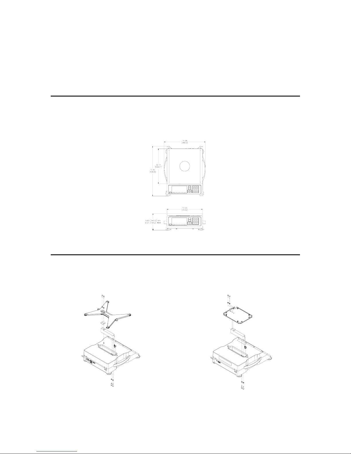
L
OAD
C
ELL
R
EPLACEMENT
......................................................................................................................... 1
Load Cell Connections ........................................................................................................................... 2
K
EYPAD
...................................................................................................................................................... 2
Model 370............................................................................................................................................... 2
MODEL 375........................................................................................................................................... 3
D
ISPLAY
...................................................................................................................................................... 5
Annunciators .......................................................................................................................................... 5
R
EAR
P
ANEL
C
ONNECTIONS
........................................................................................................................ 5
Communication Port 1............................................................................................................................ 6
Remote Display Connections.................................................................................................................. 6
CHAPTER 2: OPTION INSTALLATION................................................................................................ 7
C
OMMUNICATION
........................................................................................................................................ 7
RS-485 Networking................................................................................................................................. 7
20 mA Current Loop Option................................................................................................................... 9
A
NALOG
O
UTPUT
O
PTION
......................................................................................................................... 11
S
ETPOINT
O
PTION
..................................................................................................................................... 12
Setpoint Card Connections................................................................................................................... 13
O
PTION
M
OUNTING
B
RACKET
................................................................................................................... 13
CHAPTER 3: SCALE CONFIGURATION ............................................................................................ 15
E
NTERING THE
S
ETUP
M
ODE
(M
ODEL
370)............................................................................................... 15
E
NTERING THE
S
ETUP
M
ODE
(M
ODEL
375)............................................................................................... 16
S
ELECTING A
P
ARAMETER
......................................................................................................................... 16
C
HANGING A
P
ARAMETER
V
ALUE
............................................................................................................. 17
Selection Parameters............................................................................................................................ 17
S
AVING
P
ARAMETERS
............................................................................................................................... 19
F
ACTORY
D
EFAULT
................................................................................................................................... 20
L
IST OF
P
ARAMETERS
................................................................................................................................20
Parameter Map Details........................................................................................................................ 23
P
RINTING
................................................................................................................................................... 29
Preset Transmit Selections ................................................................................................................... 29
Custom Transmit .................................................................................................................................. 31
A
NALOG
O
UTPUT
P
ARAMETER
S
ETUP
....................................................................................................... 35
Analog Output Example........................................................................................................................ 35
S
ETPOINT
C
ONFIGURATION
....................................................................................................................... 36
Activation Methods (General).............................................................................................................. 37
Percentage Check-Weighing ................................................................................................................ 39
Fill........................................................................................................................................................ 40
Batch..................................................................................................................................................... 41
Discharge ............................................................................................................................................. 43
Both ...................................................................................................................................................... 45
Absolute Check-Weighing..................................................................................................................... 46
Independent Setpoint Operation........................................................................................................... 47
Target Deviation Check-Weighing....................................................................................................... 49
P
ARTS
C
OUNTING
...................................................................................................................................... 50
R
EMOTE
S
ERIAL
O
PERATION
..................................................................................................................... 51
DISPLAY CAPTURE UTILITY............................................................................................................. 51
T
IME AND
D
ATE
S
ETUP
(M
ODEL
370)....................................................................................................... 52