5
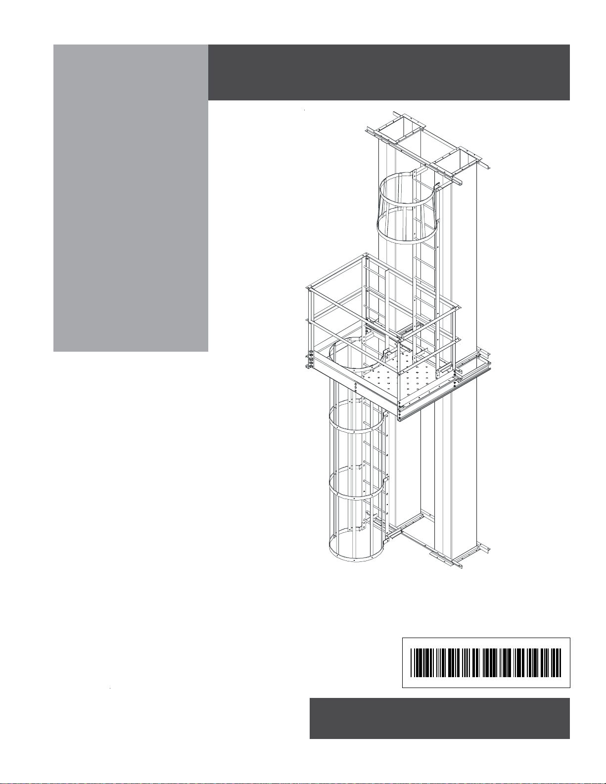
PNEG-1295 16" - 36" Platforms
Introduction........................................................................................................3
Equipment Information ......................................................................................4
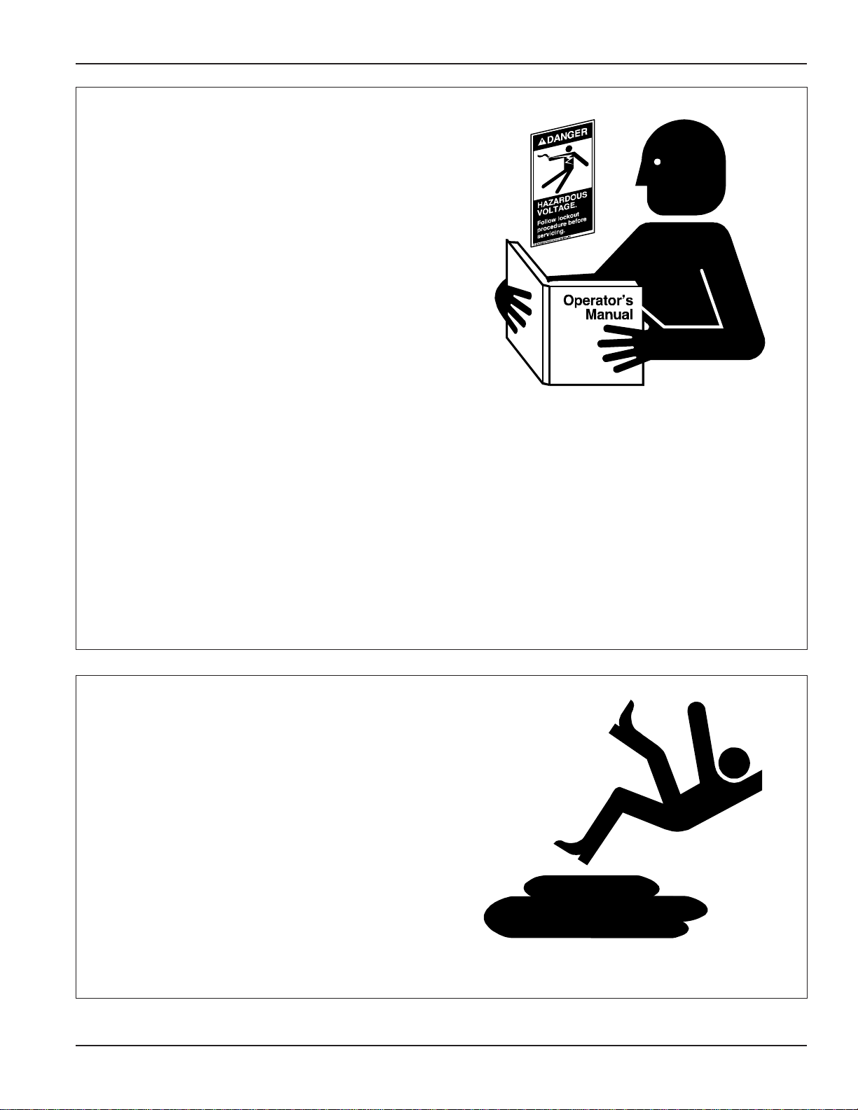
Safety Guidelines .............................................................................................. 6
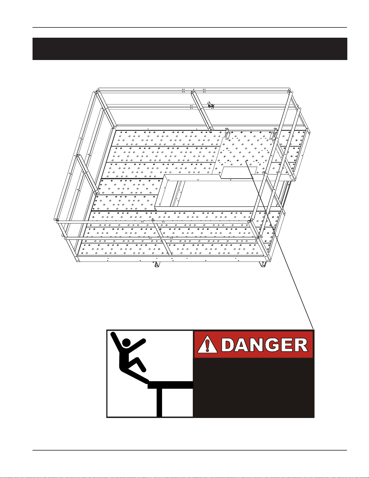
Safety Decal Locations...................................................................................... 9
16" - 24" Platform Assembly
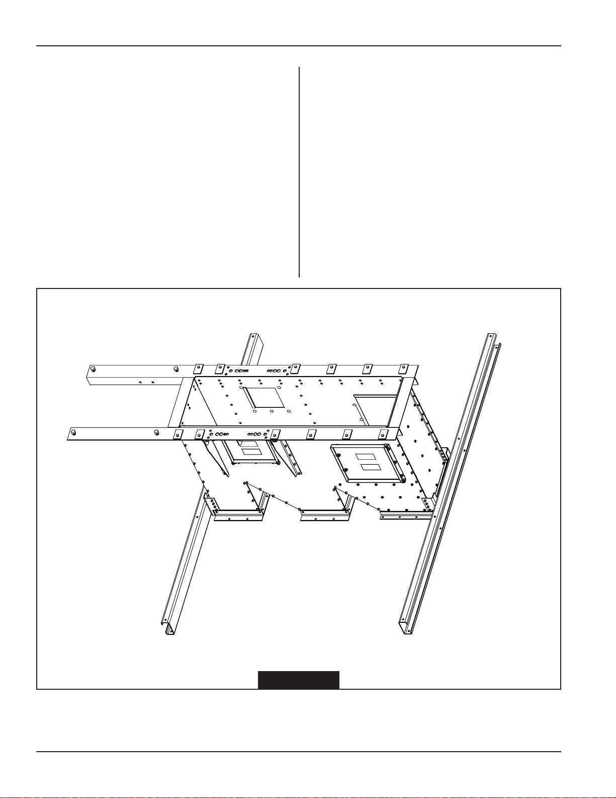
Head Service Platform ................................................................................. 10
Floor Sections .............................................................................................. 11
Toeboards.................................................................................................... 12
Handrail Posts.............................................................................................. 13
Access Door ................................................................................................ 14
Handrails...................................................................................................... 15
30" - 36" Platform Assembly
Platform Support Channel............................................................................ 16
Floor Sections .............................................................................................. 17
Toeboards.................................................................................................... 18
Vertical Posts............................................................................................... 19
Access Door ................................................................................................ 20
Handrails...................................................................................................... 21
Ladder Assembly
Tie Angle Attachments ................................................................................. 22
Tie Angle & Cross Braces ............................................................................ 23
Ladder Stand Off.......................................................................................... 24
Ladder Attachment....................................................................................... 25
Safety Cage Hoop........................................................................................26
14’ Ladder Assembly ...................................................................................27
Safety Cage Vertical Bar.............................................................................. 28
Safety Cage Flare ........................................................................................ 29
Rest Platform
Side Mounting Channels .............................................................................. 31
Platform Corner Posts.................................................................................. 32
Front & Rear Mounting Channels.................................................................33
Center Support Channel .............................................................................. 34
Knee Braces ................................................................................................ 35
Deck Plate ................................................................................................... 36
Top & Mid Handrails .................................................................................... 37
Kickplates .................................................................................................... 38
14' Ladder Assembly at Rest Platform ......................................................... 39
4' x 5' Distributor Platform
Platform Clamps .......................................................................................... 40
Support Channels & Knee Braces................................................................ 41
Platform Deck .............................................................................................. 42
Vertical Posts............................................................................................... 43
Handrails...................................................................................................... 44
6' x 6' Distributor Platform
Platform Clamps .......................................................................................... 45
Support Channels & Knee Braces................................................................ 46
Toeboards.................................................................................................... 47
Platform Decking.......................................................................................... 48
Handrails...................................................................................................... 49
Knee Crossbraces ....................................................................................... 50
Table of Contents
All information, illustrations, photos, and specifications in this manual
are based on the latest information available at the time of publication.
The right is reserved to make changes at any time without notice.