GSi PNEG-1391 Supplement

PNEG-1391
8", 10", & 12" BE-SAW
Unload Auger
Assembly & Operation Manual
PNEG-1391
Date: 5-5-06

Model Number of My BE-SAW:
The manufacturer reserves the right to improve its product whenever possible
and practical to do so. We reserve the right to change, improve and modify
products at any time without obligation to make changes, improvements and
modifications on equipment sold previously.
Date Delivered:
Date Installed:

3PNEG-1391 8",10", & 12" BE-SAW Augers
TABLE OF CONTENTS
Introduction.............................................................................. 4
BE-SAW Numbering System ................................................... 5
Safety ..................................................................................... 6
Decals .................................................................................... 12
Assembly ................................................................................ 14
Assemble Hopper to Incline (8" &10") ............................... 14
Assemble Hopper to Incline (12") ...................................... 16
Assemble Rubber Belting (8", 10", & 12") ......................... 19
Optional Low Profile Hopper (10" & 12") ........................... 20
Incline Tube to Bucket Elevator Boot ................................... 22
BE-SAW Transition ............................................................ 23
Start-Up .................................................................................. 24
Operation ................................................................................ 25
Shutdown ................................................................................ 26
Maintenance ........................................................................... 27
Troubleshooting ....................................................................... 29
Parts ....................................................................................... 30
Hardware Location Charts ...................................................... 50
Table of Content

4
Introduction
PNEG-1391 8",10", & 12" BE-SAW Augers
INTRODUCTION
GENERAL OVERVIEW
The Bucket Elevator Swing Away Auger (BE-SAW) is
pimarily used for unloading grain trucks/wagons. The
BE-SAW hopper is placed under the unload chute
and augers the grain to a new location.
The manufacturer reserves the right to improve its
product whenever possible and practical to do so.
We reserve the right to change, improve and modify
products at any time without obligation to make
changes, improvements and modifications on equip-
ment sold previously.
The BE-SAW Augers have been designed and
manufactured to give years of dependable service.
The care and maintenance of this equipment will
effect the satisfaction and service obtained. By
observing the instructions and suggestions we have
recommended, the owner should receive competent
service for many years. If additional information or
assistance should be required, please contact your
dealer or the manufacturer.
CAPACITY
A. The capacities of augers or screw
conveyers varies greatly under varying
conditions. The following factors play a role in
the performance of the auger:
• Speed
• Angle of operation
• Moisture content
• Amounts of foreign matter
• Methods of feeding
• Different materials
B. An auger operating at a 25° incline might
experience 20% less capacity than an auger
operating horizontally. Twenty-five percent
(25%) moisture could cut capacity by as much
as 40% under some conditions.
GENERAL INFORMATION
READ THIS MANUAL carefully to learn how to properly
use and install equipment. Failure to do so could result
in personal injury or equipment damage.
INSPECT the shipment immediately upon arrival. The
Customer is responsible for ensuring that all quantities
are correct. Report any damage or shortages by
recording a detailed description on the Bill of Lading to
justify the Customer’s claim from the Transport Firm.
THIS MANUAL SHOULD BE CONSIDERED a
permanent part of your equipment and should be easily
accessible when needed.
WARRANTY is provided as part of the company’s
support program for customers who use and maintain
their equipment as described in the manual. The
warranty is explained on the warranty page located on
inside back cover.
This warranty provides you the assurance that the
company will back its products where defects appear
within the warranty period. Should the equipment be
abused, or modified to change its performance beyond
the factory specifications, the warranty will become void
and field improvements may be denied.
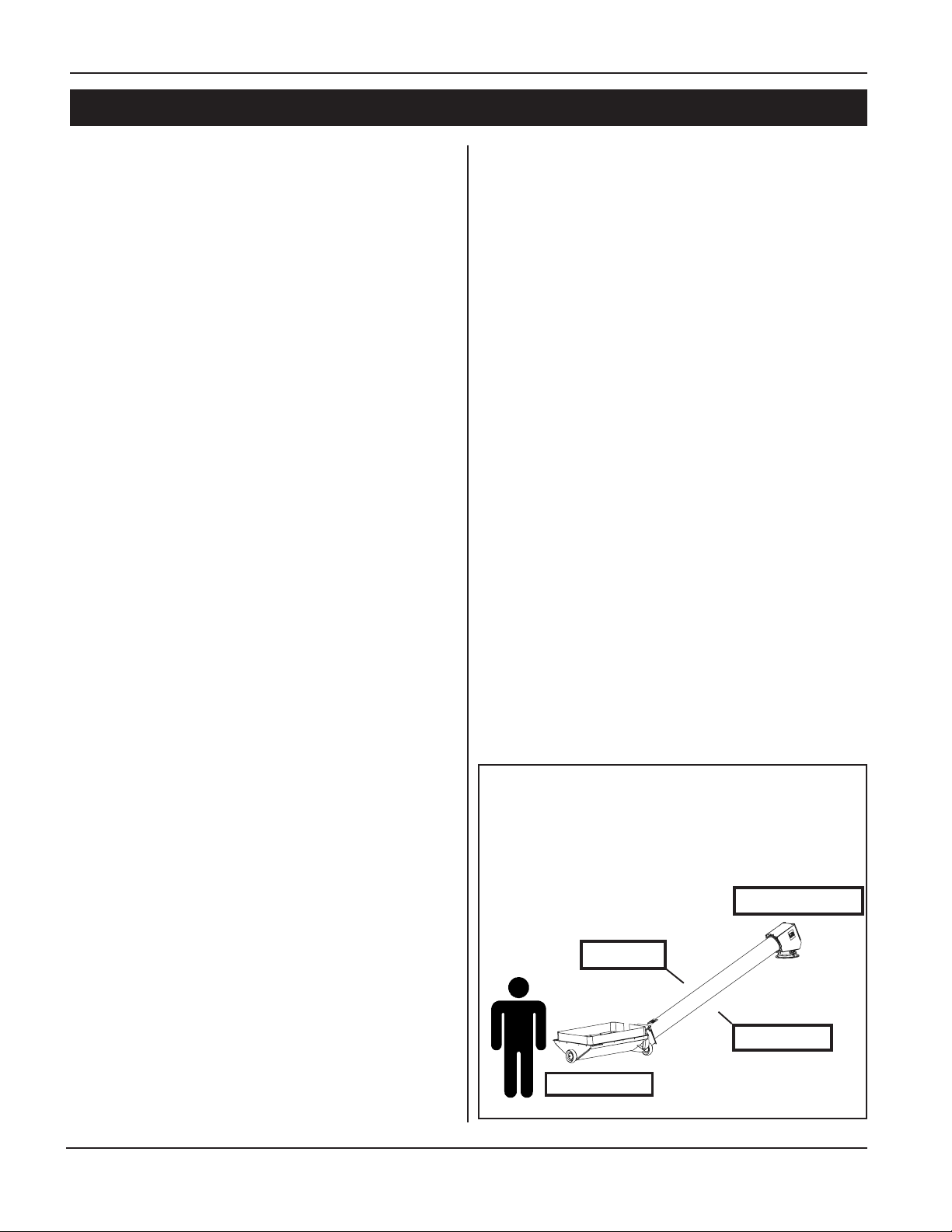
Left Side
Discharge End
Right Side
Intake End
For the purpose of this manual, if you stand at
the intake end of the auger looking towards
the discharge end, your left is the left side of
the auger; your right is the right side of the
auger.

5
Introduction
PNEG-1391 8",10", & 12" BE-SAW Augers
SA XX X XX XX X
Product Diameter Hopper Nominal Capacity Hopper
Line of Profile Length of Flight
Screw of BESAW Thickness
Tube
B = 1/4" Thick14 = 14' 8" 80 = 8000 BPH
L = Low-Profile 70 = 7000 BPH
B = 1/4" Thick
A = Sta ndard
15 = 15' 3"
12 = 12' 8"
80 = 8000 BPH
S = Std Profile 13 = 13' 3" 70 = 7000 BPH A = Standard
12 = 12" Scre
w
13 = 148.125"
L = Low-Profile 10 = 115.125"
B = 1/4" Thick14 = 160" lg 56 = 5600 BPH
A = Sta ndard
13 = 153" lg 50 = 5000 BPH
S = Std Profile 10 = 120" lg 40 = 4000 BPH
10 = 10" Scre
w
B = 1/4" Thick
30 = 3000 BPH
25 = 2500 BPH
A = Sta ndard
12 = 144" lg 20 = 2000 BPH
S = Std Profile 10 = 115.875" 15 = 1500 BPH
08 = 8" Screw
ChoiceChoice Choice Choice Choice
BE-SAW Numbering System

6
Safety
PNEG-1391 8",10", & 12" BE-SAW Augers
This manual contains information that is important for you, the owner/operator, to know and
understand. This information relates to protecting personal safety and preventing
equipment problems. It is the responsibility of the owner/operator to inform anyone
operating or working in the area of this equipment of these safety guidelines. To help you
recognize this information, we use the symbols that are defined below.
Please read the manual and pay attention to these sections. Failure to read this manual
and it’s safety instructions is a misuse of the equipment and may lead to serious injury or death.
SAFETY GUIDELINES
DANGER indicates an imminently hazardous situation which, if
not avoided, will result in death or serious injury.
This is the safety alert symbol. It is used to alert you to
potential personal injury hazards. Obey all safety
messages that follow this symbol to avoid possible
injury or death.
WARNING indicates a potentially hazardous situation which, if not
avoided, could result in death or serious injury.
CAUTION indicates a potentially hazardous situation which, if not
avoided, may result in minor or moderate injury.
CAUTION used without the safety alert symbol indicates a potentially
hazardous situation which, if not avoided, may result in property
damage.
NOTE indicates information about the equipment that you
should pay special attention to.

7
Safety
PNEG-1391 8",10", & 12" BE-SAW Augers
GSI’s principle concern is your safety and the safety of others associated with grain handling equipment.
We want to keep you as a customer. This manual is to help you understand safe operating procedures and
some problems which may be encountered by the operator and other personnel.
As owner and/or operator, it is your responsibility to know what requirements, hazards and precautions exist,
and to inform all personnel associated with the equipment. Avoid any alterations to the equipment. Such
alterations may produce a very dangerous situation, where SERIOUS INJURY or DEATH may occur.
This equipment shall be installed in accordance with the current installation codes and applicable regula-
tions which should be carefully followed in all cases. Authorities having jurisdiction should be consulted
before installations are made.
SAFETY INSTRUCTIONS
OPERATE UNLOAD EQUIPMENT PROPERLY
Make sure ALL equipment is locked in position before operating.
NEVER start equipment until ALL persons are clear of the work area.
Be sure all operators are adequately rested and prepared to
perform all functions of operating this equipment.
NEVER allow any person intoxicated or under the influence of alcohol or drugs
to operate the equipment.
NEVER work alone.
Make sure someone is nearby who is aware of the proper shutdown se-
quence in the event of an accident or emergency.
ALWAYS think before acting. NEVER act impulsively around the equipment.
NEVER allow anyone inside a bin, truck or wagon which is being unloaded by
an auger or conveyor. Flowing grain can trap and suffocate in seconds.
Use ample overhead lighting after sunset to light the work area.
Keep area around intake free of obstacles such as electrical cords, blocks,
etc. that might trip workers.
NEVER drive, stand or walk under the equipment.
Use caution not to hit the auger when positioning the load.
ALWAYS lockout ALL power to the equipment when finished
unloading a bin.
Operate
Unload
Equipment
Safely

8
Safety
PNEG-1391 8",10", & 12" BE-SAW Augers
FOLLOW SAFETY INSTRUCTIONS
Carefully read all safety messages in this manual
and on your machine safety signs. Keep signs in
good condition. Replace missing or damaged
safety signs. Be sure new equipment components
and repair parts include the current safety signs.
Replacement safety signs are available from the
manufacturer.
Learn how to operate the machine and how to use
controls properly. Do not let anyone operate without
instruction.
Keep your machinery in proper working condition.
Unauthorized modifications to the machine may
impair the function and/or safety and affect machine
life.
If you do not understand any part of this manual
and need assistance, contact your dealer.
STAY CLEAR OF ROTATING PARTS
Entanglement in rotating augers will cause serious
injury or death.
Keep all shields and covers in place at all times.
Wear close fitting clothing. Stop and lock out power
source before making adjustments, cleaning, or
maintaining equipment.
OPERATE MOTOR PROPERLY
Do not operate electric motor equipped units until
motors are properly grounded.
Disconnect power on electrical driven units before
resetting motor overloads.
Do not repetitively stop and start the drive in order
to free a plugged condition. Jogging the drive in
this type of condition can damage the equipment
and/or motor components. Electric Shock Hazard.

9
Safety
PNEG-1391 8",10", & 12" BE-SAW Augers
PREPARE FOR EMERGENCIES
Be prepared if fire starts.
Keep a first aid kit and fire extinguisher handy.
Keep emergency numbers for doctors, ambulance
service, hospital, and fire department near your
telephone.
WEAR PROTECTIVE CLOTHING
Wear close fitting clothing and safety equipment
appropriate to the job.
Safety glasses should be worn at all times to
protect eyes from debris.
Wear gloves to protect your hands from sharp
edges on plastic or steel parts.
A respirator may be needed to help prevent
breathing potentially toxic fumes and dust.
Wear hard hat and steel toe boots to help protect
your head and toes from falling debris.
Eye Protection
Gloves
Steel Toe
Boots
Respirator
Hard Hat

10
Safety
PNEG-1391 8",10", & 12" BE-SAW Augers
OPERATOR QUALIFICATIONS
A. The User/Operator must be competent and experienced to operate auger equipment. Anyone who
works with or around augers must have good common sense in order to be qualified. These persons
must also know and meet all other qualifications, such as:
1. Any person who has not read and/or does not understand all operation and safety
procedures is not qualified to operate any auger systems.
2. Certain regulations apply to personnel operating power machinery. Personnel under
the age of 18 years may not operate power machinery, including augers. It is your
responsibility, as owner and/or supervisor, to know what these regulations are in your
area or situation.
3. Unqualified or incompetent persons are to remain out of the work area.
4. O.S.H.A. (Occupational Safety & Health Administration) regulations state:
"At the time of initial assignment and at least annually thereafter, the employer shall
instruct every employee in the safe operation and servicing of all equipment with
which the employee is, or will be involved." (Federal Occupational Safety & Health
Standards for Agriculture. Subpart D, Section 19287.57 (a) (6).
B. As a requirement of OSHA, it is necessary for the employer to train the employee in the safe operating
and safety procedures for this auger. We included this sign-off sheet for your convenience and
personal record keeping. All unqualified persons are to stay out of the work area at all times. It is
strongly recommended that another qualified person who knows the shutdown procedure is in the
area in the event of an emergency. A person who has not read this manual and understands all
operating and safety instructions is not qualified to operate the machine.
Date Employer's Signature Employee's Signature

11
Safety
PNEG-1391 8",10", & 12" BE-SAW Augers
SAFET
Y
1
st
Our equipment is built to provide many years of dependable service to our customers
through durable craftsmanship.
One of the most important aspects of our engineering is SAFETY 1st design
throughout all product lines. Safety is NO ACCIDENT!
That is why we are implementing its SAFETY 1st program. Should you ever need
guards, shields, safety decals, or owner/operator manuals, simply contact us, and
we will supply you with them FREE OF CHARGE!
While it is our main goal to be the world leader in auger manufacturing, it is always
our first priority to keep our customers safe.
If you need any of the above listed safety items or have safety questions, please
contact us:
The GSI Group
PO Box 20
1004 E. Illinois Street
Assumption, IL 62510
Ph: 217-226-4421
Replace missing guards and shields
FREE OF CHARGE!

12
Decals
PNEG-1391 8",10", & 12" BE-SAW Augers
Safety Decals
The Safety Decals listed below are included with the auger. The following page shows the
locations of the decals on the auger. The following pages show a sample of each decal.
Inspect all decals and replace any that are illegible, worn, or missing. Contact your dealer or
the factory to order replacement decals.
3
3
5
1
3
2
4
Ref. # Part # Qty. Description Size
1 DC-1446 1 Caution—General Statements 1-12 (On
Main Auger Housing)
8-1/4" x 4-1/8"
2 DC-1412 1 Danger—Electrocution (On Main Auger
Housing)
8" x 3-3/8"
3 DC-1416 1 Danger—Rotating Auger (On Intake End
of Tube Near Hopper, On Side of Spout
Head, On Underside of Inlet Hopper, On
Side of Inlet Hopper, On Inlet Hopper
Clean-Out Door)
4-1/2" x 5-1/2"
4 DC-1418 1 Safety First—(On Main Auger Housing) 4-7/8" x 3-1/2"
5 DC-1411 1 Danger—Shear Point (On Front of Inlet
Hopper)
4-1/2" x 2-1/16"
Safety Decals

13
Decals
PNEG-1391 8",10", & 12" BE-SAW Augers
3
4
12
Decals are not shown actual size.
Safety Decals
5
1. READ AND UNDERSTAND THE INSTALLATION & OPERATION MANUAL AND ALL SAFETY
INSTRUCTIONS BEFORE OPERATING EQUIPMENT.
2. DO NOT OPERATE WHILE UNDER THE INFLUENCE OF DRUGS OR ALCOHOL.
3. DO NOT OPERATE UNLESS ALL SAFETY EQUIPMENT, SWITCHES, GUARDS AND SHIELDS
ARE SECURELY IN PLACE AND OPERATIONAL.
4. BE SURE EVERYONE IS CLEAR OF THE EQUIPMENT BEFORE ATTEMPTING TO OPERATE
OR MOVING THE MACHINE.
5. ALLOW ONLY TRAINED PERSONNEL IN the OPERATING AREA.
6. KEEP HANDS, FEET, HAIR AND CLOTHING AWAY FROM MOVING PARTS.
7. DISCONNECT AND LOCKOUT POWER BEFORE ADJUSTING OR SERVICING.
8. ELECTRICAL WIRING OR SERVICE WORK MUST BE PERFORMED BY A QUALIFIED
ELECTRICIAN. IT MUST MEET ALL STATE AND LOCAL ELECTRICAL CODES.
9. EMPTY AUGER AND LOWER TO TRANSPORT POSITION BEFORE TRANSPORTING.
10. MAKE CERTAIN ALL ELECTRIC MOTORS ARE GROUNDED.
11. NEVER MOVE MACHINE MANUALLY. ALWAYS USE A TOWING VEHICLE.
12. KEEP CHILDREN AWAY FROM WORK AREA AT ALL TIMES. DC-1446
NOTICE
SHEAR POINT
FAILURE TO HEED
WILL RESULT IN
SERIOUS INJURY OR DEATH!
KEEP FINGERS, HANDS, HAIR AND
LOOSE CLOTHING AWAY FROM
MOVING PARTS.
DC-1411
ELECTROCUTION!!
STAY CLEAR OF POWER LINES!
• THIS EQUIPMENT IS NOT INSULATED FROM ELECTRIC SHOCK.
• KEEP EQUIPMENT AWAY FROM POWER LINES.
• ELECTROCUTION CAN OCCUR WITH OR WITHOUT DIRECT
CONTACT.
FAILURE TO HEED WILL RESULT
IN SERIOUS INJURY OR DEATH!
DC-1412

14
Assembly
PNEG-1391 8",10", & 12" BE-SAW Augers
1. ASSEMBLE HOPPER 8" & 10" AND INCLINE TUBE (See Figure 1-B)
A. Apply grease to the wheel shafts of the
hopper.
B. Attach the hopper wheels to the wheel shafts
using three (3) 5/8" flat washers and one (1)
3/16" x 1-1/2" cotter pin for each wheel. Note:
One (1) to two (2) washers should be used
as spacers between the hopper and the
wheel. Use one (1) washer between the wheel
and the cotter pin.
C. Use the following hardware to bolt the
incline tail stub into the incline flight: (See
Figure 1-A)
• Four (4) rubber sleeves
• Two (2) hex head (Grade 5) cap screws:
For 8" models, use 3/8" x 3" long cap
screws. For 10" models, use 7/16" x
3-1/2" long cap screws.
• Four (4) flat washers
IMPORTANT: When tighten-
ing nylon locknuts, make
sure they are firmly secured
against the rubber sleeves,
but not so tight that they lay
against the flight tube.
Leave a gap of approxi-
mately 1/16".
Nylon
Locknut
Incline
Flight Rubber Sleeve
Flat
Washer
Tail Stub
Flat
Washer
FIGURE 1-A
Flight Connections
D. Attach the u-joint to the incline tail stub using
one (1) hex head cap screw and nylon locknut.
For 8" models, use a 5/16" x 2-1/2" long
(Grade 5) hex head cap screw. For 10"
models, use a 3/8" x 3" long (Grade 5) hex
head cap screw.
E. Attach the u-joint to the bearing stub in the
hopper using one (1) hex head cap screw and
nylon locknut. For 8" models, use a
5/16" x 2-1/2" long (Grade 5) hex head cap
screw. For 10" models, use a 3/8" x 3" long
(Grade 5) hex head cap screw.
Note: Loosen the hanger bearing hardware
for later adjustment.
8" & 10" Standard Profile Hopper Assembly

15
Assembly
PNEG-1391 8",10", & 12" BE-SAW Augers
1. ASSEMBLE 8" & 10" HOPPER AND INCLINE TUBE (CONT.)
Hopper Flight
1/2" x 1-1/4" Long (Grade 5)
Hex Head Cap screw with Flat
Washers and Nylon Locknuts
Note: Install so bolt heads are
on the inside.
Incline Tube
Bearing
Stub
U-Joint
Tail Stub
3/16" x 1-1/2"
Long Cotter Pin
2 Flat
Washers
Hopper Wheel
5/16" x 3/4" Long (Grade 5) Hex
Head Cap screws, Flatwashers,
and Nylon Locknuts
Hinged
Cover
Incline
Flight
Cover Strap
3/8" Locknuts
Hopper Wheel
Hopper
Rubber Sleeve
Hanger
Bearing
The hopper hanger bearing and
bearing stub are preassembled to the
flexible swing-out hopper. In this
assembly drawing, those parts were
exploded away from the hopper to
better show the proper assembly of
the other parts.
F. Attach the lower end of the incline tube to the
front of the flexible swing-out hopper using the
following hardware:
• Two (2) 1/2" x 1-1/4" long (Grade 5) hex
head cap screws
• Four (4) Flat washers
• Nylon locknuts
G. Install the bolt heads onto the inside but DO
NOT tighten completely because the coupler
box must be allowed to pivot.
H. Center hanger bearing on bearing shaft
between hopper flight and u-joint, then tighten.
Swing Out Hopper
FIGURE 1-B
I. Fasten the hinged cover to the front of the
flexible swing-out hopper using two (2) 5/16"
x 3/4" long (Grade 5) hex head cap screws,
flat washers, and nylon locknuts.
J. Install the cover strap over the lid onto the
3/8" stub, which is welded to the box on the
lower end of the incline tube. Use 3/8" nylon
locknuts to hold the straps on the stud.
2 Flat
Washers
Coupler
Box
8" - 5/16"x 2-1/2"
10" - 3/8" x 3"
8" & 10" Standard Profile Hopper Assembly
IMPORTANT: DO NOT
tighten the locknuts down.
The hinged cover must be
able to slide under the
strap when the incline tube
is tilted at different angles.

16
Assembly
PNEG-1391 8",10", & 12" BE-SAW Augers
12" Standard Profile Hopper Assembly
A. Attach the rubber hopper wheel to the back of
the swing-away hopper using two (2) 5/8" flat
washers and 3/16" x 2" cotter pins. (See Fig.
2-B)
B. Fasten two (2) hopper caster wheels to front of
hopper using (4) 3/8" x 1-1/4" long (grade 5) hex
head capscrews and nylon locknuts for each
wheel.
FIG. 2-B
The hopper hanger bearing and bearing stub are pre-assembled on the swing-
away hopper. Therefore, in the drawings, those parts were exploded away from
the hopper to better show the proper assembly of the other components.
Tighten locknuts so the flat washers are firmly against the rubber sleeves.
DO NOT tighten so tight that the flat washers are against the flight tube.
Leave about 1/16" gap.
INCLINE
FLIGHT
RUBBER
SLEEVE
LOCKNUT
FLAT
WASHER
TAIL STUB
FLAT WASHER
INCLINE TUBE
5/8" X 1 1/4" LONG
(GRADE 5) HEX HEAD
CAPSCREW WITH
FLATWASHWER AND
NYLON LOCKNUTS
NOTE: INSTALL SO
BOLT HEADS ARE ON
THE INSIDE
COVER
STRAP
3/8" LOCKNUT
INCLINE
FLIGHT
TAIL STUB
HINGED
COVER
RUBBER SLEEVE
U-JOINT
BEARING STUB
BEARING HANGER
CASTER WHEEL HOPPER FLIGHT
(2) FLAT
WASHERS
3/16" X 2"
LONG
COTTER
PIN
HOPPER
WHEEL
5/16" X 3/4" LONG (GRADE 5)
HEX HEAD CAPSCREWS,
FLATWASHERS AND NYLON
LOCKNUTS
3/8" X 1 1/4" LONG (GRADE 5)
HEX HEAD CAPSCREW AND
NYLON LOCKNUTS
CASTER
WHEEL
C. Remove the incline flight from the incline tube.
D. Attach lower end of the incline tube to the front of
the swing-away hopper. Use two (2) 5/8" x
1-1/4" long (grade 5) hex head capscrews, flat
washers, and locknuts.
E. Connect incline tail stub into the incline flight using
four (4) rubber sleeves, two (2) 1/2" x
3-3/4" long (grade 5) hex head capscrews, flat
washers, and nylon locknuts. (See Fig. 2-A)
FIG. 2-A
2. ASSEMBLE 12” HOPPER AND INCLINE
TUBE ASSEMBLY

17
Assembly
PNEG-1391 8",10", & 12" BE-SAW Augers
F. Using a 3/8" x 3" long (grade 5) hex head capscrew and nylon locknut, attach the u-joint to the incline
tail stub.
G. Slide the lower end of the inclined flighting (the end with the u-joint fastened) down into the upper end of
the incline tubing. Slide the flighting down until the u-joint is near the swing-away hopper bearing stub.
H. Connect the u-joint on the flighting to the bearing stub in the swing-away hopper using a 3/8" x 3" long
(grade 5) hex head capscrew and nylon locknut.
I. Bolt hinged cover to the front of the swing-away hopper using two (2) 5/16" x 3/4" long (grade 5) hex
head capscrews, flat washers, and nylon locknuts.
J. Install cover strap over lid onto the 3/8" stub that is welded to the box on the lower end of the incline
tube. Use the 3/8" nylon locknuts to hold the straps onto the stub.
DO NOT tighten the nuts down. The hinged cover MUST be able to slide un-
der the strap when the incline tube is tilted at different angles.
FIG. 2-C
5/8" LOCKNUT
INCLINE FLIGHT STOP RING
RING
INCLINE TUBE
FLAT WASHER
3/8" X 1 3/4" LONG
(GRADE 5) HEX
HEAD CAPSCREW,
FLAT WASHER AND
LOCKWASHER
19/32" LONG
SPACER
BUSHING
5/8" X 3-1/2" (GRADE 5)
HEX HEAD CAPSCREW
12" Standard Profile Hopper Assembly
2. ASSEMBLE 12” HOPPER AND IN- LINE TUEBE ASSEMBLY (CONT.)

18
Assembly
PNEG-1391 8",10", & 12" BE-SAW Augers
L. Slide head end of the incline flight onto the spout studs. Secure the incline flight in place by using a
5/8" x 3-1/2" long (grade 5) hex head capscrew with a locknut. (See Fig. 2-C on page 17.)
2. ASSEMBLE 12" HOPPER AND IN-LINE TUBE ASSEMBLY (CONT.)
Be sure to install the spacer bushings between the back of the spout and
the ring. After the 3/8" nylon locknuts are tightened, the spout MUST BE
ABLE TO SWIVEL on the incline tube.
FIG. 2-D
3/8" X 1 3/4"
LONG HEX
HEAD
CAPSCREW
WELDED TO
SPOUT
STOP RING
WELDED TO
INCLINE
TUBE
M. Slide incline tube onto the back of the downspout, lining up the holes on the incline ring with the bolts
welded onto the down spout. Fasten using eight (8) 19/32" long spacer bushings, eight (8)
3/8" x 1-3/4" long hexhead capscrews, eight (8) flat washers, and eight (8) 3/8" nylon locknuts.
12" Standard Profile Hopper Assembly

19
Assembly
PNEG-1391 8",10", & 12" BE-SAW Augers
3. ASSEMBLE 8", 10", & 12" HOPPER RUBBER BELTING ASSEMBLY
Swing-Out
Hopper
Rubber
Hopper
Belting
Attachment
Clips
A. Place the rubber belting into the inside of the swing-away hopper.
B. Loosely attach the rubber belting using ten (10) attachment clips and two (2) 1/4” x 1” long hex head
cap screws and nylon locknuts for each clip. The points of the clips should point up and the bolt
heads should be inside the hopper. Use the bolt holes positioned around the upper edge of the
hopper as a guide.
C. Position the belting inside the clips with the belting edge resting on the bolts. As shown on the diagram
on the previous page, the belting should not cover the output end of the hopper. Keep the belting end
within one (1) inch of the clip end.
D. Position the belting evenly around the hopper and through the corners.
E. Tighten the bolts and nuts so that the clip points draw into the belting and the smooth edge of the clips
is in contact with the belting.
1/4" x 1" Hex Head
Capscrew and Nylon
Locknut
Attachment Clip
Rubber
Belting
Hopper
1/4"
Nut
1/4" x 1"
Hex Head
Cap
FIGURE 3-B
Belt Hopper Detail
FIG. 3-A

20
Assembly
PNEG-1391 8",10", & 12" BE-SAW Augers
4. OPTIONAL 10" & 12" LOW PROFILE HOPPER ASSEMBLY INSTRUCTIONS (See Figure 4-A)
Install bolt heads to the
inside and DO NOT tighten
completely. The coupler
box must be able to pivot.
Do NOT tighten the nuts
down. The lid straps must
be allowed to slide when
the incline tube is tilted at
different angles.
There are two installation
heights for the hopper wheels.
For the shortest hopper
profile, use the upper set of
holes. Also use the holes to
angel the wheels by using
opposite holes.
B. Fasten the U- Joint to the incline tail stub us-
ing one 3/8" x 3" long (grade 5) HHCS and
stover nut.
C. Connect the U-Joint to the power shaft in the
swing-out hopper using one (1) 3/8" x 3" long
(grade 5) HHCS and stover nut.
D. Fasten the lower end of the incline tube to the
front of the swing away hopper. Use two 1/2"
x 1-1/2" long (grade 5) HHCS, flat washers,
and nylon locknuts.
E. Bolt hopper lid to the front of the swing out
hopper using three (3) 5/16" x 3/4" long (grade
5) HHCS flat washers, and nylon locknuts.
F. Install lid strap onto 3/8" stubs welded onto
lower end of incline tube. Hold the straps on
the stud with 3/8" nylon locknuts.
G. Low Profile Swing-Out Hopper Rubber
Belting Assembly (See Figure 4-A)
1. Install the rubber belting into the inside of
the swing out hopper. Use ten (10) long
and four (4) short attachment clips to install
the belting. Two (2) 1/4" x 1" long hex head
capscrews and nylon locknuts are used
for each clip. Loosely attach each clip with
grip teeth of clips up and with bolt heads
inside the hopper. Use bolt holes
positioned around upper edge of hopper.
2. Set the belting inside the clips with the
belting edge resting on the bolts. (See
Figure 4-C) The belting does not go
completely across the output end of the
hopper. The belting is notched to
accommodate the center guard support
at the rear of the hopper. Begin installing
the belting at this point and work each way
toward the hopper discharge. Keep the
belting end within one inch of the clip end.
Position the belting evenly around the
hopper and through the corners.
3. Tighten the bolts and nuts to where the
clip points draw into the belting and the
smooth edge of the clips is in contact with
the belting.
A. Install the hopper wheels to the hopper using
four (4) 5/8" x 9-3/4" long clevis pins, four (4)
wheel spacer bushings and four (4) 1-1/4"
cotter pins. Install the hopper wheels so the
front wheels are tilted in towards the incline
tube and the rear wheels are tilted away from
the hopper chain guard. Basically, you want
to tilt your wheels so they follow the arc made
when you move the hopper. (See detail 4-B)
Attachment Clip
Hopper
Hopper
1/4" Nylon
Locknut
1/4" x 1"
Hex Head Cap
FIGURE 4-C
Belt Hopper Detail
Table of contents
Other GSi Tools manuals