GTE KMG-2000-G User manual

GTE Industrieelektronik GmbH
Helmholtz Str. 38 - 40
D-41747 VIERSEN
Tel.: ++49 - (0)2162 3703 - 0
Fax.:++49 - (0)2162 3703 - 25
www.gte.de
KMG-2000-G
compliant - according to the BIA (Professional Institute for Health and Safety at Work) - with
DIN EN 12453 - “Gates - Safe Use of Power-Operated Gates - Test Procedures”
and DIN 16005 – “Automatic Door Systems”
Handheld measuring device for determining the
dynamic and static forces at the closing edges of
doors and gates.

GTE Industrieelektronik GmbH
V3.2UK 2/19 KMG-2000-G Page 2 of 26
1. Technical Data
Power supply:
2 x 1.2V NiMH accumulators
Power consumption:
20 mA
Interface:
USB
Number of graphs stored:
500 single measurements equal to
166 normal measurements each with 3 individu-
al measurements
Temperature range:
-10 .... +60°C
Relative humidity:
20 - 90 % r.h. (non-condensing)
Test surface dimensions:
80 mm ∅, height 50 mm
Dimensions incl. handgrip:
310 x 80 x 50 [mm] (l x b x h)
Weight:
1400 g
Measuring range:
25 N - 2000 N
Measuring accuracy:
typ. < 10 N
25 N -400 N : ±10 N
200 N - 2000 N : ±5% of measurement
Spring constant (mech. filter):
500 N/mm
Rise/fall time:
≤5 ms
Special accessories for KMG-2000 G:
1 special interface cable (for transferring data)
1 software package for the automatic transfer of
the measured values to a laptop or PC
(storage of graphs and protocols for
Microsoft Windows)
Adaptor for mechanically securing the power-
measuring device

GTE Industrieelektronik GmbH
V3.2UK 2/19 KMG-2000-G Page 3 of 26
2. Introduction
The KMG-2000-G force-measuring device is used for the determination of dynamic and
static forces as well as the duration of these at the closing edges of doors and gates.
According to the standard, three single measurements must be made at each test point for
a normal measurement, the mean value of which then represents the measured value that
is relevant for standard purposes. The following four measured values are determined per
measuring operation in order to properly assess the closing force in accordance with the
standard:
1. Static force: Fs
2. Maximum dynamic force: Fd
3. Time in relation to dynamic force range td
4. End force on expiry of the measuring period Fe
of 5 seconds
Permitted Peak Forces in accordance with DIN EN 12453 (Extract)
The static force is the mean value of all the force values within the static time range.
Qualitative Flow of a Closing Force
Fd
Fs
td
ts2
Closing Force
Time
Fd: dynamic force
Fs:
static force
Fe:
end force
td:
duration of dynamic force effect
ts=ts1+ts2: duration of static force effect
td+ts:
total time of force effect
ts
5s
Fe
150N
50N
25N

GTE Industrieelektronik GmbH
V3.2UK 2/19 KMG-2000-G Page 4 of 26
The force graph must be measured three times for each test point. The mean value
is formed from the values obtained for Fd, Fs, Fe and td from each force graph.
These mean values must not exceed the limiting values set.
3. Measuring Device
The measuring device consists essentially of a measuring body complete with the test sur-
face, a centrepiece complete with electronics and a display, and the handgrip complete
with a battery compartment (Picture 1).
Picture 1: KMG-2000-G Force-Measuring Device
Permitted Peak Force
Opening Widths
from 50 to 500 mm
Opening Widths
> 500 mm
Horizontally-moved gate
400 N
1400N
Gate rotating on an axis per-
pendicular to the ground
400N
1400N
Vertically-moved gate
400N
400N
Gate rotating on an axis parallel
to the ground
400N
400N
Barriers
400N
400N

GTE Industrieelektronik GmbH
V3.2UK 2/19 KMG-2000-G Page 5 of 26
3.1. The KMG-2000 G force-measuring device is used for the routine, on-the-spot check-
ing of the closing forces on gates, e.g. following the installation of a new gate or for
the prescribed annual inspection of existing gates, with the result being recorded in
the inspection log book relating to each gate. It is possible to transfer the measured
values to a laptop or PC via the inbuilt USB interface which allows an accurate analy-
sis of the measured values to be carried out and any deviations from the set values
to be identified. The required software can be ordered as an extra.
3.2. It is stipulated in EN 12453 and DIN 16005 that each force-measuring device must be
sent to the manufacturer at least once a year for the purpose of calibration and ad-
justment. He will then test that it is compliant and approve the device for use for an-
other year.
3.3. The centrepiece of the KMG-2000-G contains an LCD display, on which all the
measured values, the force curves, the measured-value memory management func-
tion and user guidance are displayed.
•Measured-Value Display
All 4 measured values that are relevant for standard purposes are displayed simul-
taneously for each individual measurement and, following the third individual
measurement, the 4 mean values.
Individual Measured Values Mean Values
•Measured-Value Memory Management Function
All measured values of the individual measurements, up to 500 in number, and the
mean values calculated in each case from 3 individual values can be brought up on
the display along with their graphic representations.
•User Guidance
During the individual phases of the measurement process appropriate operating
advice is displayed, e.g.
Measurement
is calculated
Please wait
Fd : 325N 28/2
Fs: 51N < F1
Fe: 0N > F2
Td: 40ms F3
Fdm : 275N 28/2
Fsm: 46N < F1
Fem: 0N > F2
Tdm: 40ms F3

GTE Industrieelektronik GmbH
V3.2UK 2/19 KMG-2000-G Page 6 of 26
4. Measurement of a Force Sequence
4.1 Carrying Out The Force Measurement
•Switch on (actuate any button as desired)
After switching on, the “start” display appears for
5 seconds:
During this time the language selection or the
options menu can be selected.
After 5 seconds the device is ready to carry out
force measurements.
The current status of the measured-value
memory is displayed top left, e.g.:
2. Normal measurement
3. Individual measurement
If the current normal measurement No.2 is to be cancelled, then by pressing button F2 it
is possible to switch ahead to normal measurement No.4. There will then be 3 indivi-dual
measurements available once more.
•Initialise measuring
A measuring operation is activated by pressing
button F3. The device is now ready to take meas-
urements. The measuring operation is started if a
force > 20 N is exerted on the test surface. The
force/time measuring operation then runs (for a
measuring period of 5 seconds).
•Carry out measuring operation
Hold the test area centrically (inner circle) to the
measuring points stipulated in the European draft
standards. The measuring points are specifically
prescribed in relation to the relevant type of gate
construction. (see Appendix).
Once the trigger threshold of 20 N has been
passed, the force is measured over a period of 5
seconds. During this time the message “Measure-
ment - Please wait” is displayed.
StM: 2 SiM:3
Options F1
New StM F2
Activate F3
KMG-2000-G GTE
Options F1
Language F2
Exit F3
StM: 2 SiM:3
Options F1
New StM F2
Start: F > 20N
Measurement
Please wait

GTE Industrieelektronik GmbH
V3.2UK 2/19 KMG-2000-G Page 7 of 26
Once measuring has been completed, the
force/time graph is analysed automatically and
the values that are relevant to the standard are
determined.
•Display measured values
Following evaluation, the course of the force over
the measurement period (5secs) is initially dis-
played and the dynamic force Fd (peak force) dis-
played as a value.
Normal 5sec. range display
Button F1: To switch between ‘normal display’
(5sec measuring range) and ‘zoom display’
of the dynamic range (1sec measuring range)
Zoom display over 1sec dynamic range
Button F2: To switch to display of 4 measured values:
Max. dynamic force: Fd in N
Static force: Fs in N
End force after 5 seconds: Fe in N
Duration of dyn. force range: td in ms
Button F3: Cancellation of display mode
Once the third measurement has been taken, the
totals of 3 individual measurements required for
the normal measurement have been made. If but-
ton F3 is now actuated, the mean values of the 3
individual measurements are displayed. The mean
values are identified by the addition of an “m”. But-
tons F1 and F2 do not have any function as the
graphic representation of the mean values makes
no sense.
If the mean values are displayed, the display
mode can be cancelled using F3.
Measurement
is calculated
Please wait
Fd : 369N 3/1
Fs: 82N < F1
Fe: 17N > F2
Td: 128ms F3
Fdm : 237N 3/3
Fsm: 58N < F1
Fem: 12N > F2
Tdm: 86ms F3
362N
362N

GTE Industrieelektronik GmbH
V3.2UK 2/19 KMG-2000-G Page 8 of 26
•Additional Measurements
You can return to the main menu by actuating
button “F3”
and to the “Start F>20N” display by actuating
button “F3” once again
4.3 Storage of the Measurement Data and Graph via a Personal Computer
The KMG-2000 G can be connected to any normal PC via a data link (USB). To do this,
the cable supplied is connected to the USB jack on the KMG-2000 G and to a USB inter-
face on the PC. Before data can be read off the KMG-2000-G the device must be switched
on and the ‘KMG-VD 2005’program on the computer which has been connected up must
be started. The software tests the connection and alerts you to any mistakes in connection
or malfunctions.
The KMG-2000 G can store a total of 500 graphs (equivalent to 166 normal measurements
with 3 individual measurements). The data is preserved, even after the device has been
switched off, with the result that the force graphs can also be read off the KMG-2000-G
during a subsequent period.
The individual functions can be called up via the program menu of the software. You can
find further explanations in the online help.
Figure 2: KMG-2000-G force-measuring device with analysis and protocol software
NM: 2 IM:3
Options F1
New StM F2
Start: F > 20N
StM: 2 SiM:3
Options F1
New StM F2
Activate F3

GTE Industrieelektronik GmbH
V3.2UK 2/19 KMG-2000-G Page 9 of 26
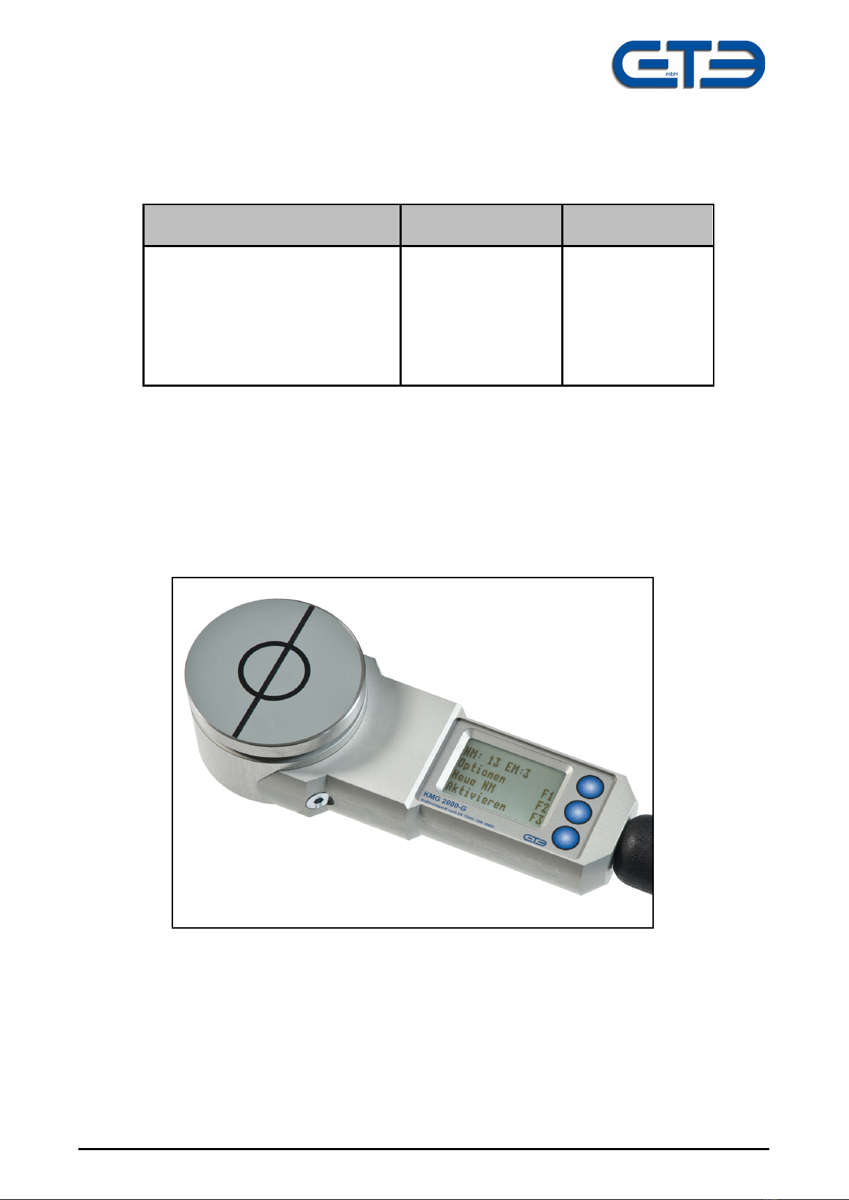
Active Mode
Man (Auto) F1
Exit F3
5. Menu Options
5.1 General Advice
The function keys F1, F2 and F3 are used for calling up menu functions and for operating
the device. The function of the keys is given by the symbols F1, F2 and F3 on the display.
If keys are not represented by these F symbols on the display, then those keys that are not
represented have no function or all keys have the same function. For approx. 5 seconds
after switching on the KMG a menu is displayed allowing “Options” and “Language“ to be
selected.
F1: Options Call up menu for settings
F2: New NM Initiate new normal measurement
F3: Activate Activate measuring
The menu points “New NM” and “Activate” have already been explained in Section 4.
5.2 “Options” Menu
The various options can be selected one after the
other via button F1. F2 activates the option dis-
played.
The number of the current option of a total of 6 is
displayed top right.
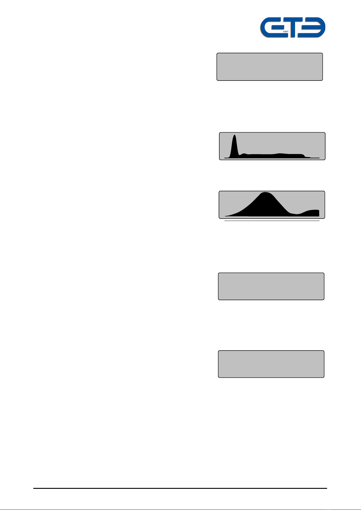
5.2.1 Option 1: Activation Mode
In the activation mode the type of “ready to meas-
ure” mode can be set. Button F1 switches the activa-
tion mode between “Automatic” and “Manual” and
switches back to the main menu. The illustration
shows that the “Manual” activation mode has been selected. Button F3 cancels the activa-
tion menu.
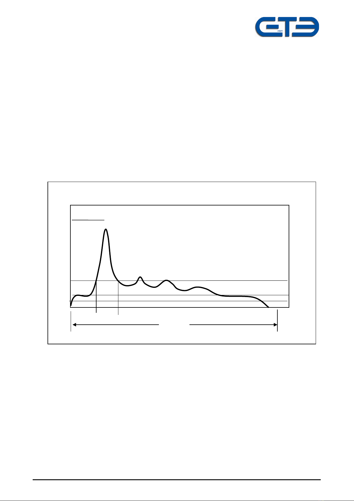
“Auto” Activation Mode: After every measurement the device is automatically switched
to “ready to measure”. As soon as a force > 20N acts on the test surface, a new force/time
graph is plotted and then the current graphic is displayed and the measured values stored.
This mode is used to record several measurements one after the other which should be
triggered automatically by kicking the test plate.
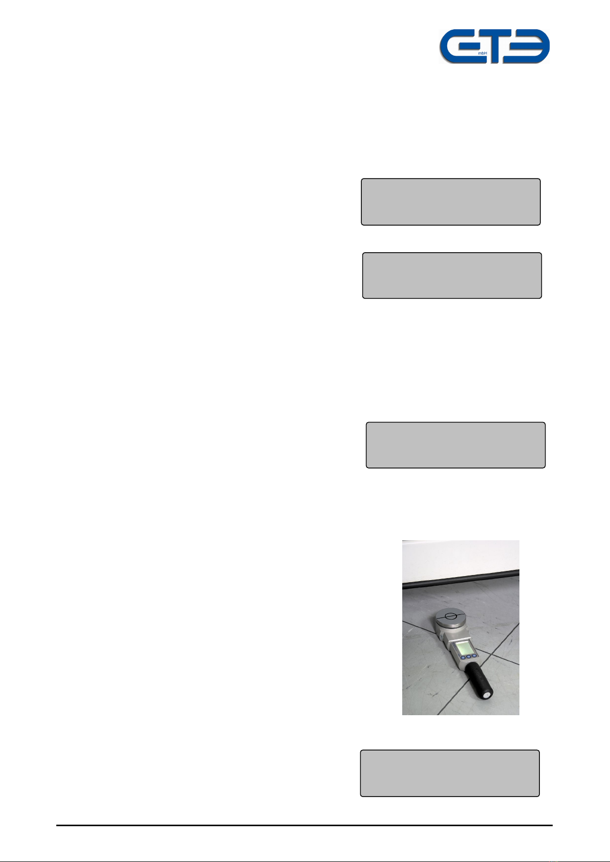
'Manual' Activation Mode:Prior to each new measurement the display must be switched
from showing the graph to showing the measured values using any button as desired. A
new measurement is then activated using button “F3”. At this setting the measurement of
the force cannot be triggered inadvertently by kicking the test plate.
Options (1/6)
Next function F1
Activ.-mode F2
Exit F3

GTE Industrieelektronik GmbH
V3.2UK 2/19 KMG-2000-G Page 10 of 26
Options (2/6)
Next function F1
Delete results F2
Exit F3
Delete results
all results F1
Last StM F2
Last SiM F3
Options (3/6)
Next function F1
Show results F2
Exit F3
5.2.2 Delete Mode = F2
In order to prevent accidental deletion, button F2 must
be pressed for longer than 3 seconds.
The following delete functions can be selected on the
delete menu:
F1: entire memory is deleted
F2: last individual measurement is deleted
F3: last normal measurement along with its 3 individual measurements is deleted.
After actuating one of the selection buttons relating to the type of measurement values,
you are asked once more in a further menu whether the measured values selected should
be deleted.
F1 = Yes
F3 = No
Please Note: By actuating F1 the data selected will be deleted.
5.2.3 Check on Measured Values Held in Memory
By actuating button F2 the control display relat-
ing to those measured values deposited in the
memory is called up.
The item stored ,normal measurement / single
measurement no., is displayed top right, e.g. in
this case: 2 individual measurements within the
28th normal measurement
F1 previous measurement
F2 next measurement
F3 display of the relevant force/time graph
After flicking through 3 individual measurements in
each case the relevant mean values appear.
These are identified by an “m” on the display.
Undershooting or overshooting the measured value memory is prevented by the internal
logic.
Fd : 325N 28/2
Fs: 51N < F1
Fe: 0N > F2
Td: 40ms F3
Fdm : 325N 28/3
Fsm: 51N < F1
Fem: 0N > F2
Tdm: 40ms F3

GTE Industrieelektronik GmbH
V3.2UK 2/19 KMG-2000-G Page 11 of 26
Options (4/6)
Next function F1
Illumination F2
Exit F3
Options (5/6)
Next Function F1
Beeper F2
Exit F3
Options (6/6)
Next Function F1
Turn-Off time F2
Exit F3
Turn-Off Time:
6 Minutes < F1
> F2
Storage F3
5.2.4 Lighting Adjustment
On this menu the lighting of the display can be
switched on or off using button F1.
5.2.5 Annunciator
On this menu the internal annunciator can be switched
on or off using button F1.
The annunciator gives an audible signal once measuring has been completed.
5.2.6 Switch-Off Time
The device does not have an on/off switch.
After the device has been switched on by pressing
any button as desired, it switches off automatically after
a period of time that can be selected once no more
buttons have been actuated or there is no
communication.
Using button “F2” the time is increased
Using button “F1” the time is decreased
Different times can be set ranging from 2 - 30 minutes
Please Note: The KMG-2000 G has no on/off switch.
The device is switched on by pressing any button as desired and auto-
matically switches off after a set time.

GTE Industrieelektronik GmbH
V3.2UK 2/19 KMG-2000-G Page 12 of 26
5.3 Language Selection
Language selection is only available after the
device is switched on. As the device does not
have an off-switch, you must wait until it switches
off automatically and then switch the device back
on.
You have access to the menu for selecting
national languages from the loaded menu after
switching the device on by pressing button F2.
Actuating the relevant button selects the desired
national language and switches the device over to
“ready to measure” mode.
KMG 2007 GTE
Options F1
Language F2
Cancel F3
German F1
English F2
> F3
French F1
Italian F2
> F3
Spanish F1
End > F3

GTE Industrieelektronik GmbH
V3.2UK 2/19 KMG-2000-G Page 13 of 26
Charge
batteries
Exit F3
Batteries
low
Exit F3
6. Warning and Error Messages
6.1 Battery Monitoring
Whilst in operation the state of the rechargeable
battery is checked. If the battery is really low, the
following message appears:
With the present level of charge further measure-
ments can still be made.
If the “batteries low” message appears, the
accumulators are depleted and must be charged up.
Changing batteries is not necessary as the device con-
tains 2 rechargeable batteries. Changing batteries is only required in the event of the bat-
teries having sustained damage.
As the batteries are monitored by an integrated charging regulator whilst charging and dis-
charging, exchanging the batteries is only to be expected at the end of their useful life
(which is several years).
Charging of the batteries is essentially carried out via the USB jack of the KMG.
3 charging modes are provided for in this connection:
a) The power pack included is fitted with a USB jack.
b) The measuring device is connected via the USB cable to an adaptor used for car ciga-
rette lighters
c) The KMG is charged whilst the USB is connected to a computer via the USB interface.
Charging Adaptor for Mains Operation (230V) and Car Power Supply (12V)
The shortest charging time is achieved using the plug-in power unit. If the batteries are flat,
the charging time is approx. 3 - 4 hours.

GTE Industrieelektronik GmbH
V3.2UK 2/19 KMG-2000-G Page 14 of 26
Operating display:
a) with no KMG connection: LED at green
b) charging process: LED at red
c) charging process completed, holding charge: LED at green for 19 secs and at red for 1
sec.
The average power consumption in the case of an unlit display is approximately 20 mA,
and in the case of a lit display approximately 40 mA. This gives an operating life of approx-
imately
80 hours in normal display mode and approx . 40 hours in the case of a lit display.
6.2 Storage Space
Whenever the KMG switches to the “ready to measure”
mode and the capacity of the memory is exhausted, the
following message is displayed:
After actuating F3 branching off to the options menu
occurs
Tip
The device has a measured-value memory capable of storing a total of 500 graphs.
This means:
a) 166 normal measurements @ 3 individual measurements
b) All 500 ‘normal measurements’ @ 1 single measurement
c) Other combinations of normal/individual measurements
6.3 Memory Space Empty
If, on the menu in 5.2.3, Check on Measured Values
Held in Memory, the memory flicks through and
no data is found in the memory bank, the following
message appears:
6.4 Device Still Loaded
In case the KMG is still loaded with a force higher
than 50N if the measurement is started manually the
display will indicate the following message:
By pressing the key F3 the measurement can still be started ignoring the current load.
However in this case the measurement accuracy will not be granted!
If this warning is indicated without a load on the measurement area, the force gauge
should be sent for maintenance to the GTE service department.
Memory empty
Exit F3
Numbers
exhausted
Options F1
Device still loaded
Exit F3

GTE Industrieelektronik GmbH
V3.2UK 2/19 KMG-2000-G Page 15 of 26
Extract from DIN EN 12453
Safety in use of power operated doors – Test methods –
3.2 Measuring Points
A measuring point is the place where the measurement of entrapment forces
at doors must be made. Three (3) measurements must be taken at each
measuring point. The mean average value obtained at each point has to
meet the specified requirements. In the following, measuring points are de-
fined for different door types, taking into consideration:
- Opening width:
Opening width is the clear distance between the primary closing edge and
the counter closing edge i.e. between the leaf and surrounding solid parts.
- Direction of measuring force
Direction of measuring force is parallel to the line of application of the spring
force of the measuring instrument effected by the leaf during the process of
measuring. The line of application synchronises with the centre line of the
spring inside the measuring instrument, it also passes the centre points of the
head of the measuring instrument.
3.2.1 Sliding door
On a sliding door, the entrapment forces will be measured on both primary
closing edges and rear edge, as follows:
3.2.1.1 Measuring between the primary closing edge and the counter closing edge
should be done in reference to figures 1 and 2 below:

GTE Industrieelektronik GmbH
V3.2UK 2/19 KMG-2000-G Page 16 of 26
Figure 1: Measuring points at the leaf of a sliding door.
Figure 2: Opening widths between the primary closing edge
of a sliding door and the counter edge

GTE Industrieelektronik GmbH
V3.2UK 2/19 KMG-2000-G Page 17 of 26
3.2.1.1.1 Measuring Points
Measurement of forces shall be carried out at the height of
- 50 mm above the lower edge of the door,
- the middle of the primary closing edge, or, at a height of 2500 mm
above the floor in case that length of the primary closing edge is
greater than 5000 mm,
and
-300 mm below the upper edge of the door leaf, or, at a height of 2500
mm above the floor where the length of the primary closing edge is
greater than 2800 mm,
and at the opening width of
- 50 mm
- 300 mm
and
500 mm between the primary and the counter closing edge.
3.2.1.1.2 Direction of measuring force
The forces must be measured parallel to the direction of movement of the
primary closing edge.
3.2.1.2 Measuring between the rear edge of the leaf and sourrounding solid parts.
Measurements should be taken between the rear edge of the leaf and sour-
rounding solid parts in the same way as for the entrapment forces between
the primary and counter closing edges (3.2.1.1.).
The opening width should be chosen between the most prominent parts on
the rear edge of the door and those on its surroundings.

GTE Industrieelektronik GmbH
V3.2UK 2/19 KMG-2000-G Page 18 of 26
3.2.2 Hinged doors
On hinged doors, the entrapment forces must be measured on both the pri-
mary closing edge and the door leaf itself as shown below, in figures
3 and 4:
Figure 3: Measuring points at the leaf of a hinged door

GTE Industrieelektronik GmbH
V3.2UK 2/19 KMG-2000-G Page 19 of 26
Figure 4: Opening widths between the leaf of a hinged door and the counter closing edge
3.2.2.1 Measuring between the primary and the counter closing edges
3.2.2.1.1 Measuring points:
Measurement should be carried out at the height of
- 50 mm above the floor,
-mid-way up the door leaf, or, at a height of 2500 mm above the floor,
where the height of the door leaf is greater than 5000 mm,
and
-300 mm below the upper edge of the door leaf, or, at a height of 2500
mm above the floor, where the height of the door leaf is greater than
2800 mm,
and at the opening width of
- 50 mm
- 300 mm
and
-500 mm between the door leaf and the counter closing edge facing the
leaf.

GTE Industrieelektronik GmbH
V3.2UK 2/19 KMG-2000-G Page 20 of 26
3.2.2.1.2 Direction of Measuring Force
The forces are to be measured in the direction orthogonal to the closing edge
defined, in the plan, by the closing door edge and the counter closing edge.
NOTE: The counter closing edge facing the leaf has been radiused of more than 3 mm.
3.2.2.2 Measuring between the door leaf and surrounding solid parts
Measuring to be done in reference to figure 5 below:
Figure 5: Measuring points at the leaf of a hinged door for the opening width between
leaf and surrounding soild parts
Other manuals for KMG-2000-G
1
Table of contents
Other GTE Measuring Instrument manuals
Popular Measuring Instrument manuals by other brands

Muller Elektronik
Muller Elektronik TANK-Control II Installation and operating instructions

AquaMaster Tools
AquaMaster Tools E5O Pro user manual

CRYOMAGNETICS
CRYOMAGNETICS LM-510 Operating instructions manual

Fieldbus Specialists
Fieldbus Specialists PROline promag 53 operating instructions

HP
HP 1000 Series manual

Wavetronix
Wavetronix Click 512 Using