GTE KMG 300 User manual

GTE Industrieelektronik GmbH
Measuring Technology Product Division
GTE Industrieelektronik GmbH Tel. +49-(0)2162-3703-0
Helmholtzstr. 38-40 Fax +49-(0)2162-3703-25
Germany Internet: www.gte.de
FPM Vision I
Quick Start Guide
for KMG 300/500 System with Fuji-Prescale Films
325-2810-002 EN02

GTE Industrieelektronik GmbH
Subject to technical changes FPM Vision – EN02 Page 2 of 15
Safety information
Read this documentation carefully and familiarize yourself with the product prior to its
use. Pay particular attention to the safety information and warnings to avoid injuries and product
damage. Keep this documentation readily available for later use as needed. Pass on this document to future
users of the product.
To avoid physical injury or significant damage to property, only qualified persons should be allowed to work with
the measuring equipment. Qualified persons are deemed to be those who are familiar with the setup, installation,
initial operation and running of collaborative robots and who have the requisite qualifications for this kind of
activity. They must be able to diagnose the tasks they are asked to conduct, recognise potential sources of risk
and take adequate safety measures.
Purpose
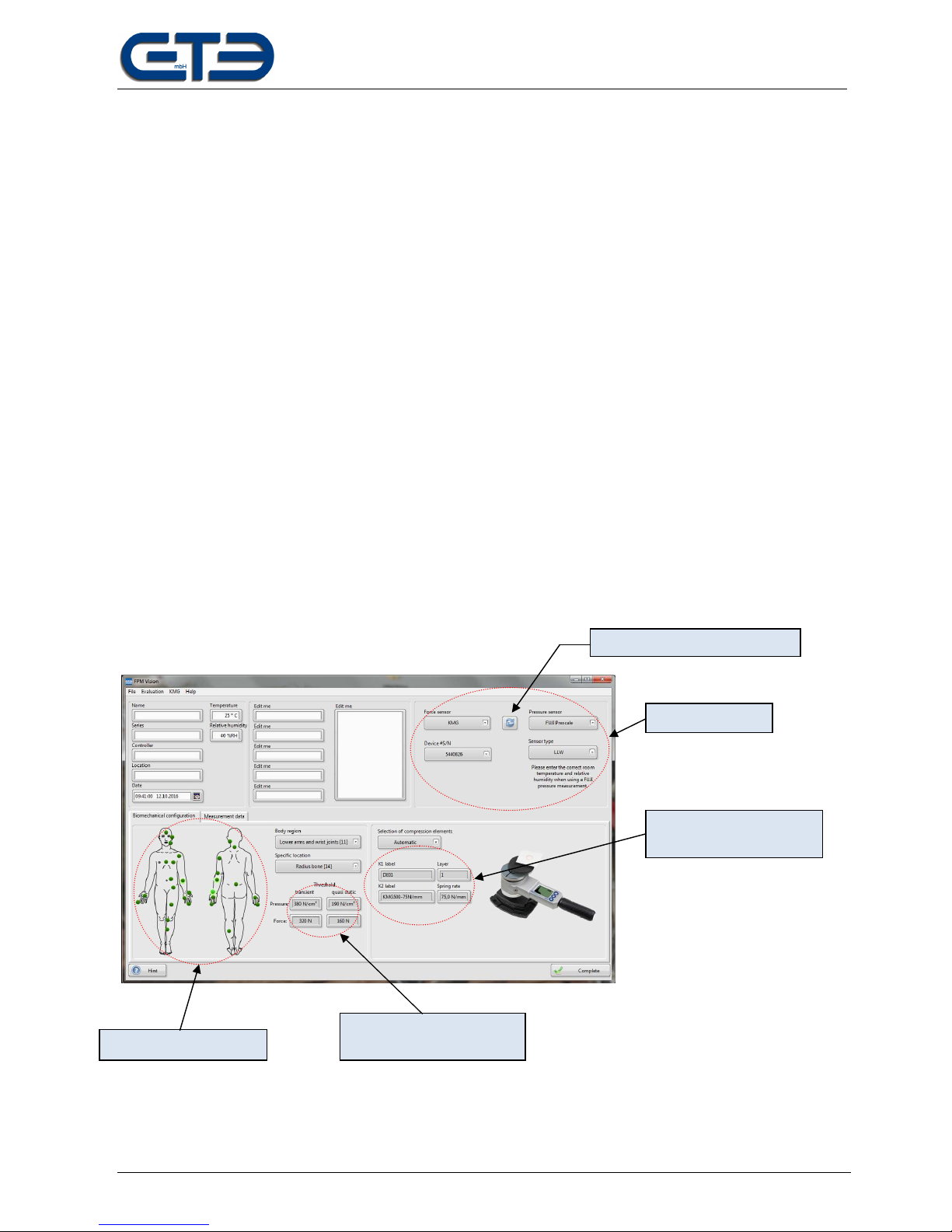
The software is designed for the visualization, analysis, editing, and archiving of force measurements
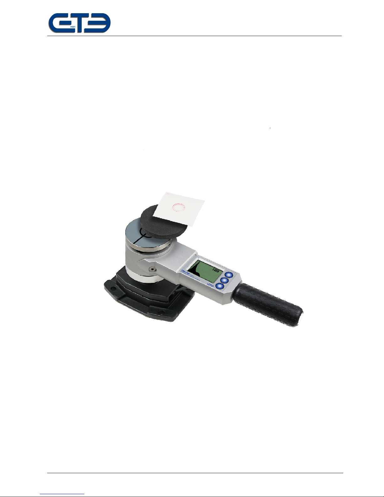
Recorded using the KMG 300-75 and KMG 500-75 measuring systems and of pressure images generated using
Fuji-Prescale films. The measurement method is used for determining impact and clamping forces at
collaborative robots based on ISO/TS 15066. It may only be used for this purpose.
The software specifies the configuration of compression elements on basis of the selected body region. It offers
an import function for printed images with automatic filtering and color calibration. It features an integrated report
generation for data archiving purposes.
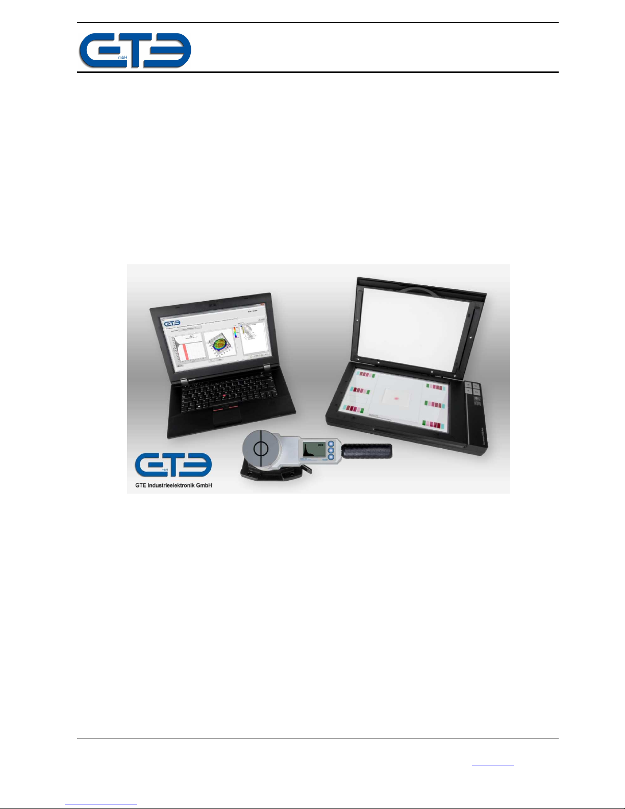
Scope of the system
•KMG 300 and/or KMG 500 force gauge
•Power supply: AC100-240V to DC5V
•Voltage converter DC12-24V to DC5V
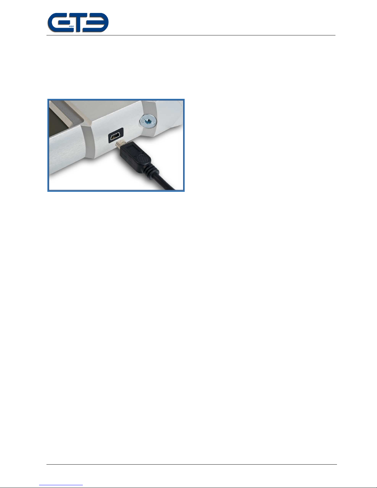
•USB-A to USB-B Mini cable
•Transport case for force gauge
•Compression elements K1
•USB stick with PC software FPM Vision
•Mounting base with adapter
•EPSON scanner V370
•Scanner power supply
•USB-A to USB-B cable
•Calibration element for scanner
•Fuji-Prescale film, 2-piece
FPM VISION software updates
Due to possible normative changes further updates may be necessary. You can find the current version of the
software on our homepage www.gte.de/downloads. We recommend visiting our webpage regularly and after
normative changes and checking the software for available updates.

GTE Industrieelektronik GmbH
Subject to technical changes FPM Vision – EN02 Page 3 of 15
Software license
The software is available in several configurations. The function modules are enabled using a license key. You
will receive a respective license key when purchasing the measuring gauge and software in your desired
configuration.
The license key is entered at the factory, when the device is shipped. After the installation, the software is ready
according to the purchased license.
An update, e.g., from “force analysis” to “force and pressure” analysis, is possible without returning the
measuring device. When purchasing the extended license, you will receive a new license key you can enter via
the “KMG\License” menu. For this purpose, the measuring device must be connected to the PC. Next, the device
can also be used at all other stations.
The PC software may be installed on 10 computers/stations. As soon as the KMG 300 or KMG 500 is
connected, the enabled functions can be used.
Installation of the FPM Vision software
System requirements: WIN7 or WIN 10, MS Word 7 or higher
•Unzip the software zip file (FPM Vision X.X) on your data carrier.
•Start file .\ Setup.exe
•Follow the installation instructions and install the software completely.
•You may be asked to install additional drivers.
•If asked, connect a KMG device with PC using the enclosed USB cable.
•Restart the computer.
•You can find shortcuts to the software on the desktop and in the start menu
•Install the driver of the EPSONV370 scanner (EPSON CD).
Support:
For a fast and effective response to your questions, access our website www.kolrobot.com/support via the
“Support” menu item under the “Help” menu. Here you can ask your question and send it to the correct contact.
Here you can also find a FAQ area with information to the most important questions.
Tip: The software screen contains a “Tip” button. Click it for tips on handling the software and for explanations of
diverse fields.

GTE Industrieelektronik GmbH
Subject to technical changes FPM Vision – EN02 Page 4 of 15
USB connection of the KMG
The force gauge features an USB connection for transferring the measured data of the KMG 300/500. In the
case of a complete installation, all necessary drivers are already on the PC. You can find further device
information in the respective operating instructions.
EPSON scanner with calibration element
The EPSON scanner of type V370 is required for the pressure analysis. The scanner properties are decisive for
a scan followed by pressure force analysis. An alternative scanner may only be used after previous consultation.
The enclosed calibration element must be used for every scan. It is necessary for the correct conversion of the
color intensities into pressure values. Make sure the alignment on the scanner is correct (details, see page 13).
The calibration element can fade due to light exposure or become damaged due to other circumstances. The
software checks the functionality of the calibration element and displays the status after scanning using 6
elements. The 6 elements must all be illuminated. If this is not the case:
- Check the calibration element and QR code for damage.
- If damage is present, the calibration element must be replaced.
- Check the scanner area for residues and contaminations.
- Clean the calibration element.
- Check the scanner functionality by scanning a full-area image as needed. Check for irregularities in the
color gradient. Irregularities indicate a defective scanner.
The calibration element is available as spare part from GTE GmbH.

GTE Industrieelektronik GmbH
Subject to technical changes FPM Vision – EN02 Page 5 of 15
Starting the software
The following shortcuts were installed during installation to start the software:
•'FPM Vision' desktop icon
•Start menu\ All programs\ FPM Vision \ FPM Vision
Menu overview
File menu:
New: New data report is opened.
Open: An existing analysis is opened.
Template from file: Loads the data from an existing analysis into a new data report
Storage path: Defines the superordinate folder for measured and report data.
Change language: Selection of the desired language.
Settings: The Settings menu is opened.
Exit: FPM Vision is exited.
Evaluation menu:
Generate report: Generates a new report from the completed measurement using
the current template.
Edit template: Opens the template file. Edits and saves the new template.
Rest template: Resets the current template to the standard.
csv Export: Compilation of several measurement data into a table in csv format.
KMG menu:
Export measurement data: Exporting the measurements from the KMG 300/500 into a csv file.
License: Inputting or changing the license key.
Help menu:
Manual: Download link for the operating instructions
Support: Opens our online support area.
Version information: Program version and information on sources.
GTE: Street address of GTE GmbH
Default settings – system configuration
After installation completion, the system is configured and ready for operation. The calculation basis for the
configuration of the measuring equipment is preset to the calculation basis according to the BGHM – Employer's
Liability Insurance Associations. The calculation basis can be changed as needed via the File\Settings menu
item.
Select the File\Settings menu to access the settings. The window displays the standard configuration settings for
the components. We recommend not changing the standard settings.

Subject to technical changes
Typical measuring setup
To ensure a correct force and pressure
according to the configuration specifications. For recording the force profile, the KMG 300/500 must be firmly
secured, placed and aligned. The force application should be perpendicular to t
The required compression element is also secured on the measuring surface. Adhesive stripes attached to the
outside can be used for this purpose.
Furthermore, the Fuji-
Prescale film is cut to a suitable size and secured on the compr
This measuring setup is used for recording force and pressure. Also write down the measuring number on the
pressure image.
Information on the functionality of the Fuji
with the rolls.
GTE Industrieelektronik GmbH
FPM Vision – EN02
Typical measuring setup
To ensure a correct force and pressure
measurement, the measuring equipment must be selected and placed
according to the configuration specifications. For recording the force profile, the KMG 300/500 must be firmly
secured, placed and aligned. The force application should be perpendicular to t
he measuring surface.
The required compression element is also secured on the measuring surface. Adhesive stripes attached to the
outside can be used for this purpose.
Prescale film is cut to a suitable size and secured on the compr
This measuring setup is used for recording force and pressure. Also write down the measuring number on the
Information on the functionality of the Fuji
-
Prescale films can be found in the original Fuji instructions enclosed
GTE Industrieelektronik GmbH
Page 6 of 15
measurement, the measuring equipment must be selected and placed
according to the configuration specifications. For recording the force profile, the KMG 300/500 must be firmly
he measuring surface.
The required compression element is also secured on the measuring surface. Adhesive stripes attached to the
Prescale film is cut to a suitable size and secured on the compr
ession element.
This measuring setup is used for recording force and pressure. Also write down the measuring number on the
Prescale films can be found in the original Fuji instructions enclosed

GTE Industrieelektronik GmbH
Subject to technical changes FPM Vision – EN02 Page 7 of 15
Step 1: Configuring the measuring equipment
I. Create a new data report via the File\New menu. Connect the force gauge KMG 300/500 to the PC.
Select the force sensor and the pressure sensor in the top right area. The available sensors are
displayed for selection depending on the license. The serial number of the device is displayed indicating
the successful connection to the KMG 300/500. Important: Select the type of film used. An incorrect
selection will impact the measuring result!
II. Switch to the “Biomechanical configuration” tab and select the body region using the drop-down menu.
All body locations corresponding to the body region are shown on the body model. The numbers
correspond to the numbering of the standard.
III. Select the suitable measuring point using the “Specific location” drop-down menu. The selected point is
marked highlighted in green. Tip: You can also select specific locations per mouse click on the body
model.
IV. Next, the currently applicable thresholds for this collision point are displayed underneath the menu.
V. The compression element K1 to be used and the required spring rate are shown on the right side of the
window. For the KMG 300/500 force sensors, this rate is fixed. The compression elements are selected
automatically based on the preset calculation basis (see “Default settings – system configuration”).
VI. If – deviating from this – an alternative compression element is used, the setting can be changed from
“Automatic” to “Manual”. Different compression elements can then be selected using the then available
drop-down menus. Using the menus, the desired and available compression elements and springs can
be selected (only in connection with the “Piezo” force sensor type).
Sensor
selection
Compression element
and spring constant
Select body location Thresholds for body
location
Update after change

GTE Industrieelektronik GmbH
Subject to technical changes FPM Vision – EN02 Page 8 of 15
Step 2: Report data of the measurement
Additional fields for report data and parameters of your measurement are available in the top left area of the
window.
•Use descriptive names for the “Test series” and “Test name” fields. Directories with the same name
will be created in the storage path, when the measurement is saved!
•Enter the name of the tester.
•You can indicate time and location.
•Fields “Temperature” and “Relative humidity” are parameters and influence the presented
measurement result of the Fuji films! For this purpose, these values must be determined on site
using a suitable measuring device.
•The “Edit me” fields are used for further documentation, e.g., to specify diverse parameters, such as the
collision form or the name of the test object. Field headers can be edited and renamed by clicking on the
“Edit me” fields.
•Using the “File\Template from file” menu function, the content of an already stored measurement can be
imported. For this purpose, select the respective measurement zip file.
Input options for
measurement conditions.
Tip: The headers can be
renamed by clicking on
them.

GTE Industrieelektronik GmbH
Subject to technical changes FPM Vision – EN02 Page 9 of 15
Step 3: Importing measurement data
The KMG 300 and KMG 500 feature an integrated analysis and memory. After a measurement, the force profile
is displayed graphically. Furthermore, the results for static and dynamic/transient force can be read out directly
on the device's display. This way, measurements can be performed and analyzed on site independently from a
laptop/PC. The measurements are numbered and saved.
After all pressure measurements are completed, the data can be imported. Tip: Film can be numbered using a
pen or similar.
Note: if possible, the pressure measuring film should be imported immediately.
Preparation:
•Connect the KMG 300 or KMG 500 with the laptop/PC.
•Connect the scanner with the laptop/PC and switch it on.
•Place the pressure measuring film together with the calibration sheet onto the scanner (see notes page
13).
•Prior to importing the pressure data, check once more that the correct film type is set and that
the temperature and air humidity data is correct!
Import:
Switch to the “Measurement data”
tab for importing. The memory data
of the force gauge is automatically
loaded.
By operating the “Force
measurement data import”
drop-down field, you can load
the desired measurement from
the KMG. For this purpose,
the device must remain
connected.
After selection of the force
measurement, the
corresponding pressure
measurement can be
imported. For this purpose,
press the “Scan” button.
Select scanner V370.
Scanning starts.

GTE Industrieelektronik GmbH
Subject to technical changes FPM Vision – EN02 Page 10 of 15
Import:
Next, the scan is displayed.
Press and hold the left mouse
button and select the relevant
area.
Confirm with “OK”.
•The pressure image is imported
and filtered. The evaluated result
is displayed in the right window.
•Measuring points can be added to
the pressure image as needed.
For this purpose, right-click on the
desired point. Select “Add note” in
the menu. Left-click on the text
and drag the text field onto the
desired position.
•Force measurement and pressure
image can be newly loaded as
needed. At this point in time, the
measurement has not been saved
yet.
Once all data is correct, click on the
“Complete” button. The measurement
data is now saved in the folders. Next,
the “Results and thresholds” window
opens.
After scanning, check that
all color fields of the
calibration element were
recognized. If this is not
the case, check the
calibration element!

GTE Industrieelektronik GmbH
Subject to technical changes FPM Vision – EN02 Page 11 of 15
Step 4: Measurement results and thresholds
After completion or after opening an existing measurement file, a separate window opens displaying the stored
results.
After a measurement is “completed”, directories are created based on the names in the “Test series” and “Test
name” fields (section “Step 2”). You can access the directory via the “Open measurement directory” button.
5 files are generated in the destination folder:
•A file with the raw data
•An image file of the force measurement
•An image file of the pressure measurement
•A Word report. The report is created based on a Word template (see below) and contains the configured
data fields and/or bookmarks. The Word document can be opened an edited. This way, a measurement
can be documented comprehensively.
•An image file across the scanned calibration element with the pressure measurement. This file can be
imported later as needed via the “From file” button in the configuration window.
Measurement
results
Thresholds of the specific
locations of the group and
measurement parameters.
The selection of the body
region shows the
respective thresholds in
the force diagram and the
3D view of the pressure
image.
Open the destination folder
with the generated files.
Open the report (Word file).

Subject to technical changes
Graph palette
Select the cursor function in the graph palette for a selective value determination. In the diagram for force
analysis, you can move the cursor on the left edge of the table using drag and drop. The values at the
cursor position are displayed when releasin
In the pressure distribution presentation, you can display the measurement value of a point. For this purpose,
left-
click on the desired point in the diagram.
Click on the “Zoom” menu and select one of the following functions
•
Zoom into an area of the graph
•
Zoom into an X
•
Zoom into a Y
•
Full view
•
Zoom in
•
Zoom out
csv Export
Batch analysis can be used to compile the parameters and results of measurements into a .csv file. Start
process via the “Evaluation\
csv Export
consider and compile all measurement data in this folder and its subfolders.
Save the file. Next, the files can be imported into MS Excel.
GTE Industrieelektronik GmbH
FPM Vision – EN02
Select the cursor function in the graph palette for a selective value determination. In the diagram for force
analysis, you can move the cursor on the left edge of the table using drag and drop. The values at the
cursor position are displayed when releasin
g the mouse button.
In the pressure distribution presentation, you can display the measurement value of a point. For this purpose,
click on the desired point in the diagram.
Click on the “Zoom” menu and select one of the following functions
Zoom into an area of the graph
Zoom into an X
-range of the graph
Zoom into a Y
-range of the graph
Full view
Zoom in
Zoom out
Batch analysis can be used to compile the parameters and results of measurements into a .csv file. Start
csv Export
” menu. You will be prompted to select a folder. The batch analysis will
consider and compile all measurement data in this folder and its subfolders.
Save the file. Next, the files can be imported into MS Excel.
GTE Industrieelektronik GmbH
Page 12 of 15
Select the cursor function in the graph palette for a selective value determination. In the diagram for force
analysis, you can move the cursor on the left edge of the table using drag and drop. The values at the
In the pressure distribution presentation, you can display the measurement value of a point. For this purpose,
Batch analysis can be used to compile the parameters and results of measurements into a .csv file. Start
the
” menu. You will be prompted to select a folder. The batch analysis will

GTE Industrieelektronik GmbH
Subject to technical changes FPM Vision – EN02 Page 13 of 15
Notes regarding the scanning process:
Place the Fuji Prescale pressure sample with the calibration sheet onto the scanner as shown below. Accurate
placement of the calibration sheet is important.
Sample centered on the scanner,
coarse side downward
Placement of the calibration
sheet – the sample must be
centered within the framed area
The calibration sheet must touch
the marked corner.
The edges of the calibration
sheet must not cross the scan
window

GTE Industrieelektronik GmbH
Subject to technical changes FPM Vision – EN02 Page 14 of 15
Creating a report template
Open the template via the “Evaluation\Create template” menu. You can control, which measurement data will be
displayed, by inserting or deleting bookmarks. Place your logo and address data. Insert text, such as
measurement execution instructions, and format the template. An overview of all possible bookmarks and their
names can be found below.
Bookmarks
Bookmark Function
Parameter1 ... Parameter6 Content of field (Edit Me) 1 … Content of field (Edit Me) 6
Parameterlabel1 ... Parameterlabel6 Header of field (Edit Me) 1 … Header of field (Edit Me) 6
Date Date
Humidity Rel. Humidity
Location Location
PressuredistributionTransient Pressure distribution
Forcediagramm orce diagram
PressuredistributionStatic Pressure distribution
Executor Tester
Series Series
Pressure axValue Pressure maximum, transient
Pressure axTime Pressure maximum time, transient
Force axValue orce maximum, transient
Force axTime orce maximum time, transient
Temperature Temperature
ForceStaticValue orce maximum, static
ForceStaticTime orce maximum time, static
PressureStaticValue Pressure maximum, static
PressureStaticTime Pressure maximum time, static
Time Time
SoftwareVersion Software version
easurement Measurement
K1 aterial K1 Material
K1Layer K1 Layer
K2SpringConstant K2 Spring const
K2Label K2 label
BodyRegion Body Region
ThresholdForceTransient Threshold force transient
ThresholdPressureTransient Threshold pressure transient
ThresholdForceStatic Threshold force static
ThresholdPressureStatic Threshold pressure static

GTE Industrieelektronik GmbH
Subject to technical changes FPM Vision – EN02 Page 15 of 15
K GSerialnumber KMG Serial number
K GType KMG Type
K GNumber KMG Measurement number
FUJICalSN Calibration element S/N
FUJIType ilm
SpecificBodyArea Specific Body area
SpecificBodyAreaNumber Specific Body area number
BodyRegionNumber Body Region number
AllThresholdForceTransient Threshold force transient
AllThresholdPressureTransien Threshold pressure transient
AllThresholdForceStatic Threshold force static
AllThresholdPressureStatic Threshold pressure static
SourceThresholds Source of the thresholds
AllSpecificBodyArea Specific Body area
AllSpecificBodyAreaNumbers Specific Body area number
FUJIQual ound Color fields
FUJIFilter ilter
TSType ilm Type
TSSN Serial number of the film
TSEquilibrationfile Equilibration file
TSSensitivity Sensitivity
TSHandleSN Serial number of the Handle
K GLowerforce Lower threshold of the force values
PiezoType Sensor Type
PiezoFrequency Measuring frequency
PiezoTriggerlevel Trigger level in N
PiezoPretrigger Data acquisition before trigger level
PiesoSN Serial number of the Logger
PiezoFilter ilter frequency of the force in Hz
Pressure3D ax Print image with transient limit value and maximum pressure
Pressure3Dstatic Print image with static limit value and static pressure
Warnings
Warning message
PressureError
Deviation of Pressure
ForceError
Deviation of force
This manual suits for next models
1
Table of contents
Other GTE Measuring Instrument manuals
Popular Measuring Instrument manuals by other brands

Endress+Hauser
Endress+Hauser EngyCal RH33 Brief operating instructions

ABB
ABB C11 user manual

CPN
CPN MC3 ELITE operating manual

Hanna Instruments
Hanna Instruments HI702 instruction manual

WATANABE ELECTRIC INDUSTRY
WATANABE ELECTRIC INDUSTRY WPMZ-1 Series Quick instruction manual

Tektronix
Tektronix TLA715 Series instructions

HIOS
HIOS HM-10 Operation manual

PANCONTROL
PANCONTROL PAN 180 CB-A operating manual

LOVATO ELECTRIC
LOVATO ELECTRIC DMED300T2MI instruction manual

Edwards
Edwards AIM-S-NW25 instruction manual

ACR Electronics
ACR Electronics Vecta 3 Product support manual

Smart Storm
Smart Storm Universal Smart Meter instruction manual