manuals.online logo
Brands
  1. Home
  2. •
  3. Brands
  4. •
  5. Gualala Robotics
  6. •
  7. Lighting Equipment
  8. •
  9. Gualala Robotics LIGHTRAIL 5 User manual

Gualala Robotics LIGHTRAIL 5 User manual

CONDITIONS OF OPERATION
Adjusting the LightRail 5.0 Commercial Drive variable time delay will be up to you, as all gardens are different. We suggest first setting the delay to 30 sec-
onds. Then after observing your plant growth you may want to change the length of delay. A longer delay would dictate more light on the ends and less in
the middle. A shorter delay would have the opposite effect.
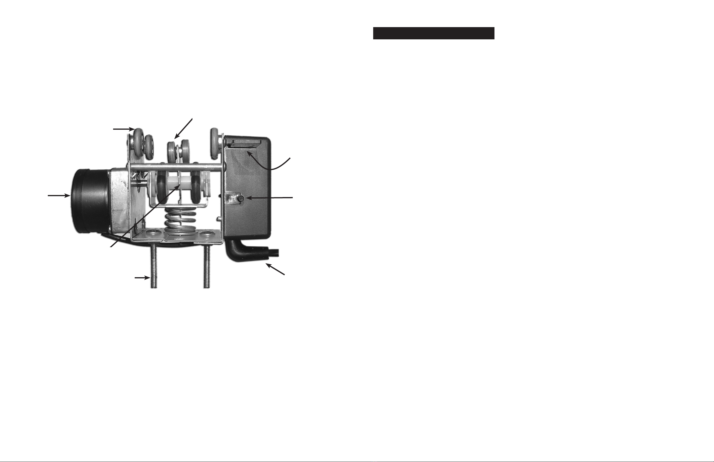
The first few weeks of operation will be the Drive Motor’s break-in period. The Trolley Wheels will turn gray as well as shed some nylon. The Drive Wheel’s
O-Ring may turn silver, and it too will shed some skin. These are both normal conditions as the moving parts of the Drive Motor conform to their respective
grooves of the Rail.
After several weeks of operation you may notice a slight pause as the Drive Motor starts up after changing direction, this is normal. It is the D Hole of the
molded Drive Wheel showing some wear and loosening up upon the Drive Motor’s shaft. Again this is normal and is a good thing as it will allow the Drive
Wheel to self adjust upon the Motor’s shaft. As for the pause when the Drive Motor changes direction, this also is normal and beneficial. It will reduce the
load on the gear train while changing direction.
It is a good idea to use a timer on the Drive Motor. After all, the lamp need not be moving when the lights are out. This period of off time adds up, and
will greatly reduce wear on the Drive Motor.
You should wipe the Rail off with a dry cloth from time to time. If cleaning the Rail becomes necessary use rubbing alcohol or window cleaner. Never use
any petroleum or wax based substance on the Rail or the rubber Drive Wheel.
If Drive Wheel slippage should ever become an issue, it is OK to clean the Drive Wheel’s rubber tires. Again use rubbing alcohol or window cleaner. Never
use any petroleum or wax based substance on the Rail or the rubber Drive Wheel.
LIGHTRAIL *5.0 LIMITED LIFETIME WARRANTY
A. Gualala Robotics Inc. warrants this LightRail 5.0 Drive Motor to be free from defects in materials and workmanship for its usable lifetime. Gualala
Robotics Inc. will repair or replace such product or part thereof which, upon inspection by Gualala Robotics Inc., is found to be defective in materials or
workmanship. This lifetime warranty is limited to non serviceable items only and does not include drive and trolley wheels. As a condition to the obligation
of Gualala Robotics Inc. to repair or replace such product, the product must be returned to Gualala Robotics Inc. together with proof-of-purchase satisfac-
tory to Gualala Robotics Inc.. This warranty is non-transferable.
B. The proper Return Authorization Number must be obtained from Gualala Robotics Inc. in advance of return. Call Gualala Robotics Inc. at 970-761-2596 to
receive the Return Authorization Number to be displayed on the outside of your shipping container.
You must send your dated sales receipt along with a written statement setting forth the name, address, and daytime telephone number of the owner,
together with a brief description of any claimed defects and the drive unit to Gualala Robotics, Inc., 5158 Parfet Street, Unit 3 Wheat Ridge, CO 80033. You
must pay shipping to the factory. After repair or replacement of your drive unit, Gualala Robotics will ship it back at no charge. Parts or product for which
replacement is made shall become the property of Gualala Robotics Inc..
Gualala Robotics Inc. shall use reasonable efforts to repair or replace any LightRail 5.0 Drive Motor covered by this limited warranty within fifteen days of
receipt. In the event repair or replacement shall require more than fifteen days, Gualala Robotics Inc. shall notify the customer accordingly. Gualala Robotics
Inc. reserves the right to replace any product which has been discontinued from its product line with a new product of comparable value and function.
This warranty shall be void and of no force of effect in the event a covered product has been modified in design or function, or subjected to abuse, misuse,
mishandling or unauthorized repair. Further, product malfunction or deterioration due to normal wear is not covered by this warranty.
GUALALA ROBOTICS INC. DISCLAIMS ANY WARRANTIES, EXPRESS OR IMPLIED, WHETHER OF MERCHANTABILITY OF FITNESS FOR A PARTICULAR USE,
EXCEPT AS EXPRESSLY SET FORTH HEREIN. THE SOLE OBLIGATION OF GUALALA ROBOTICS INC. UNDER THIS LIMITED WARRANTY SHALL BE TO REPAIR
OR REPLACE THE COVERED PRODUCT, IN ACCORDANCE WITH THE TERMS SET FORTH HEREIN. GUALALA ROBOTICS INC. EXPRESSLY DISCLAIMS ANY LOST
PROFITS, GENERAL, SPECIAL, INDIRECT OR CONSEQUENTIAL DAMAGES WHICH MAY RESULT FROM BREACH OF ANY WARRANTY, OR ARISING OUT OF THE
USE OR INABILITY TO USE ANY GUALALA ROBOTICS INC. PRODUCT. ANY WARRANTIES WHICH ARE IMPLIED AND WHICH CANNOT BE DISCLAIMED SHALL
BE LIMITED IN DURATION TO A TERM OF ONE YEAR FROM THE DATE OF ORIGINAL RETAIL PURCHASE.
Some states do not allow the exclusion or limitation of incidental or consequential damages or limitation on how long an implied warranty lasts, so the
above limitations and exclusions may not apply to you. This warranty gives you specific legal rights, and you may also have other rights which vary from
state to state. Gualala Robotics Inc. reserves the right to modify or discontinue, without prior notice to you, any model or style LightRail 5.0 Drive Motor.
If warranty problems arise, or if you need assistance in using your LightRail 5.0 Drive Motor contact:
Gualala Robotics Inc. Tel: 970-761-2596
5158 Parfet Street, Unit 3 Fax: 970-879-6660
Wheat Ridge, CO 80033
NOTE: This warranty is valid to U.S.A. and Canadian customers who have purchased this product from an authorized Gualala Robotics Inc. dealer in the
U.S.A. or Canada. Warranty outside the U.S.A. and Canada is valid only to customers purchased from a Gualala Robotics Inc. international distributor or
authorized Gualala Robotics Inc. dealer in the specific country and please contact them for any warranty service
*TM PATENTED
REPLACEMENT PARTS
Like all moving mechanical objects, parts wear out. e.g. your new car will need new brakes and tires someday. At some point in time your Drive Motor
will need some parts as well. As not all LightRail *5.0 dealers stock these parts, you may want to order them today, so you will have them on hand when
needed.
Gualala Robotics Inc. offers a trolley wheel replacement for sale direct from the factory. It contains two (2) Inner Drive Trolley Wheels as well as four (4)
Outer Trolley Wheels. This trolley wheel replacement sells for $29.95. If you are interested, simply fill out the form below and send it and a money order
payable to Gualala Robotics. We will fill your order promptly. Sorry, no C.O.D. or checks; credit card orders should visit www.lightRail5.com
Gualala Robotics, Inc. offers refurbish services for non-warrantable drive motors and a range of refurbished motors and part kits at www.lightRail5.com. If
you have an older LightRail 3.0 or 3.5 and it is not working or not working to expected standards. Go to LightRail3.com for details.
REPLACEMENT PARTS ORDER FORM
Please send me ______ LightRail 5.0 Trolley Wheel Replacement @ $29.95 (U.S. dollars) each. Included is my money order payable to Gualala Robotics.
NAME
ADDRESS
CITY STATE ZIP
IMPORTANT SAFETY INSTRUCTIONS
Manufactured by Gualala Robotics, Inc., PO Box 774288 Steamboat Springs, CO 80477 USA. *FOR USE WITH GROW LAMPS THAT
ARE U.L. LISTED AND / OR C.S.A. CERTIFIED.* RISK OF FIRE AND ELECTRICAL SHOCK, THIS PRODUCT REQUIRES PROPER FIELD
WIRING AND IS INTENDED TO BE INSTALLED BY A QUALIFIED ELECTRICIAN ONLY. A SURGE PROTECTOR SHOULD BE INSTALLED.
Please read these instructions and the operating instructions before installing your unit. The instructions supplied with your
unit contain important information. Review all documentation before installing your unit.
1. Dropping this unit will cause serious damage to it.
2. Straight and secure Rail mounting is essential for both safety and operation. Refer to STEP TWO of the
mounting instructions inside.
3. If you are using chain and/or hooks to hang your grow light from the drive unit, be sure they are load rated to handle
the weight of your grow light.
4. This unit is rated for use on specific voltage identified by a label fastened to your unit. Never use this unit on a different
voltage than specified.
5. Your unit is equipped with a 3-wire grounding-type electrical plug. This unit will only fit into a grounding-type outlet
and is a safety feature. DO NOT DEFEAT THE GROUNDING CONNECTION. If you are unable to insert the plug into an
outlet, call an electrician to replace the obsolete electrical outlet.
6. After installation, be sure there is plenty of slack in power cords as described in STEP FIVE of instructions.
7. The electrical portion of this unit is non-serviceable. Do not attempt to remove the switch box cover under any circum-
stances. If unit fails to operate due to an electrical malfunction, unplug, remove from Rail and return to manufacturer.
8. Always unplug unit if: you are adjusting grow light height; removing Drive Unit for service; or any procedure. A moving
grow light warrants danger.
9. WARNING: Never wire/hook this unit to your lamps/lights ballast, it will cause damage to the motors circuitry.
www.LightRail5.com
LR5
Switch
Accuator
Time Delay
Adjustment
Knob
Motor
Carrier
Wheels
Drive Trolley
Wheels
Drive Wheel
Assembly
1/4” Crossbar
Hanging Screws
Assembly Tools Required
Phillips head screwdriver, tape measure, chalk line or string, drill,
phillips driver bit, 1/8’’ drill bit, 7/16” wrench, pliers.
Powercord
LIGHTRAIL 5
INSTALLATION INSTRUCTIONS
STEP FIVE: HANGING LIGHTS
At this time you can remove the yellow tag and wire tie on the Drive Motor.
Now you’re ready to hang your lights, and below are some suggestions for doing so.
As you hang the first light, the unit will become very unbalanced and tip to one side.
Don’t worry about it and just be careful. Just know that it will even out when you hang
the second light. Or if another person is available, they can hold the opposite end while
you hang the first light. We do not recommend trying to hang both lights simultaneously.
We’ve tried. It does not work very well.
Ridged mounting lights to the crossbar is not recommended. Many horizontal reflectors
incorporate wire vee hooks. We recommend using them or using chains and hooks to
allow for lamp height adjustment.
Running the cords can be a cumbersome task. It is important that the Drive Motor can
travel its full distance to both ends without restriction from the cords.
Some say it is best to bring the cords in from the side rather than bringing them in from
the end. After bundling the cords together, run the system down to both ends to find the
correct fastening point of the cords. Then fasten them to the ceiling or the wall leaving
enough slack so the Drive Motor can travel its full distance to both ends without restric-
tion
Things to check before operation.
1. Straight, level and secure Rail mounting is essential for both safety and
operation. Please be sure of this.
2. Make sure the switch stop eye screws are tight and make contact with the
Drive Motor’s switch actuator.
3. Be sure the lamps are hung securely from the crossbar
4. If the crossbar is not level, you can adjust the wing nuts to help level the bar.
5. Be sure the Drive Motor can travel its full distance to both ends without
restriction from the cords.
6. Be sure the yellow tag and wire tie have been removed from the Drive Motor.
Start by inserting the 2 crossbar ends into the cross-
bar splint.
Next align the holes in the crossbar splint with the holes
in the crossbar. There are 3 holes in each side of the
splint to accommodate different crossbar widths. You
must use the same holes in each side so the crossbar
ends span an equal distance from the center of the
splint (Fig 4-1).
After inserting the 2 crossbar ends into the crossbar
splint secure them using the 2 - 1/4” x 1 1/2” crossbar
to splint screws and 2 of the 1/4” hex nuts (Fig 4-2).
Next install the 4 - lamp hanging eye screws with the
remaining 1/4” hex nuts (Fig 4-3). There are two sets
of holes on each end to accommodate different light
widths. Note: As in the LightRail 5 logo you can see
the crossbar ends are bent. If you have a particularly
high ceiling you may want to hang the crossbar with
the bends down opposite the logo. This you will need
to decide so the 1/4” eye screws are mounted facing
the right way.
Now that the crossbar is assembled it can be mounted
to the Drive Motor. Locate the 2 holes in the center of
the crossbar splint. Slide them over the two 1/4” screws
protruding from the bottom of the Drive Motor and fas-
ten it using the 2 - 1/4” wing nuts (Fig 4-4). Be sure
to tighten the wing nuts until the 1/4” screws on the
bottom of the Drive Motor begin to protrude from the
bottom of the wing nuts (Fig 4-4).
STEP FOUR: INSTALLING THE CROSSBAR
4 - Lamp Hanging
Eye Screws
1 - Crossbar splint
2 - 1/4” Wing Nuts
2 - Crossbar ends
2- 1/4” x 1 1/2”
Crossbar to Splint Screws
10 -1/4” Hex Nuts
Tools you will need: 7/16” wrench, pliers
Fig 4-1
Crossbar Width Adjustment Holes
Fig 4-4
Fig 4-3
Fig 4-2
STEP ONE: RAIL ASSEMBLY
Start by matching ends of Rail halves
with arrows. While making sure the
alignment pins line up with their cor-
responding holes, push the two Rail
halves together (Fig 1-1); if needed
you can tap the Rail end on the floor to
assist in pushing the Rail halves all the
way together (Fig 1-2).
Next insert one slide nut in the slide nut channel
on each side of the Rail. Push them towards the
middle until they cover the joint where the 2 Rail
halves meet (Fig 1-3).
Last slide the Rail coupler over the top of the Rail and start each of the 4 - #10 machine
screws into the threaded holes in the slide nuts (Fig 1-4). Tighten them just until they are
snug, then stand the Rail on its end and torque the screws tight while pushing down on the
Rail (Fig 1-5).
Tools you will need: Phillips head screwdriver
1 - Rail Coupler 2 - Slide Nuts
2 - Rail Halves 4 - #10 x 3/8”
Machine Screws
Fig 1-3
Fig 1-5
Fig 1-4
Fig 1-2
NOTE: If you are mounting to a finished ceiling you must locate the joist beneath the drywall and
mount to it. Never mount Rail hanging brackets into drywall only. Also, we do not recommend
using drywall anchors for mounting into drywall material. In addition, if you are mounting to joist
under drywall you must use screws longer than the ones provided.
You will be using the 3 Rail hanging
brackets, 6 slide nuts and 6-#10 machine
screws to hang the Rail. Refer to Diagram
A for the Rail hanging bracket locations.
It may be best to mount the assembled Rail to a board and then mount that assembly above
your garden; a good wood for this method is 1”x 6”x 10 foot pine or cedar. Either can be found
at your local lumber store in ten foot lengths.
If you will be mounting the Rail in line on a ceiling
joist, the Rail will need to be hung after the board
is mounted to the joist. However it is easier to first
mount the Rail hanging brackets to the board.
Before mounting the Rail to the Rail hanging brack-
ets, slide the remaining 8 slide nuts into the slide nut
channel on the Rail. 4 on each side, 2 from either
end as the slide nuts can not pass by the middle of
the Rail because of the coupler.
Warning: straight, level and secure Rail mounting is essential for both safety
and operation. Mounting the Rail should be done by a capable person. If you
need help, we recommend hiring a carpenter.
STEP TWO: HANGING YOUR RAIL Tools you will need: Tape measure, chalk line or string,
drill, phillips driver bit & 1/8’’ drill bit.
10 - Slide Nuts
3 - Rail Hanging Brackets 6 - #10 x 1”
Wood Screws
Start by plugging the Drive Motor into its rated (check Drive Motor label) VAC power source.
Next pay close attention to the Drive Motor’s drive wheel assembly located in the center of
the Drive Motor (Fig 3-1). With the motor running and the switch actuator in the forward posi-
tion, line the small white trolley wheels up with the
corresponding square channel in the center of
the Rail. Gently push the drive wheel assembly
towards the Rail and it should drive itself onto the
Rail (Fig 3-1). If it won’t drive itself onto the Rail,
check that the switch actuator is in the forward
position, (pushed towards the Rail).
Now that the Drive Motor has driven itself onto
the Rail, unplug it and install the switch stop eye
screws. If you would like the Drive Motor to travel
the full length of the Rail, install them in the remain-
ing slide nut screw holes next to the Rail hanging brackets at the ends of the Rail. If you desire
a shorter travel distance you can use the remaining unused slide nuts
installed before you hung the Rail (Fig 2-1 and 2-2) and slide them to
any desired location. Make sure you install the switch stop eye screws
on the same side of the Rail as the switch actuator on the Drive Motor,
and tighten them until the eye of the screw is vertical so the switch
actuator will make contact (Fig 3-2).
STEP THREE: INSTALLING DRIVE MOTOR AND SWITCH STOPS
1 - Drive Motor 2 - Switch Stop
Eye Screws
IMPORTANT: You must allow the
Drive Motor to drive itself onto the
Rail, as it is impossible to push
the Drive Motor onto the Rail.
Diagram A
6 - #10 x 3/8
Machine Screws
Line small white trolley wheels with center channel
Fig 3-1
Note: Remember to install the adjustable switch
stop slide nut into Rail channel prior to mount-
ing as the slide nut can not pass the mounting
hardware on the end once installed.
fig 2-1
Then, slide the Rail into the Rail hanging brackets and fasten them to the slide nuts closest to
the ends as well as the slide nuts that line up with the center Rail hanging bracket using the
remaining #10 machine screws. When you’re finished hanging the Rail it must be mounted
by one bracket on each end and one bracket in the middle near the coupler. Additionally there
should be 1 unused slide nut on each side of the Rail, either left or right of the coupler. These
can be used for adjustable switch stops if desired (Fig 2-1 and 2-2).
Fig 2-2 Fig 2-2
Rail Hangers
Fig 3-2
Adjustable Switch Stop Slide Nut
End Switch Stop Position

Popular Lighting Equipment manuals by other brands

DARAY SL180LED manual

DARAY

DARAY SL180LED manual

Leding XPRESSION 250RGBLA user manual

Leding

Leding XPRESSION 250RGBLA user manual

IKEA LEDLJUS 803.574.54 manual

IKEA

IKEA LEDLJUS 803.574.54 manual

Sygonix 2361025 operating instructions

Sygonix

Sygonix 2361025 operating instructions

NVision NV1073KB owner's manual

NVision

NVision NV1073KB owner's manual

Inter-fab Zoomerang installation manual

Inter-fab

Inter-fab Zoomerang installation manual

PR Lighting XPar 150 Zoom manual

PR Lighting

PR Lighting XPar 150 Zoom manual

Rocky's Junior Assembly instructions

Rocky's

Rocky's Junior Assembly instructions

Coopers of Stortford G712 Instructions for use

Coopers of Stortford

Coopers of Stortford G712 Instructions for use

WAC Lighting WTK-6010 Series Installation instruction

WAC Lighting

WAC Lighting WTK-6010 Series Installation instruction

EuroLite LED TMH-21.i Twin Moving-Head Beam user manual

EuroLite

EuroLite LED TMH-21.i Twin Moving-Head Beam user manual

TIME LED Prestige Pro Installation and operating instructions

TIME LED

TIME LED Prestige Pro Installation and operating instructions

Feniex QUAD 1X DASH LIGHT instruction manual

Feniex

Feniex QUAD 1X DASH LIGHT instruction manual

GlacialLight GL-SP15-WW user manual

GlacialLight

GlacialLight GL-SP15-WW user manual

Arturo Alvarez Tina TN03 instructions

Arturo Alvarez

Arturo Alvarez Tina TN03 instructions

Sealey ML36110T instruction manual

Sealey

Sealey ML36110T instruction manual

JABSCO 62040-4 Series manual

JABSCO

JABSCO 62040-4 Series manual

Fotodiox PopSpot Ultra 100 user manual

Fotodiox

Fotodiox PopSpot Ultra 100 user manual

manuals.online logo
manuals.online logoBrands
  • About & Mission
  • Contact us
  • Privacy Policy
  • Terms and Conditions

Copyright 2025 Manuals.Online. All Rights Reserved.