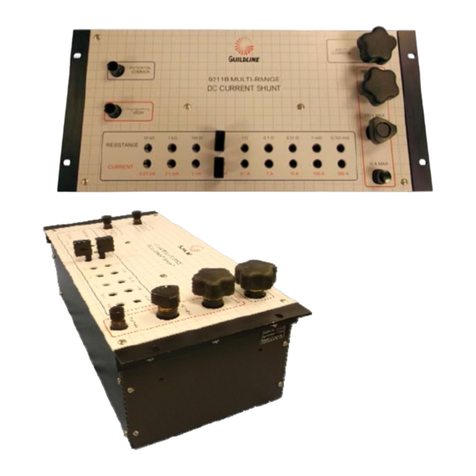
Guildline 9711B Series User manual

Model 9711B Series
Multi-Tap DC Current Shunt
Technical Manual
NOTICE
The contents and information contained in this manual are proprietary to
Guildline Instruments Limited. They are to be used only as a guide to the
operation and maintenance of the equipment with which this manual was
issued and may not be duplicated or transmitted by any means, either in whole
or in part, without the written permission of Guildline Instruments Limited.
TM9711B-A-00
6 November 2013


TM9711B-A-00
6 November 2013
i
Table of Contents
1.0 Introduction 1-1
1.1 Warranty 1-1
1.2 To ObtainWarrantyorCalibrationandRepairService 1-2
1.2.1 USAWarrantyReturnAddress 1-2
1.2.2 ReturnsAllOtherCountries 1-3
1.3 SafetyInformation 1-3
2.0 9711BSpecifications 2-1
2.1 UncertaintySpecifications 2-1
2.2 GeneralSpecifications 2-1
3.0 Overviewofthe 9711B 3-1
3.1 General 3-1
3.2 OperatingInstructions 3-1
3.2.1 MaximumCurrent 3-1
3.2.2 CurrentInputTerminals 3-2
3.2.3 RangeSelectorPlugs 3-2
3.2.4 PotentialTerminals 3-3
3.2.4 10AmpereMeasurementsandBelow 3-3
3.2.5 Measurements above10Ampere 3-3
3.2.6 mVOutput 3-4
3.2.7 FullRatedAccuracy 3-4
3.2.8 Minimumaccuracy 3-4
3.3 AdditionalApplicationsoftheModel9711B 3-5
4.0 Calibrationand PerformanceVerification 4-1
4.1 Introduction 4-1
4.2 CalibrationOverview 4-1
4.3 CalibrationIntervalandPerformance 4-1
4.4 EquipmentandStandardsRequiredforCalibration 4-2
4.5 RoutineCalibration 4-3
4.6 NominalValueCalibrationProcedure 4-5
4.6.2 Calibrationof0.01mA(10k )Rangesto1A(0.1 Ranges) 4-5
4.6.3 Calibrationof1 A (100m )Range 4-5
4.6.4 Calibrationof10 A (10m )Range 4-6
4.6.5 Calibrationof100A(1m )Range 4-6
4.6.6 Calibrationof300A(0.333333m )Range 4-6
4.7 OptionalCalibrationProcedure(DriftVerification) 4-10
4.7.1 Calibrationof300A(0.333333m )Range 4-10
4.7.2 Calibrationof100A(1m )Range 4-10
4.7.3 Calibrationof10 A (10m )Range 4-11
4.7.4 Calibrationof1 A (100m )Range 4-11
4.7.5 Calibrationof0.1A andbelow(1 )Ranges 4-12
TM9711B-A-00
6 November 2013
iii
LIST OF FIGURES
Figure3-1:9711BCurrentTerminalConnections 3-1
Figure3-2:9711BCurrentTerminalConnections 3-2
Figure3-3:RangeSelectorPlugs 3-2
Figure3-4:PotentialTerminals 3-3
Figure5-1:9711BSchemticOverview 5-6
LIST OF TABLES
Table4-1:ListofRecommendedTestCurrentsorVoltagesForResistance Values 4-4
Table4-2: 9711BNominalCalibrationDataWorksheet 4-8
Table4-3: 9711BOptionalCalibrationDataWorksheet 4-13

Section 1
TM9711B-A-00
6 November 2013
1-1
1.0 INTRODUCTION
This manual provides an overview of the 9711B DC Multi-Tap Current Shunt and also contains the
necessary information required to perform a calibration or verification test. General product
information,productdescriptionandperformancespecificationsarealsoincluded.
The phone number in the USA and Canada to obtain Product Support, Calibration Service or
ReplacmentPartsis(800)310-8104.
TocontactGuildlineInstruments,thefollowinginformationisprovided.
USAandCanadaTelephone: (613)283-3000
USAandCanadaFax:1-613-283-6082
OutsideUSandCanadaTelephone: +[0][1]613283-3000
OutsideUSandCanadaFax: +[0][1]613283-6082
YoucanalsocontactGuildlineInstrumentsLimtedviatheirEmail orWebsites.
Emailis: sales@guildline.com
Websiteis: www.guildline.com
1.1 Warranty
Guildline Instruments warrants its products to be free of defects in manufacture and normal
operation for a period of two (2) years from the date of purchase, except as otherwise specified. This
warranty applies only in the country of original purchase and only to the original purchaser, who is
also the end user. Equipment, which is defective or fails within the warranty period, will be repaired
orreplacedatourfactorywithoutchargeatthediscretionofGuildlineInstruments.
In addition, systems engineered by Guildline Instruments are warranted to be free of defects in
overall system operation for a period of two (2) years from the date of receipt by the original
purchaser.
Third party system components purchased by Guildline carry the warranty of the original equipment
manufacturer and will be accepted for claim by Guildline Instruments at our factory only after
warrantyauthorizationbytheoriginalmanufacturer.

Section 1
TM9711B-A-00
6 November 2013
1-2
LimitationofWarranty
Warranty coverage does not apply to equipment which has failed due to misuse, neglect, accident or
abnormal conditions of operation or if modifications or repairs have been made without prior
authorizationofGuildlineinstruments.
Temperatureprobesarenotwarrantedagainst failureduetomechanicalshock.
Fuses,lampsandnon-rechargeablebatteriesarenotwarrantedagainstbreakage.
DamageinShipmenttoOriginalPurchase
Instrument(s) should be thoroughly inspected immediately on receipt for visible damage. Any
damage should be reported to the carrier and further inspection and operational tests should be
carried out if appropriate to determine if there is internal damage. Contact Guildline Instruments
beforereturningforrepair. The customerorpurchasermustcomplete allfinalclaimswiththecarrier.
Regular charges will apply to non-warranty service. External service charges and expenses will be
billedatcostplushandling.
1.2 To Obtain Warranty or Calibration and Repair Service
Returns and/or Calibration and Repair Service Requests. Telephone, Fax and email addresses to
contactGuildlineareprovidedpreviously.
Guildline Instruments will pay for all warranty costs including shipping to and from the original
shipmentpoint. However,if the instrumentis purchased within one country and shipped to another,
Guildlinewillonlypay forshipping toand fromtheoriginalshiptocountryor customerpoint.
1.2.1 USA Warranty Return Address
USA Customers should use the following address to return instruments for warranty service or
calibrationsupport.
Guildline Instruments Limited
C/O AN Deringer
800 Proctor Avenue
Ogdensburg, NY 13669
Mark on the outside of the box:
RMA # _____________
Model#_____________
Serial#_____________

Section 1
TM9711B-A-00
6 November 2013
1-3
1.2.2 Returns All Other Countries
Forallothercountries,includingCanadapleaseshipto:
Guildline Instruments Limited
21 Gilroy Street, PO Box 99
Smiths Falls, ON K7A 4S9
Mark on the outside of the box:
RMA # _____________
Model#_____________
Serial#_____________
1.3 SafetyInformation
WARNING: During usage and calibration high voltages or high currents may be
present. Use caution when working above 40 Volts DC or currents above 1mA. Such
voltagesorcurrentscancausedeath.
The 9711B DC Shunts are designed to work within operating specifications. Applying more than the
recommendedcurrentwilldamagetheunit.
Inspect the 9711B for damage such as cracked connectors prior to use. If the unithasa burned smell
orsmokeisvisibleduringuse,discontinueuse immediately.
If testequipmentusedwith DC Shunts overloads or trips, this couldbe a sign that the 9711B requires
repair.
Inspect all test leads used with the Multi-Tap DC Current Shunt for damaged insulation or exposed
metal. Checkalltestleadsforcontinuity.
Ensurealltestleadsare correctlyconnectedpriortoapplyingcurrentorvoltage.
DonotuseMulti-tapDCCurrentShuntsaroundexplosivegas,vaporor dust.

Section 2
TM9711B-A-00
6 November 2013
2-1
2.0 9711B SPECIFICATIONS
2.1 Uncertainty Specifications
The specifications apply from Full Rate Current down to 10 % of the full rated current. For example the
300 A Range can be used from 300 A down to 30 A or the 100 A Range can be used down to 10 A.
Ensurecurrentcablesused canhandlethefullrated current.
Resistance
( )
FullRated
CurrentRange
(A)
1YearAccuracy1,2
(%)
Temperature
Coefficient
( /0C)
PowerDissipation
atRatedCurrent
(mW)
10,000
0.0001
±0.01
5
0.001
1,000
0.0001
±0.01
5
0.01
100
0.001
±0.01
5
0.1
10
0.01
±0.01
5
1
1
0.1
±0.01
5
10
0.1
1
±0.01
10
100
0.01
10
±0.01
10
1000
0.001
100
±0.05
30
10W
0.000333 333
300
±0.1
30
30W
Note1: Calibrated in air at 23 ± 1 oC referred to the unit of resistance as maintained by a National Metrology Institute, and expressed as a
deviationfromnominalwithatotaluncertaintyandcoveragefactorofk=2.
Note2: A traceable report of calibration stating the measured values and uncertainty is provided with each unit at test currents of 1/10 of
ratedcurrentandfullratedcurrenttoamaximumof100Aandaminimum of0.1mA,
2.2 General Specifications
GENERALSPECIFICATIONS
Environmental
Temperature
Humidity
Operating
5oCto38oC
40oFto100oF
<70% RHnon-condensing
Storage
-20oCto55oC
-40oF to131oF
<90% RHnon-condensing
ExteriorDimension(Rack
Mount)
222mm(H)
482mm(W)
183mm(D)
13.6kg
8.7" (H)
19"(W)
7.2" (D)
30 lbs

Section 3
TM9711B-A-00
6 November 2013
3-1
3.0 OVERVIEW OFTHE 9711B
3.1 General
The Model 9711B is a self-contained 9 range, 4 terminal shunt, for precision current measurements
up to 300 A. The design optimizes a number of important factors such as the effects of self-heating,
temperaturecoefficient,size,weight,easeofoperationandtotalmeasuringrange.
It provides wide range precise current measuring capability when used with a potentiometer or
digitalvoltmeterasareadout.
The shunt resistors are mounted in air to minimize size and weight, yet self heating is a negligible
source of error from 20 oC to 30 oC. Self-heating has only a small effect for a still wider range of
ambient temperatures. The resistors are made of selected zeranin wire and are non-inductively
wound, up to 1 ampere. The unit consists of nine (9) shunts, of the 4-terminal configuration. Each
shuntprovidesa 100 mVdrop at thenominal rated current. The maximum current rating is 140 % of
nominalforallrangesexceptthe100A and300Aranges,forwhichthemaximum is
110% of thenominalcurrentrating.
Figure3-1:9711BCurrentTerminalConnections
3.2 Operating Instructions
3.2.1 Maximum Current
Determine the maximum current that will be measured. If maximum current to be measured is
unknown, good instrumentation practice wouldbe to approximate it at a value thatis certain not to
beexceeded.
As an example, if the current is thought to be between 100 A and 120 A, then the connections
shouldmemadetothe300A terminalsforthemeasurement.

Section 3
TM9711B-A-00
6 November 2013
3-2
3.2.2 CurrentInputTerminals
The following terminals have the following rated currents. Note that all terminals should tighten
uniformlywhenmakingmeasurements. Looseconnectionscancausefaultyreadings.
Figure3-2:9711BCurrentTerminalConnections
3.2.3 Range Selector Plugs
Insert a pair of range selector plugs into the appropriate female receptacles on the front panel. One
plug is inserted over the other (in a vertical line). For example, if the range selected is 0.01 A, insert
the two plugs in the two receptacles directly over the engraved portion marked with the numeral
0.01A forcurrentand10 .
Figure3-3:RangeSelectorPlugs
Common (low) Connector - Used for all common inputs to 300 A and all ranges and
ALLrangeplugsettings.
300 A High Current Connector - Used for all High Current inputs to 300 A and ranges
plugssetto.33333
100 A High Current Connector - Used for all common inputs to 100 A and ranges
10 A and Lower Current Connector - Used for all common inputs to 10 A and ranges

Section 3
TM9711B-A-00
6 November 2013
3-3
3.2.4 Potential Terminals
Potential Terminalsare used forDMM orother measurementdevice
inputs to read the mV output produced at this terminal.. Use low
thermalsleadsforbestconnections.
Figure 3-4 : Potential Terminals
3.2.4 10 Ampere Measurements and Below
For measurements up to and including 10 A, connect the shunt in series with the power source
and the item under test. Note the polarity of the connections. If a DC ammeter is being calibrated
make sure the meter deflects up scale. If not, reverse its lead connections. Use leads of sufficient
size to carry the rated current. Connect leads to the two binding posts labeled "INPUT COMMON"
and "10 A MAX. Connect the milli-voltmeter being used as a readout instrument (DVM, DC
potentiometer, etc., with a range of 0 to 100 mV) to the two binding posts engraved Potential in
thespacebetweenthem.
Note 1: ·Polarity from the source is unimportant insofar as the shunt is concerned as long as the
potential and current connections agree, i.e., both "common" binding posts must be connected
inthesamepolarity.
Note 2: If the readout device is a low resistance milli-voltmeter, inaccuracies can result
proportional to the current drain. All potentiometers have a finite resistance so their use will
resultinsomelossofaccuracyduetocircuitloading.
If a DVM is employed, its input impedance should be checked to see that it is sufficiently high. Using
a DMM with 10 GΩimpedance could affect the verification of the 10 kΩup to 10 µΩ/Ω. On lower
ranges the impedance affect will be neglible. If using DVM with lower input impedance, careful
consideration of the setup is highly recommended. Consideration also should be for thermal emf
errors when using a less accurate DVM. This can be checked by checking the zero point and taking
2readingswiththecurrentreversedforthesecondreadingetc.
3.2.5 Measurementsabove10Ampere
For measurements above 10 A (up to and including 300 A), observe the same procedures as
described in 3 (a) above, except connect one lead to the 100 A or 300 A binding post as required
(instead of to the 10 A binding post). Be certain the range plugsare inserted into the correct range
positionsbeforeapplicationofthe testcurrent."

Section 3
TM9711B-A-00
6 November 2013
3-4
3.2.6 mV Output
Each shunt has a 100 mV output with the application of the rated current. In actual measurement, it
is this voltage or fraction thereof, which the readout instrument indicates. Its reading in mV is
directly proportional to the current applied. For example, if connections are made to the 10 A shunt,
a 100 mV reading indicates a 10 A flow within ±0.01 % (plus the accuracy of the readout
instrument). A 90 mV reading indicates a 9 A flow, etc. Direct readings in amperes can he obtained
for all ranges up to, and including, the 100 A range by arbitrarily fixing the decimal point of the
readout instrument. When making measurements using the 300 A range, readings must be
interpolatedasfollows:
TestCurrent(A)
ReadoutinmV
300A
(100±0.1)mV
270A
(90±0.09)mV
240A
(80±0.08)mV
210A
(70±0.07)mV
180A
(60±0.06)mV
150A
(50±0.05)mV
120A
(40±0.04)mV
90A
(30±0.03)mV
60A
(20±0.02)mV
30A
(10±0.01)mV
Onthe300Arange,toobtainareadinginamperes,theindicationofthemilli-voltmeterismultiplied
by3andthedecimalpointarbitrarilyfixed.
3.2.7 Full Rated Accuracy
Each shunt can be used at rated nominal current to full accuracy with no duty cycle limitations. For
the100Aand300Aranges,30minutesto1hminimumshouldbeallowedforthemeterreadingsto
settletoduetothermaldissipationeffects.Allotherrangesshouldbestablewithin15minorless
Note: If an overload has inadvertentlybeen applied, for best accuracy allow the shunt to cool for
approximately 1 h before using again. It is good instrumentation practice to reduce power to
zerobeforedisconnectingtheshunt.
3.2.8 Minimumaccuracy
Minimum accuracy that can be attained overall is the accuracy of the shunt resistor in use plus the
accuracy of the readout instrument. This value is in "± % of full scale" and "± % of reading"
depending on how the readout instrument is rated. As an example. using a DVM with ± 0.006 % of
reading 0.001%ofrangeaccuracy andthe10A rangeoftheshunt(0.01%),overallDVM accuracyis
± 0.0061 %. If a DCpotentiometer of ± 0.01 % accuracy of reading isemployed instead of the DVM,
accuracy is in % of reading. Additional uncertainty contributions should also be considered like
temperatureeffects.

Section 3
TM9711B-A-00
6 November 2013
3-5
Note: Most readout instruments, have a residual error at the low end of their range which may
be a significant accuracy factor. Examine the specifications of the milli-voltmeter used to
determine what these errors are. For this reason it is good instrumentation practice to use that
shunt range which will provide the highest millivolt output for a given current flow. As an
example, if the 10 A range is being used for measurements of 1 A or below, change to the 1 A
range. Higher accuracy can be achieved by using the deviation from nominal data provided on
thecertificateofcalibration."
3.3 Additional Applications of the Model 9711B
Each shunt can be employed as a separate 4 terminal standard resistor for measurements of
resistance. The operating procedure is identical to that described previously. The circuit would
include a resistance in series with the "current" connections rather than an instrument under test
(although it could include both if desired). By measuring the voltage drop separately across the
resistanceundertestthetworesistorscanhecompared.
Note:When comparingstandardresistorsas described above,accuracyof comparisonisdirectly
proportional to current stablity if using a single milli-voltmeter to measure the drop across each
resistor and switching from the standard to the unit under test. If two milli-voltmeters are
employedoverallaccuracymustincludetheaccuracyofbothreadoutinstruments.

Section 4
TM9711B-A-00
6 November 2013
4-1
4.0 CALIBRATION AND PERFORMANCEVERIFICATION
4.1 Introduction
The following section describes the calibration and performance verification procedures for the
9711B Series of Multi-tap DC Current Shunts. It is recommended that DC Shunt be calibrated at the
currentslistedin Table 3foreach resistance values.
4.2 Calibration Overview
This calibration procedure covers the entire range of the 9711B Series of Multi-Tap DC Shunts. The
9711B Series has 9 shunt calibration resistance values with each reistance value requireing
verification at various currents. This requires the ability to generate currents up to 100 A (optinal
300 A) and measurement resistance down to 0.333333 m with uncertainties less than 20 .
The 9711B recommendedcalibration interval is 12 months or 1 There are two different methods of
calibration that customers may use.
Most customers prefer to utilized the 9711B as standard whose ohmic values remain within the
nonimal range. This means that the values listed for each resistance range will be within the 1 year
specification. For example, the 1 (0.1 A Range) will be within the 12 month tolerance of 0.01 %
(100 ppm). If the value would exceed this limitation, the unit would be adjusted or repaired to
return the unit back withinthe nominal range.
The second optional method is to use the actual calibrated value of each range and use this
characterized value vs the nominal value of the standard. Using the same 1 value (0.1 A range)
above as an example. Say this value drifted at a upward rate of 15 per year. In approximately
7 years, thisunit will have drifted105 or 5 greater than the nominal tolerance of
100 . Rather than have this value adjusted back to within the nominal value of 1 ± 0.01 %,
the customer uses the value obtained each year and verifies that this value remains within 0.01 %
of lastcalibration.
It is up to the individual customer to determine which method they will incorporate within their
calibration procedure. The calibration process to determine the validity of the UUT measurement,
regardless ofthe applicaton philopsy they will use,is exactly the same for either method.
The two calibration processes and tables are provided. Paragraph 4.6 and Table 4 are used if the
nominal calibration process is used. Paragraph 4.7 and Table 5 are used ifthe customer is using the
drift of theunit vsnominalvalue.
4.3 Calibration Interval and Performance
It is recommended that the 9711B series be calibrated or verified at
recommended 1 year interval. As with all Standards that have resistance elements, it is highly
recommended that past history be used to determine drift rates and allow user confidencethat the
unit will remain within calibration for the next calibration period.

Section 4
TM9711B-A-00
6 November 2013
4-2
Each 9711B is manufacturered to provide some of the best (i.e. lowest) uncertainies when
compared to other commercially available Multi-tap DC Current Shunts. After recalibration the
user should determine the Resistance Calibration Uncertainties by applying a uncertainty
calculation that includes uncertainties for drift, standards and equipment used, the calibration and
laboratory enviroment, andother uncertainties appplicable to that calibration.
Guildline offers Resistance Calibration Services, both accredited and non-accredited, from its
Smiths Falls Location. We can provide very good turn-around times with some of the lowest
uncertainties available today. 9711B Users may find the use of Guildline Calibration Services an
excellentconvenience as well as a greatalternative to maintaining their own calibration facilities to
support these standards.
4.4 Equipment and Standards Required for Calibration
ThefollowingResistanceStandardsandTestEquipmentisrequiredforcalibration.
StandardsandEquipmentRequired:
Complete 6625A Resistance Measurement System with 6623A-300A Range Extender Installed (See
BelowforAlternativeAcceptableEquipmentModels).
Or(AlternativeStandards)
(a) DirectCurrent ComparatorResistanceBridge(Acceptable Models)
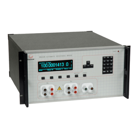
GuildlineInstruments6622ASeriesDCC ResistanceBridge
GuildlineInstruments6675or 6675A SeriesDCCResistanceBridge
GuildlineInstrumentsModel 9975A
(b) LaboratoryGradePrimaryResistanceStandard(AcceptableModels)
GuildlineInstruments6634A-X TemperatureStabilizedResistanceStandards
GuildlineInstruments 9334A SeriesAirResistance Standards
GuildlineInstruments9330SeriesOilResistanceStandards
(c) LowThermalLead Setsor Low Thermal Wire (AcceptableModels)(for Rs)andAppropriatelyrated
leadsforCurrentLeads(150mAto300A)
Guildine6622A: PrecisionLeadSetForResistanceBridge
SCW-30:18AWG:18GuageLowThermalWire
92303LeadSet(300A,1.5 m)
92321LeadSet(150 A,1.5m)
92301LeadSet(20A,1.5m)

Section 4
TM9711B-A-00
6 November 2013
4-3
4.5 Routine Calibration
This routine calibration procedure describes the calibration currents required for the 9711B Multi-
Tap Current Shunt. The procedure is intended to be used as a reference for qualified metrology
personnel who have a primary level standards laboratory with equipment available to support an
instrument of thislevel of standards accuracy.
Qualified personnel means that the technician or metrologist performing the calibration has the
necessary level and understanding on Direct Current Comparator Resistance Measurements and
errors from sources such as guard errors, thermal emfs, temperature and or EMI errors and others.
The procedure assumes operators will make adequate allowance for equipment stabilization and
measurementsettling times.
For the best uncertainties with least operational influence on the measurements, it is
recommended that customers use automation technologies such as Bridgeworks-R or
Bridgeworks-C Software, IEEE control and 6664X Series Low Thermal Scanners (can be used for
automation ofmeasurements up to 2 A).
Calibration Notes
Always check availability of equipment and standards prior to starting the calibration If the required
equipmentisnotavailable,donotproceedwiththecalibration.
Ensureallequipmentusediswithinthecalibrationvalidityinterval.
Before beginning the calibration, inspect the UUT for damage and cleanliness. If the UUT is not in
suitablecondition forcalibration,pleasecleanorrepairbefore proceeding.
Leads can have an impact on overall measurements. Ensure that the leads selected are Metrology
Grade leads. While 300 A leads are called out for the 300 A range, Guildline uses 500 A leads for this
measurement to avoid temperature affects on measurements. Your measurement may or may not
beaffecteddependingonthequalityoftheleads.

Section 4
TM9711B-A-00
6 November 2013
4-4
Table4-1: Listof RecommendedTestCurrentsorVoltagesForResistanceValues
Ampere
Input
Range
Resistance
Recommended
Test Currents
Foot
Notes
Comments
300
0.333 333 m
30 Adc
100 Adc
300 Adc4
1, 4
6623A-300 Range Extender required .
Calibrate in order (minimum current to maximum
current)
100
10 Adc
100 Adc
1,2
6623A Range Extender required
Calibrate in order (minimum current to maximum
current)
10
1.0 Adc
10 Adc
1
6623A Range Extender required
Calibrate in order (minimum current to maximum
current)
1
0.1 Adc
1 Adc
2
6623A Range Extender required
Calibrate in order (minimum current to maximum
current)
0.1
0.01 Adc
0.1 Adc
3
Calibrate in order (minimum current to maximum
current)
0.01
0.001 Adc
0.01 Adc
3
Only 6622A Bridge Required (No Range Extender
needed) for Remaining Tests. Calibrate in order
(minimum current to maximumcurrent)
0.001
0.000 1 Adc
0.001 Adc
3
Only 6622A Bridge Required (No Range Extender
needed) for Remaining Tests. Calibrate in order
(minimum current to maximum current)
0.000 1
0.000 1 Adc
3
Only 6622A Bridge Required (No Range Extender
needed) for Remaining Tests.
0.000 01
0.000 1 Adc
3
Only 6622A Bridge Required (No Range Extender
needed) for Remaining Tests.
1 Requires 6623A Series Range Extender
2 Requires either 6623A Series Range Extender or 6623A-2 (With Built in Supply)
3 Can use any of the recommended Bridges
4 OptionalCalibrationPointscanbeusedin placeofStandardPointoraddedtostandardpointsforcalibraiton.

Section 4
TM9711B-A-00
6 November 2013
4-5
4.6 Nominal Value Calibration Procedure
4.6.1 RecordtheUUTInformationonTable4.
(b) Allow the 9711B to stabilize at Calibration environment for a 24 hour period. Ensure that the
roomisproperlyventilatedtodissipateheatupto30Wofpowerforthecalibrationprocess.
(c) Setup DCC Bridge and Range Extender and other standards used for appropriate measurement
(refertoStandardsManualsused).
4.6.2 Calibrationof 0.01 mA (10 k ) Ranges to 1 A (0.1 Ranges)
(a) Connectthethe6622ASeriesBridgedirectly(C1andC2)totheCommonandPotentialterminals
onthe9711B.
Note: Thecableswillremainconnectedin thisconfigurationfortheremainderofthe calibration.
(b) MovethetwoRangePlugsto0.01 mA. AllowtheUUTtostablize10minutespriortostartingthe
measurements
(c) Output the first current (starting with lowest current) for the 0.01 mA range and after proper
bridge measurement cycle (refer to user manuals for bridge, record the UUT value under
MEASURED VALUE ontheworksheet.
(d) Unitvalueshould bebetweentheminimumand maximumvalues. Ifnot,unitwill requirerepair.
(e) Repeat for all currents listed for each test point. Always start with lowest current (minimum heat
dissipation) andworkto highestcurrent.
(f) RepeatStepsbthroughdforremainingvalues.
4.6.3 Calibration of 1 A (100 m ) Range
(a) Disconnect the current (C1 and C2) lead sets and connect a cable
capable of handling 1 A ut Common
Terminals. Connect the other end to the 6623A Range Extenders 2 A
Input Common cable connection to the high and low terminals.
Potential Cablesshould remain connectedasbefore.
(b) MovethetwoRangePlugsto1A. AllowtheUUTtostablize10minutes
priorto startingthemeasurements
(c) Output the first current (starting with lowest current) for the 1 A and after proper bridge
measurement cycle (refer to user manuals for bridge), ), record the UUT value under MEASURED
VALUEontheworksheet.
(d) Unitvalueshould bebetweenthe minimumandmaximumvalues. Ifnot, unitwill requirerepair.

Section 4
TM9711B-A-00
6 November 2013
4-6
(e) Repeat for all currents listed for each test point. Always start with lowest current (minimum heat
dissipation) andworkto highestcurrent.
4.6.4 Calibration of 10 A (10 m ) Range
(a) Disconnect the 1 A Current Cables Cable and connect a cable capable of handling 10 A to the
10 A and Input Common Terminals. On the 6623A Range Extender, move the Input
Common cable connection to the appropriate range extender 15 A output high and low.
Potential Cablesshould remain connectedasbefore.
(b) Move the two Range Plugs to 10 A. Allow the UUT to stablize 10 minutes prior to starting the
measurements
(c) Output the first current (starting with lowest current) for the 10 A and after proper bridge
measurement cycle (refer to user manuals for bridge), record the UUT value under MEASURED
VALUEontheworksheet.
(d) Unitvalueshould bebetweentheminimumand maximumvalues. Ifnot,unitwill requirerepair.
(e) Repeat for all currents listed for each test point. Always start with lowest current (minimum heat
dissipation) andworkto highestcurrent.
4.6.5 Calibration of 100A (1 m ) Range
(a) Common and Potential Cables should remain connected as
before. Disconnect the 10 A Current Cables and connect a cable
capableofhandling 300 A to the 100 A and Input Common
(Right side) and to the 6623A-300 Range Extender 300 A output.
Potential Cablesshould remain connectedasbefore.
(b) Move the two Range Plugs to 100 A. Allow the UUT to stablize 10
minutespriortostartingthemeasurements
(c) Output the first current (starting with lowest current) for the 100 A and after proper bridge
measurement cycle (refer to user manuals for bridge), record the UUT value under MEASURED
VALUEontheworksheet.
(d) Unitvalueshould bebetweentheminimumand maximumvalues. Ifnot,unitwill requirerepair.
(e) Repeat for all currents listed for each test point. Always start with lowest current (minimum heat
dissiapation)andworktohighestcurrent.
4.6.6 Calibration of 300 A (0.333 333m ) Range
(a) Connect leads capable ofhandling300 A to the 9711BInputCommon (Rightside)and the 300A
Terminalstothe6623A-300RangeExtenderoutputhighandlow.
Table of contents
Other Guildline Measuring Instrument manuals

Guildline
Guildline 9211B Series User manual

Guildline
Guildline 9334A Series User manual

Guildline
Guildline 6622T Series User manual

Guildline
Guildline 6675A User manual

Guildline
Guildline 6634A Resistance Standard User manual

Guildline
Guildline 7520 Guide

Guildline
Guildline 6622A Series User manual

Guildline
Guildline 6530 Series User manual
Popular Measuring Instrument manuals by other brands

Panasonic
Panasonic KW2M installation instructions

Agilent Technologies
Agilent Technologies N4373A user guide

BIONIME
BIONIME Rightest GM700 Getting started guide

MetroPWR
MetroPWR FX700 user manual

Konica Minolta
Konica Minolta CA-210 brochure

PCB Piezotronics
PCB Piezotronics IMI SENSORS ICP M628F01 Installation and operating manual