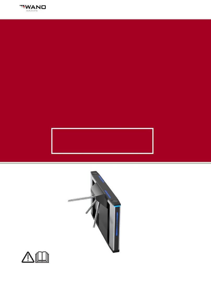
Gunnebo DL645 User manual

M00000118-E-uk – 06.07 DL645 and Simplex 45
Operation and Maintenance Manual
DL645
Simplex 45

M00000118-E-uk – 06.07 DL645 and Simplex 45
Document history
Rev. Date Aut. Description Page Section
A 27/10/2004 CT First issue
B 10/12/2004 CT
C 28/01/2005 CT
D 30/03/2007 VM Simplex 45 ATT added; full document
review
E 06/06/2007 VM Simplex 45 ATT schematics reviewed

2
M00000118- E-uk – 06.07 DL645 and Simplex 45
Contents
SECTION 1 Introduction Page
General.................................................................................................5
Electrical Warnings...............................................................................5
Errors....................................................................................................5
Proprietary Notices...............................................................................5
Hardware Changes...............................................................................5
General Condition of Use.....................................................................6
Rotating Machinery...............................................................................6
Warnings, Cautions and Notes.............................................................6
Static Sensitive Devices.......................................................................6
Good Practices.....................................................................................6
Equipment Safety Systems ..................................................................7
Risk Assessment..................................................................................7
CE - Marking.........................................................................................8
Important Notice...................................................................................8
SECTION 2 Product Description
General Details.....................................................................................9
Technical Details................................................................................12
Technical Specification.......................................................................12
SECTION 3 Instruction for Use
Important Notices ...............................................................................14
Signs and Symbols.............................................................................14
Operating Modes................................................................................15
Normally Closed Transit Sequence....................................................15
Normally Open Transit Sequence......................................................16
Emergency / Fire Alarm......................................................................16
Traffic Lights and Pictograms.............................................................16
Alarms.................................................................................................17
Remote Control interface ...................................................................17
RS485 Serial Line...............................................................................17
Programmable Parameters and Trimmers.........................................18
Reader Authorization Signal Management ........................................18
Counting pulse and other output signals............................................19
SECTION 4 Technical Information
Components Location.........................................................................20
Hercules Mechanism Construction ....................................................21
Die Cast Base.....................................................................................21
Rotary Unit..........................................................................................21
Locking Device...................................................................................22
Positioning Device..............................................................................23
Damper...............................................................................................23

3
M00000118- E-uk – 06.07 DL645 and Simplex 45
Anti Reversal Device..........................................................................23
Positioning Sensors............................................................................23
Sensor Actuators................................................................................23
Sensors...............................................................................................24
Tripod..................................................................................................24
Static Hub Version..............................................................................24
Emergency Drop Arm Device (Optional)............................................25
Electrical Schematics .........................................................................26
LL2001 Control Logic Board...............................................................29
LL2001 Board Inputs..........................................................................30
LL2001 Board Outputs .......................................................................31
LL2001 Board Connectors .................................................................32
Power supply unit...............................................................................34
SECTION 5 Installation
Unpacking...........................................................................................35
Tools required.....................................................................................35
Site Preparation..................................................................................35
Environmental conditions ...................................................................35
Power Supply Characteristics ............................................................36
General Conditions.............................................................................36
Cabling................................................................................................37
Mounting Details.................................................................................38
Unit Positioning...................................................................................41
Electrical Connections........................................................................42
Power Supply .....................................................................................42
Connection with readers.....................................................................43
MP2000 Remote Control Unit connection..........................................43
Emergency / Fire Alarm......................................................................44
RS485 Serial Line...............................................................................44
SECTION 6 Maintenance
General Care......................................................................................45
Routine Maintenance..........................................................................46
Monthly Checks..................................................................................46
Annual Checks ...................................................................................46
Trouble-Shooting................................................................................48
Fault Finding.......................................................................................49
LL2001 Board Replacement...............................................................50
SECTION 7 Spare Parts........................................................................................51
SECTION 8 Table Appendices
Table 8.1 Trimmer TR1 (Solenoids configuration).............................54
Table 8.2 Trimmer TR2 (Reader management).................................54
Table 8.3 Trimmer TR3 (Timings)......................................................55
Table 8.4 Trimmer TR4 (Authorizations stacking,
Counting pulse sequence)..................................................................55
Table 8.5 Trimmer TR5 (REL2, REL3, Traffic Lights)........................56


4
M00000118- E-uk – 06.07 DL645 and Simplex 45
Table 8.6 Trimmer TR6 (IN-AUX, OUT-AUX)....................................57
Table 8.7 Trimmer TR7 (Mode A and B, Remote
Controls).............................................................................................58
Table 8.8 Trimmer TR8 (REL1)..........................................................58
Table 8.9 LL2001 dip-switches configuration for RS485
serial line address assignment...........................................................59
SECTION 9 Declaration of Conformity ...............................................................60

5
M00000118- E-uk – 06.07 DL645 and Simplex 45
Section 1
Introduction
General
Please read this manual carefully, it contains information that will assist you with all aspects of
installation and maintenance, including unpacking, so that a long and useful machine life can be
achieved.
Gunnebo Entrance Control makes every effort to ensure that this manual is reviewed whenever
significant changes are made to the design. However, our policy of continuous improvement
may result in some small differences between the unit supplied and the description in this
document.
Enquiries in this respect should, in the first instance, be directed to our Technical Support
Department.
Telephone +44 (0) 1825 746105.
Electrical Warnings
The electrical power used in this equipment is at a voltage high enough to endanger life. Before
carrying out maintenance or repair, you must ensure that the equipment is isolated from the
electrical supply and tests made to verify that the isolation is complete.
When the supply cannot be disconnected, functional testing, maintenance and repair of the
electrical units is to be undertaken only by people fully aware of the danger involved and who
has taken adequate precautions and training.
Errors
Reports on errors, comments and suggestions concerning this manual are requested and
encouraged. They should be submitted to:
Gunnebo Entrance Control - Technical Support Department
Telephone +44 (0) 1825 746105.
Proprietary Notices
All data appearing herein is of a proprietary nature, with exclusive title to it held by Gunnebo
Entrance Control. The possession of this Manual and the use of the information is therefore
restricted only to those persons duly authorized by Gunnebo Entrance Control.
Do not reproduce, transcribe, store in a retrieval system or translate into any human or
computer language, any part of this Manual without prior permission of Gunnebo Entrance
Control.
Hardware Changes
No hardware changes may be made without authority from Gunnebo Entrance Control, who will
be responsible for ensuring that the proposed change is acceptable in all safety aspects. Only
personnel authorized by Gunnebo Entrance Control may make hardware changes.
Any maintenance or modification of Emergency Stop and Guarding Circuitry must be followed
by safety checks on the whole hardwired Emergency Stop and Guarding Circuitry.
Prior to a hardware change, records must be made of the change, one of which MUST be sent
to the Gunnebo Entrance Control Technical Department.

6
M00000118- E-uk – 06.07 DL645 and Simplex 45
General Condition of Use
This equipment could not be used in potentially explosive atmospheres.
This equipment could not be installed along escape routes or obstructing emergency exits.
Rotating Machinery
Rotating industrial machinery may possess huge amounts of stored energy. On no account
should maintenance be started unless all aspects of safety precautions normally associated
with industrial electronic control systems and machines are fully understood.
Before starting to work on the equipment, ensure that all personnel are familiar with the
associated blocks in the system, including control loops, mechanics, drives, transducers and
electrics. Please read all the Equipment Manuals first.
Warnings, Cautions and Notes
Where necessary within the technical manual, Warnings, Cautions and Notes may be given.
Warnings
Are for conditions that might endanger people. The instructions given in Warnings must be
followed precisely. They are given to avoid injury or death.
Cautions
Are for conditions that may cause damage to equipment, or may spoil work. The instructions
given in Cautions must be followed to avoid spoilt work or damage to equipment.
Notes
Alert the user to pertinent facts and conditions.
Static Sensitive Devices
Some of the PCB’s in the equipment covered by this Technical Manual contain Static Sensitive
Devices. It is recommended that maintenance and service engineers are fully aware of the
Local Industry Regulations and procedures when handling such devices.
Good Practices
Equipment being installed must not be left unattended unless all potential mechanical and electrical
hazards have been made safe. A competent person must be left in charge when the equipment is in a
potentially unsafe condition.
The following points indicate good practice that will contribute to safety and avoid equipment
damage.
i Ensure that all electrical power supplies and batteries are turned OFF and
disconnected before working on any of the equipment.
ii Never leave the equipment in a potentially dangerous state.
iii Use only the correct tools for the task in hand.
iv When working on the equipment, remove any personal jewellery that may be
conductive, or clothing that may become entangled with mechanical parts.

7
M00000118- E-uk – 06.07 DL645 and Simplex 45
Equipment Safety Systems
Safety systems and controls, such as interlocks, covers and guards, must not be overridden or
bypassed by personnel other than authorized staff who are qualified to carry out prescribed
actions within specified Warnings.
Risk Assessment
Risk assessment is graded into categories of safety, rated 1 to 8 (where 8 is the highest risk
level). The following activities are covered.
Rating Activity
1 Cleaning
2 General Installation
3 Servicing
4 Servicing
General Maintenance
Using Chemical Fixers
5 Commissioning
8 Floor Drilling
Rating 1: Cleaning.
Who is at Risk Engineers or Site Personnel
Hazard Mis-use of Cleaning Fluids
Current Controls Compliance with health regulations
Rating 2: General Installation
Who is at Risk Site Personnel
Hazard Objects/Tools in Installation area
Current Controls Trained Installation Engineers
Rating 4: General Maintenance
Who is at Risk Site Personnel
Hazard Electric Shock
Current Controls Isolation of Power/Trained Service Personnel
Using Chemical Fixer
Who is at Risk Site Personnel within the Vicinity of the Work Area
Hazard Fume Inhalation
Current Controls Compliance with health regulations
Rating 5: Commissioning
Who is at Risk Site Engineer
Hazard Power Supply/Moving Parts
Current Controls Isolate Power

8
M00000118- E-uk – 06.07 DL645 and Simplex 45
Rating 8: Floor Drilling
Who is at Risk Installation Engineer
Hazard Flying Debris and Noise
Current Controls Protective Equipment must be worn
CE - Marking
The Gunnebo Entrance Control Spa Hercules-Lite Tripod are CE marked, developed and
manufactured according to the EU’s Low-Voltage and EMC-Directives.
Important Notice
The Gunnebo Entrance Control Hercules-Lite Tripods is a security product, any children or
minors using the turnstile must be supervised and accompanied by a responsible adult.
Gunnebo Entrance Control does not accept any liability if this rule is not enforced.

9
M00000118- E-uk – 06.07 DL645 and Simplex 45
Section 2
Product Description
The Gunnebo Entrance Control Hercules-Lite Tripod range is designed for applications where
an high flow rate is required maintaining a high degree of security.
General Details
Figure 2.1 DL645 turnstile

10
M00000118- E-uk – 06.07 DL645 and Simplex 45
Figure 2.2 Simplex 45 turnstile

11
M00000118- E-uk – 06.07 DL645 and Simplex 45
Figure 2.3 Simplex 45 ATT turnstile

12
M00000118- E-uk – 06.07 DL645 and Simplex 45
Technical Details
The Hercules-Lite turnstile consists of stainless steel cabinet which dimensions and shape
depend on the model.
The cabinet contains and supports the mechanism that controls the rotation of a Head
Assembly that has three tubular arms. These arms are positioned at 120°intervals so that when
the unit is at rest one arm will always be in the horizontal position – BARRIER POSITION.
The movement of the head assembly is controlled by two solenoid devices, which allow rotation
in both directions.
The passageway can be controlled by devices such as card readers, or local and remote push
buttons.
The head assembly is moved manually by the person using the turnstile.
Technical Specification
Orientation: Pass Left or Pass Right
Drive: Hand Operated
Material: Stainless steel AISI 304 Scotch-BriteTM finished
Casework Lid Standard stainless steel AISI 304 Scotch-BriteTM
finished
Hercules-Lite Tripod Hub: Cast Aluminium with grey finish.
Hercules-Lite Tripod Arms: 38mm diameter 480mm AISI 304 polished stainless
Steel with welded end caps.
Function: Passage in both directions, electronically controlled.
Mechanism: Control of the Hercules-Lite Tripod operation is
achieved by an electro- mechanical head mechanism
located within the top section of the turnstile casework.
The unit has the following features as standard:
Normally Closed – The mechanism is locked until a
valid authorisation signal is received.
Normally Open – The mechanism is permanently
unlocked and will only lock if passage is attempted
without a valid authorised signal.
In this mode the MTBF is increased from 1.5 to 2.5
million cycles and increases passage through-put
speed.
Power Supply: 115/230 Vac 50/60Hz

13
M00000118- E-uk – 06.07 DL645 and Simplex 45
Power Rating: Depend on the mechanism configuration:
Fail-Safe in N/C mode: 39W Stand by or Alarm
30W Passage
Fail-Safe in N/O mode: 10W Standby or Passage
39W in Alarm condition
Fail-Lock in N/C mode: 10W Stand by or Alarm
20W Passage
If equipped of optional Drop Arm device:
Fail-Safe in N/C mode: 50W
Fail-Safe in N/O mode: 20W Standby or Passage
50W in Alarm condition
Fail-Lock in N/C mode: 20W
Logic Voltage: 24Vdc
Power Failure: In the event of an emergency or isolation of the power
supply the Hercules-Lite Tripod can be configured to
Fail-Safe i.e. rotates freely or Fail-Lock i.e. locks in the
HOME position.
Either option is available in both or one direction.
Fire Alarm: Input facility available for free voltage contact (normally
closed) supplied by others to effect fail state.
Interface: The mechanism is controlled by means of a
Microprocessor control logic with the following features:
•Three Built-In sensors detecting the mechanism
position
•One input for opening the mechanism in each
direction.
•Four protected outputs (refer to LEDs / Way mode
indicators in Section 4) for piloting light mode
indicators (2 symbols)
•Two protected outputs available for counting
passage in either direction.
•Two dry contacts (0V) output relays available for
indicating availability of use in either direction or
availability for counting passage in either direction.
•Two open collector NPN outputs (refer to EXIT
Characteristics in Section 4) available for indicating
use in either direction or availability for counting
passage in either direction or activate alarms
and/or the ‘Drop Arm’ features.
•One serial port – RS485
Operating Temperature: 0 to 45°C
Transportation and Storage: -25 to +55°C
Relative Humidity: 95% Non condensing.

14
M00000118- E-uk – 06.07 DL645 and Simplex 45
Section 3
Instruction for Use
The information contained in this section should be used as a base for the instruction of
personnel in the correct use of the Hercules-Lite Tripod Range of Barriers.
The Hercules-Lite Tripod turnstile is unlocked by presenting a personalised identity card or
device to the access control reader. (Supplied by others) It can also be unlocked by activating
a casework or remote reception push button, if fitted. This will release the mechanism locking
solenoids and render the Hercules-Lite Tripod ready for use by walking through the walkway
passage in the desired direction.
Should the user decide not to proceed with the passage, the locking solenoid will remain
unlocked for a predetermined time after which it will ‘time out’ and reset the unit making it
available for the next person.
Important Notices
•DO NOT try to push the rotor by hand as you walk through the barrier
•DO NOT walk through the barrier with large bags or briefcases in front or trailing
behind you.
•DO NOT drag bags over the top casework. (Always lift bags over the top of the
barrier).
Should any item become caught in the rotor, STOP, and DO NOT keep forcing through in the
same direction.
Signs and Symbols
In this manual the conventional signs shown in the Figure 3.1 will be employed. Direction A is
the direction where the mechanism (or the rotor’s cabinet) is to the right when passing through
the turnstile.
Figure 3.1 Schematic Diagram of the Unit.
Head
Assembly
Direction A Direction B
Solenoid A Solenoid B

15
M00000118- E-uk – 06.07 DL645 and Simplex 45
Operating Modes
The Hercules-Lite Tripod turnstile is bi-directional. The two directions can be separately
configured as follows:
•Unlock mode: passage is authorised for all users in the desired direction;
•Lock mode: passage is inhibited in the desired direction;
•Reader control mode: the passage is possible only for those users who are recognised
by the badge reader.
The mode for each direction can be set by means of:
•setting of the control logic trimmers position (see Section 8 - table 8.7);
•remote control (optional Gunnebo Entrance Control MP2000 control module);
•RS485 serial interface (through the Gunnebo Entrance Control proprietary serial
protocol).
The action of the Remote Control or the Serial Control has priority over the trimmers position
setting.
The HERCULES locking device can be supplied in two versions that can be factory or site set:
•(FL) Fail Locked – mechanism locked in the absence of the power supply;
•(FS) Fail Safe – mechanism released in the absence of the power supply.
In consequence of this mechanical setting, a trimmer of the LL2001 electronic board must be
adjusted as described in Section 8, table 8.1.
Within these versions the control logic offers two operating modes:
Normally Closed - Controlled Transit in Standard Mode (STD)
At rest the rotary unit is locked. On receipt of an authorisation signal from the reader unit, the
solenoid releases rotation in the required direction.
Normally Open – Controlled Transit in Permanently Open Mode (SA)
At rest the rotary unit is unlocked and free to rotate in both directions. An attempt to turn the arm
without the due authorisation will activate the solenoid and block rotation.
Note - The solenoids can be configured for both FL and FS operation.
The required operating mode can be selected by setting the appropriate Trimmer position.
Normally Closed Transit Sequence
At rest, rotation is prohibited in both directions and solenoids ‘A’ and ‘B’ will be de-energised in
the FL configuration (energised in FS mode).

16
M00000118- E-uk – 06.07 DL645 and Simplex 45
If the authorisation signal enabling transit in direction ‘A’ is received from the reader unit,
rotation will be released in that direction (‘A’ energised in FL – de-energised in FS)
To lock the Hercules-Lite Tripod on completion of rotation, the locking arm is recalled (‘A’ de-
energised in FL or energised in FS) when the Hercules-Lite Tripod has rotated approximately
67Ofrom the starting point.
During the entire rotation solenoid ‘B’ remains de-energised in FL configuration (energised in
FS) in order to perform the anti-reversal function.
The system operates in the same manner for transit in direction ‘B’.
Normally Open Transit Sequence
At rest, rotation is not prevented by the solenoids that are energised in the FL configuration (de-
energised in FS)
If a person attempts to rotate the Hercules-Lite Tripod in direction ‘A’ without authorisation
having been received from the reader unit – solenoid A will lock the Hercules-Lite Tripod after it
has rotated approximately 10O. Only when the Hercules-Lite Tripod has returned to the
BARRIER position will the rocker arm release.
Note - The same action applies for direction ‘B’.
During transit in any direction, if an attempt is made to reverse the Hercules-Lite Tripod the anti-
reversal device will only intervene if the Hercules-Lite Tripod has already completed a rotation
of 670 in the authorised direction.
The anti-reversal device operates when the control logic detects a rotation of approximately
3.3O in the opposite direction to that authorised. Solenoid ‘B’ will operate if the authorised
direction is ‘A’ or vice-versa. The solenoid releases the rocker arm only when the Hercules-Lite
Tripod is rotated a further 6.6Oin the authorised direction.
Emergency / Fire Alarm
The Hercules-Lite turnstile offers an input (normally closed) in order to receive an Emergency /
Fire Alarm remote command (by other).
When this command is active, the control logic releases the rotation of the tripod in both
directions. This condition will remain for the duration of the signal being received by the control
logic.
If the turnstile is equipped of optional drop arm device, when the command is active, the arm in
the barrier position is released in order to leave the passageway open.
Connection details are given in Section 5 of this manual.
Traffic Lights and Pictograms
In order to facilitate the transit flow, optional traffic lights and pictograms are available which
show when a turnstile is programmed with the lock mode or is already engaged in the other
direction (red cross). Similarly the presence of a green arrow indicates that a user can pass
through the turnstile. In case of pictogram, an additional card reader sign indicates that the
entrance is ready to accept the access control system authorization.
If this optional are used, a trimmer of the LL2001 electronic board must be properly configured
(see Section 8 – table 8.5).

17
M00000118- E-uk – 06.07 DL645 and Simplex 45
Alarms
If a person attempts to rotate the Hercules-Lite Tripod without authorisation having been
received from the reader unit the control logic will interpret this as an attempt at fraud (‘Fraud’
alarm). In the SA mode the solenoid locks rotation.
The rocker arm is released when the Hercules-Lite Tripod returns to the BARRIER position.
In every case, the tripod rotation must be completed within 8 seconds from the leaving of the
BARRIER position, otherwise the control logic will signal an alarm (‘Positioning’ alarm). The
alarm is reset when the Hercules-Lite Tripod returns to the BARRIER position.
If the Hercules-Lite is equipped of Drop Arm device, the control logic detects if the arm in barrier
position is dropped. In that case, the control logic will signal an alarm (‘Drop Arm’ alarm). The
alarm is reset when the arm is restored in the barrier position.
The Simplex 45 ATT model is equipped of two photocells and/or a sensitized top lid in order to
recognise the attempts of cross the barrier without authorization. If these sensors are activated
when the control logic is not processing any authorized rotation, an alarm will be triggered. That
alarm is reset 3 seconds after the sensors de-activation.
The photocells alarm is automatically inhibited when the Unlock operating mode is set for, at
least, one direction. In that case, only the sensitized top lid alarm is active.
During all the described alarm conditions, the control logic locks the rotating head and signals
that status by means of the buzzer activation, the flashing red cross on the traffic lights and
activating a dry contact output.
By means of a trimmer (see Section 8 – table 8.8). it is possible to choice which alarm has to be
signalled by the dry contact output.
Remote Control interface
The Hercules-Lite turnstile control logic offers an electrical interface in order to allow the remote
control of entrance.
By means of the optional Gunnebo Entrance Control MP2000 control module, the operation
modes of the unit can be set by a remote consol (see connection details is Section 5 of this
manual).
In case the remote control is needed, a trimmer of the LL2001 must be set as described in
Section 8 – table 8.7.
RS485 Serial Line
The Hercules-Lite turnstile control logic can be interfaced with RS485 serial line using the
Gunnebo Entrance Control proprietary protocol. In this way the operating modes, alarms and
transit information are available for full integration with the access control system.
In case the serial line connection is used, a trimmer of the LL2001 must be set as described in
Section 8 – table 8.7.
If more than one Hercules-Lite turnstile unit must be connected to the same bus, it is possible to
assign an address to each one by means of the dip-switches mounted on the LL2001 electronic
board. Up to 16 units can be addressed into the bus (see section 8 - table 8.9 for addresses
assignment).
The description of the proprietary protocol can be required to the Technical Support; connection
details are available in Section 5 of this manual.
In order to improve the interfacing capability of the serial line, it is possible to slow down the
transmission flow from the Hercules-Lite turnstile’s serial port by means of a trimmer mounted
on the LL2001 electronic board (see section 8 – table 8.3).

18
M00000118- E-uk – 06.07 DL645 and Simplex 45
Programmable Parameters and Trimmers
The Hercules-Lite turnstile operational modes are affected by the positions of the eight trimmers
mounted on the LL2001 board; their functionality is resumed in Section 8 of this manual.
When the control logic microprocessor executes the resident program it consults the current
position of the trimmers in order to set the timings of certain actions and internal algorithms.
Note
•When ONE or MORE trimmer position is changed, it will be necessary to press
the RESET Button on the LL2001 Board.
•Modifications to the trimmers setting should only be carried out by trained
personnel.
•When the trimmers setting is changed, it is important to record the new and the
old configuration.
Reader Authorization Signal Management
In the Reader-Controlled Mode, the logic system waits for the card reader to send an unlock
signal that authorizes passage.
The signal sent by the reader can be interpreted in three ways.
•Unlock on Front: the logic identifies as authorisation the transition from non active to
active (of the unlock signal). In this moment the logic starts to count down the transit
time out;
•Unlock on Level: the logic identifies as authorisation the transition from active to non
active (of the unlock signal). In this moment the logic starts to count down the transit
time out;
•Copy: the logic keeps the system unlocked for a period corresponding to when the
reader signal is sent.
Operate the choice by means of a trimmer mounted on the LL2001 electronic board (see
section 8 – table 8.2).
The “Unlock on Front” mode is set by default from factory. In this modality, the logic records
authorisation signals that arrive while the door is still being used.
The maximum number of authorisation signals that can be recorded is determined by the TR4
trimmer position.
See also section 5 for connection details.

19
M00000118- E-uk – 06.07 DL645 and Simplex 45
Counting pulse and other output signals
The electrical outputs of the LL2001 control board are available to interface the Hercules-Lite
turnstile to the ticket readers and the surrounding systems.
To obtain the most flexible signals interface, a logic function attributed to each one of these
outputs can be set with by means of the LL2001 trimmers setting.
The available outputs are listed below (electrical details in Section 4):
id description connector / pin assignment
trimmer
REL1 dry contact relay USER-INT pin 6, 7 TR8
REL2 dry contact relay (NC/NO) OUT-CRD pin 1, 2 TR5
REL3 dry contact relay (NC/NO) OUT-CRD pin 3, 4 TR5
auxiliary output 1 npn open collector OUT-AUX pin 2 TR6
auxiliary output 2 npn open collector OUT-AUX pin 3 TR6
LIGHT-A pin 4 npn open collector (*) LIGHT-A pin 4 TR5
LIGHT-B pin 4 npn open collector (*) LIGHT-B pin 4 TR5
(*) available when pictograms are not used.
The available logic functions are listed below:
‘counting pulse’: It acknowledges the occurred transit in one direction. An
output is available for each passage direction.
The pulse is generated every time the rotor reaches an half
or full rotation angle (the choice is made by the TR4
trimmer).
The duration of the counting pulse can be chosen between
two values by means of the TR3 trimmer.
‘enable reader’: It signals when the logic is ready to accept authorizations
from the card reader in one direction. An output is available
for each passage direction. If the entrance is not configured
in the Reader-Controlled Mode or is in some alarm
condition, the ‘enable reader’ signal is off.
‘presence of power’: It signals that the gate is powered on.
‘alarms’: It signals an alarm condition with the permanent activation
of the output.
‘buzzer’ It signals an alarm condition with the intermittent activation
of the output
This manual suits for next models
1
Table of contents
Other Gunnebo Turnstile manuals
Popular Turnstile manuals by other brands

Magnetic Autocontrol
Magnetic Autocontrol MPT-333 operating instructions

Ravel
Ravel RMC-PRS-56E-PUN Operation manual

Alvarado
Alvarado Supervisor 2000 installation instructions

Turnstiles
Turnstiles MPW 112 operation instruction

Aventura
Aventura TS-TTS01 installation manual

Automatic Systems
Automatic Systems TriLane TL1 quick start guide