GWS TIGARC 200 AC/DC Operating and maintenance manual

INSTRUCTIONAL MANUAL

1
Contents
Features
1.0 Recommended Safety Precautions ........................ 2
1.1 Health Hazard Information.................................... 2
1.2 Personal Protection ................................................ 2
1.3 Electric Shock .......................................................... 3
1.4 User Responsibilities .............................................. 3
• AC/DC TIG, MMA
• Single phase input from 230V±10%
• Microprocessor, precise control.
• Anti-sticking, Arc force, Hot start
• Electric HF ignition: Easy arc striking
• Remote control (Optional Feature w/ Torch)
• Foot pedal ready
• AC balance: high quality welds on Aluminum
• Higher AC frequency (50-250Hz), fast travel speed
• Smart-V technology: Better ignition, lower loss
• Soft Switching: low consumption, small but stable
• Intelligent protection: Over-voltage, Low-voltage,
Over-current and Over-heat
• PFC technology (Power Factor Correction)
• TIG Pulse function and all Pulse parameters can be
adjusted
• Complies with EN 60974-1
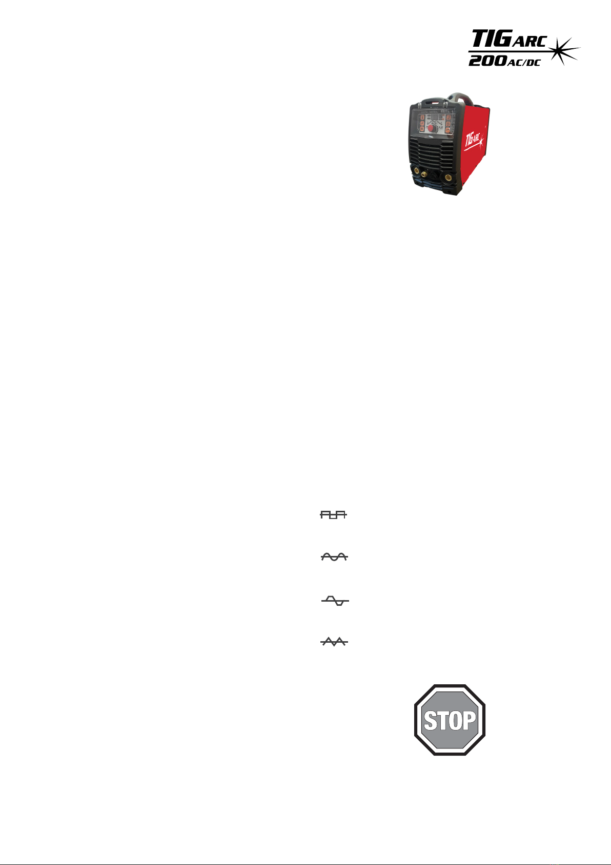
AC Waveforms
Advanced Square wave
Fast freezing puddle, deep penetration and fast
travel speeds
Soft Square wave
For a soft buttery arc with maximum puddle control
and good wetting action
Sine Wave
For those who prefer traditional arc characteristics.
Quieter welding with good wetting
Triangle Wave
Reduces heat input which is ideal for thin
aluminium welding. Allows for faster travel speeds
2.0 Gas Tungsten Arc Welding (GTAW/TIG) ................ 4
2.1 Introduction ............................................................ 4
2.2 Polarity Variations .................................................. 4
2.3 Shielding Gas Selection .......................................... 6
2.4 Consumable Selection ............................................ 7
2.5 Welding Techniques ............................................... 8
2.6 Torch Movement During Welding ......................... 8
2.7 Torch Positioning ................................................... 8
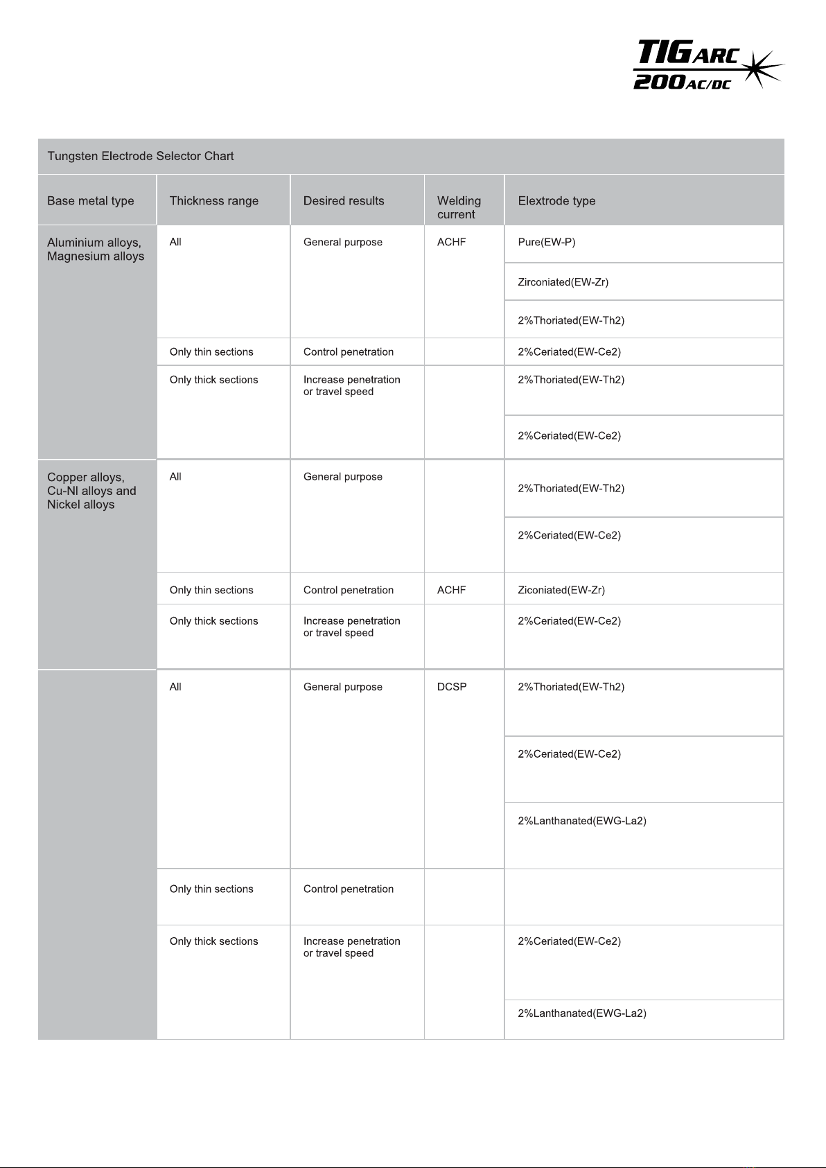
2.8 Non Consumable Tungstens .................................. 9
2.9 Working Principle ................................................. 11
5.0 Troubleshooting.................................................... 25
PLEASE NOTE that under no circumstances should your
TIGARC 200AC/DC be altered or changed in any way from
standard factory configuration. Doing so, will void the
machine warranty.
3.0 Installation and Adjustment ................................ 12
3.1 Parameters.............................................................. 12
3.2 Operation Environment......................................... 12
3.3 Operation Notices .................................................. 12
3.4 Duty Cycle & Over heating .................................... 13
3.5 Polarity Connection (MMA)................................... 13
3.6 Machine layout and components.......................... 14
3.7 Control Panel.......................................................... 15
4.0 Argon Arc Welding Operation ............................. 17
4.1 TIG Welding (4T Operation) ................................. 17
4.2 TIG Welding (2T Operation .................................. 18
4.3 The explanation of welding quality .................... 19
4.4 TIG Parameters...................................................... 19
4.5 Joint Preparation ................................................. 23
6.0 TIG Welding Material Reference ......................... 29
6.1 Application Summary ........................................... 29
6.2 C-Mn Steel ............................................................. 30
6.3 Alloyed Steel ......................................................... 31
6.4 Stainless Steel........................................................ 32
6.5 Aluminium ............................................................ 32
6.6 Balanced Square wave ......................................... 33
6.7 Copper and Copper Alloys ................................... 33
6.8 Direct Current (DC) Tig Welding .......................... 34
6.9 DC Pulse TIG Welding ........................................... 34
8.0 Recommended Safety Guidelines ........................ 36
9.0 Machine Hazards .................................................. 36
7.0 AC TIG Welding ...................................................... 35
10. Warranty Schedule 2021 ...................................... 37

1.1 Health Hazard Information
2
1.0 Recommended Safety Precautions
The welding process can cause a variety of possible hazards
for the operator and those in close proximity. All
appropriate safety precautions should be made to prevent
harm and injury. Although these precautions are not all
inclusive, the following considerations should be followed
for most welding applications. As always, electrical
equipment should be used in accordance with the
manufacturer’s recommendations.
Eyes
The welding process produces ultraviolet rays that can cause
permanent eye damage. In addition, welding fumes may
also cause serious eye irritation.
Skin
Arc rays are dangerous to uncovered skin and will cause
burning of the skin.
Inhalation
Welding fumes and gases are dangerous to both operator
and to those in close proximity. Fumes may cause a number
of respiratory ailments. Excessive exposure may cause
nausea, dizziness, dryness, irritation of nose, throat & lungs
or even permanent lung damage.
1.2 Personal Protection
Respiratory
Welding in confined areas should be carried out with the
aid of a fume respirator or air supplied respirator as per
AS/NZS 1715 and AS/NZS 1716 Standards.
• Ensure proper ventilation at all times
• Keep your head out of the fumes emitted by the arc
• Fumes from the welding of some metals could have an
adverse effect on your health. DO NOT breathe them in.
If you are welding on materials such as stainless steel,
nickel, alloys or galvanised steel, additional
precautions are necessary.
• Wear a respirator when natural or forced ventilation
is not sufficient.
Eye Protection
A welding helmet fitted with the appropriate welding shade
lens for the welding operation must be worn at all times
when welding. The welding arc and the reflecting arc flash
emits ultraviolet and infrared rays. Protective welding
screening and eye protection should be provided for others
working in the area.
Clothing
Suitable clothing must be worn to prevent excessive skin
exposure to UV radiation, sparks and molten metal. Flame-
proof, loose fitting cotton clothing buttoned to the neck,
protective leather gloves, spats, apron and steel toe safety
boots are also highly recommended. In addition, use a
helmet with the recommended shade lens for amperage
listed in the shade chart below.
Ten Points about Cylinder Safety
1) Read labels and Material Safety Data Sheet (MSDS)
before use
2) Store upright and use in well ventilated, secure areas
away from pedestrian or vehicle thoroughfare
3) Guard cylinders against being knocked violently or
being allowed to fall
4) Wear safety shoes, glasses and gloves when handling
and connecting cylinders
5) Always move cylinders securely with an appropriate
trolley. Take care not to turn the valve on when moving
a cylinder
Cylinder Safety
Back view of typical
cylinder valve
Operator wearing personal
protection equipment (PPE) in safe position
Less than 150 amps
150 to 250 amps
250 to 300
300 to 350
Over 350 amps
Use one shade darker for aluminium welding
Shade 9
Shade 10
Shade 11/12
Shade 13
Shade 14

3
When operating the cylinder valve:
• Open by hand turning the valve hand wheel
anti-clockwise using no more than reasonable force
• Ensure that no gas is leaking from the cylinder valve
connection or the system to which the cylinder is
connected. DO NOT use ammonia-based leak detection
fluid as this can damage the valve. Approved leak
detection fluid, can be obtained from your gas provider
• When cylinder is empty, close the valve by turning
the valve hand wheel in a clockwise direction using no
more than reasonable force
Ten Points about Cylinder Safety (continued)
6) Keep in a cool, well ventilated area, away from heat
sources, of ignition and combustible materials,
especially flammable gases
7) Store full and empty cylinders separately
8) Keep ammonia-based leak detection solutions, oil and
grease away from cylinders and valves
9) Never use excessive force when opening or closing valves
10) Don’t repaint or disguise markings or damage.
If damaged, return cylinders immediately
Cylinder Valve Safety
When working with cylinders or operating cylinder valves,
always wear appropriate protective clothing – gloves, boots
and safety glasses. When moving cylinders, ensure that the
valve is not accidentally opened in transit.
Before operating a cylinder valve:
• Ensure that the system you are connecting the cylinder
into is suitable for the gas and pressure involved
• Ensure that hoses are securely connected to the cylinder
valve and system. A hose, for example, can potentially flail
about dangerously if it is not restrained at both ends
and accidentally pressurised
• Stand to the side of the cylinder so that neither you nor
anyone else is in line with the back of the cylinder valve.
This is in case a back-plug is loose or a bursting disc vents.
The correct stance is shown in the “Cylinder Safety”
diagram previously in this section
1.3 Electrical Shock
• Never touch ‘live’ electrical parts
• Earth clamp all work materials
• Never work in wet or damp environments
Avoid electric shock by:
• Wearing dry, insulated boots
• Using dry, leather gloves
• Never changing electrodes with bare hands or wet gloves
• Never cool electrode holders in water
• Work on a dry, insulated floor where possible
• Never hold the electrode or holder under your arm
1.4 User Responsibilities
• Read the Instructional Manual prior to using your
TIGARC 200AC/DC
• Unauthorised repairs to this equipment may endanger
the technician and operator and will void your Warranty.
Only qualified personnel should perform repairs
• Always disconnect mains power before investigating
equipment malfunctions
• Replace broken, damaged, missing or worn parts & hoses
immediately.
• Equipment should be cleaned & serviced periodically

2.0 Gas Tungsten Arc Welding (GTAW/TIG)
4
2.1 Introduction
Either direct or alternating current may be used in the
welding process. For DC operation the tungsten may be
connected to either output terminal, however is most
commonly connected to the negative terminal. The output
characteristics of the power source will have an effect on
both the quality and speed of the weld.
Shielding gas is directed into the arc area through the
welding torch. A collet body inside the torch distributes the
shielding gas evenly over the weld area. In the torch the
welding current is transferred to the tungsten electrode
from the copper conductor.
2.2 Polarity Variations
DCEN
When direct-current electrode-negative (straight polarity)
is used:
• Electrons strike the part being welded at a high speed
• Intense heat on the base metal is produced
• The base metal melts very quickly
• Ions from the inert gas are directed towards the negative
electrode at a relatively slow rate
The increased amperage provides:
• Deeper penetration
• Increased welding speed
• A narrower, deeper, weld bead
• Better arc control
Use of DCEN
For a given diameter of tungsten electrodes, higher
amperage can be used with straight polarity. Straight
polarity is used mainly for welding:
• Carbon steels
• Stainless steels
• Copper alloys
• Titanium
Sheilding gas
Arc
TIG filler rod
Weld pool
Collet body
Tungsten electrode
Workpiece

DCEP
DCEP (reverse polarity) is different from DCEN in the
following ways:
• High heat is produced on the electrode rather than on
the base metal
• The heat melts the tungsten electrode tip
• The base metal remains relatively cool compared to
straight polarity
• Relatively shallow penetration is obtained
Use of DCEP
• Intense heat means a larger diameter of electrode must
be used with DCEP
• Maximum welding amperage should be relatively high
5
High-Frequency AC Welding
Welding with alternating current combines both
direct-current characteristics:
• In the positive phase, cleaning action occurs in
the weld puddle
• During the negative phase, heat is concentrated in
the weld puddle.
• The above causes increased penetration

6
2.3 Shielding Gas Selection
Aluminium alloys
Aluminium bronze
Brass
Cobalt-based alloys
Copper-nickel (Monel)
Deoxised copper
Nickel alloys (Inconel)
Steel
Magnesium alloys
Stainless steel
Titanium

7
2.4 Consumable Selection
Welding Wire
The following table includes the recommended welding consumable for the most commonly welded materials.
0.9 - 1.6
1.6 - 2.0
1.6 - 2.0
2.4
3.2

8
2.5 Welding Techniques
2.6 Torch Movement During Welding
2.7 Positioning Torch Tungsten for Various Weld Joints

9
Non Consumable Tungstens
Mild Steels,
Carbon Steels,
Alloy Steels,
Stainless Steels &
Titanium Alloys
DCEP
DCEN+
100% He
DCEP
DCEN
100% He
DCEN
DCEN
100% He

10

2.9 Working Principle
The working principle of the TIG200AC/DC is shown in the
flowchart below.
The single phase 220V work frequency (50/60 Hz) AC is
rectified into DC (approx 310V) which is then converted to a
medium frequency AC (approx. 44KHz) by using an inverter
device (IGBT module). The voltage is further reduced by
using a medium transformer (the main transformer) and
then rectified by using a medium frequency (fast recovery
diode), then is outputted DC or AC by selecting IGBT
module. The circuit adopts current feedback control
technology to ensure current output stability. The welding
current parameter can also be adjusted continuously to
meet welding requirements.
Single Phase, AC
220V (50HZ) Rectifier
DC
AC or DC
AC or DC
AC
DC
Inverter
Rectifier
Inverter
Hall device
Current
feedback control
AC
11
Transformer
Control
Signal

3 Installation and Adjustment
3.1 Parameters
12
3.2 Operation Environment
• Height above sea level is below 1000m.
• Operation temperature range:-10°C~+40°C.
• Relative humidity is below 90 %(+20°C). relative humidity
is below 50% (40°C).
• The inclination of the power source does not exceed 10°.
• Protect the machine against heavy rain, or in hot
circumstances, against direct sunshine.
• The content of dust, acid, corrosive gas in the surrounding
air or substance can not exceed normal standards.
• Take care that there is sufficient ventilation during
welding. There is at least 30cm free distance between the
machine and wall.
3.3 Operation Notices
• Read section 1 carefully before attempting to use this
equipment.
• Connect the ground wire with the machine directly, and
refer to section 3.
• In the case of closing the power switch, no-load voltage
may be exported. Do not touch the output electrode with
any part of your body.
• Do not watch the arc with no eye protection.
• Ensure good ventilation of the machine to improve duty
ratio.
• Turn off the engine when finished to save power.
• When power switch shuts off protectively because of
failure, don’t restart it until the problem is resolved.
Otherwise, the range of potential problems will be
exacerbated.
TIG MMA
0.5-200
50-250
0.98
0-10
0.1-10/1-10
15-50
square
50/60Hz
45V(Controlled)
5-100
11.2
480x175x310
IP23
F
1~200/220/230/240±10%
DC
4.7
21.4
10.7
60%130A
25%200A
100%100A
AC DC
5.0
21.7
11.9
60%140A
30%200A
100%110A
5.3
23.0
12.6
60%120A
30%170A
100%90A
5.8
25.0
14.9
60%130A
35%170A
100%110A
Insulation Class
Dimensions(mm)
Net Weight(Kg)
Cooling
Power Factor
AC Frequency(Hz)
Pulse Frequency(Hz)
Pulse Width Range(%)
Up/Down Slope Time (S)
Start/Welding/Crater Current Range(A)
No Load Voltage(V)
Duty Cycle(40°C 10min)
Rated Input Cur rent(A)
Rated Input P ower(KW)
Frequency(Hz)
Power Supply Voltage(V)
Effective Current(A)
AC
5-200 10-200 5-170 10-170
Pre/Post Flow(S)
Clearance Effect (AC TIG )%
Multi-AC Waveforms
Protection Class
FAN
TIGARC 200 AC/DC
Machine
Standard EN-60974-1
Function

13
3.4 Duty Cycle & Over heating
Refer to the diagram on the right. The vertical axis “X” stands for
duty cycle, which is defined as the proportion of time that a
machine can work continuously within a certain timeframe (10
minutes). Horizontal axis “I” is the output current in amper-
age(A).
The relation between the duty cycle “X” and the output welding
current “I” is shown in the figure to the right.
If the welder overheats, the IGBT over-heat protection unit inside
will cut the output welding current to the minimum and
illuminiate the over-heat pilot lamp on the front panel. In the
event this occurs, the machine should be left to idle for 15 minutes
allowing the fan to cool the machine. Before operating the
machine again, try reducing the welding output current and/or
the duty cycle. Take special care and monitor the over-heat lamp
on the panel.
x
100%
60%
0
The relation between duty cycle and
welding current of the TIG200
30%
110 140 200 I
3.5 Polarity Connection (MMA)
Workpiece
-
+
-
+
TIG200 TIG200
Holder
Workpiece
Holder
Electrode Electrode
DC Positive Connection DC Negative Connection
MMA (DC): Choosing the connection of DCEN or DCEP according
to the different electrodes.
Please refer to the electrode manual.
MMA (AC): No requirements for polarity connection.

14
3.6 Machine layout and components
1. Negative output The welder’s negative polarity output.
2. Shield gas connector Is connected to the gas input pipe of torch.
3. Aero socket Is connected to torch switch control wire (it has 8 leads and lead 2 - lead 3 are
connected to torch switch control wire.
4. Positive output The welder’s positive polarity output.
5. Shield gas input joint To connect one head of the gas hose while the other head of which is connected to
argon gas cylinder.
6. Power source switch Turns the power source ON/OFF
7. Power cable Connected to the appropriate power supply.
8. Fan
1 2 3 4
8
7 6
5

15
3.7 Control Panel 6. Welding current display 4. Power/alarm indicator
3. Gas-test key
7. HF (high frequency)
ignition key
9. Pulse Key
2. Mode selection
key
1. AC/DC selection
key
8. Rod electrode
welding key
5. Welding current adjustment
3.Overview
The key feature of the control panel is the logical way in which the controls are arranged. All the main parameters
needed for day-to-day welding can easily be
- selected with the keys
- altered with the adjustment dial
- shown on the display during welding
The illustration below shows an overview of the main settings needed for day-to-day welding. To expand on the
TIG200 AC/DC control panel above, you will find a detailed description of these settings in the following section.
1. AC/DC selection key
2. Mode selection
4. Power/Alarm indicator
Lights up if the power switch is on
Lights up if the welder overheats,
has excess voltage, or excess current.
Also displays Err 001.
6. Welding current display
Display the preset or the actual welding current value
Before welding, it shows the preset current value.
Once welding, it shows the present actual value of the
welding current.
7. Adjusting dial
If the parameter indicator lights up, then the selected
parameter can be altered by the adjustment dial (view next
page)
5. Welding current adjustment
Before welding, you can use this potentiometer to adjust
welding current

16
Tpr Gas pre flow time
Unit S
Setting range 0.1-10
Factory setting 0.3
Is Starting current (only with 4T)
Unit A
TIG200 AC/DC 5-200 ( DC) 10-200 (AC)
Tup Upslope time
Unit S
Setting range 0-10
Factory setting 0
Iw Welding current
Unit A
TIG200 AC/DC 5-200 (DC) 10-200 (AC)
Ib Base current
Unit A
TIG200 AC/DC 5-200 (DC) 10-200 (AC)
Important!
Only selectable when pulse key has been pressed
Dcy Ratio of pulse duration to base current duration
Unit %
Setting range 5-100
Factory setting 5
Important!
Only selectable when pulse key has been pressed
Available parameters where 2T and 4T mode have been selected:
Fp Pulse frequency
Unit Hz
Setting range 0.5-200
Factory setting 0.5
Important!
Only selectable when “pulse key” has been pressed
Tdown Downslope time
Unit S
Setting range 0-10
Factory setting 0
Ic Crater arc current (only with 4T)
Unit A
TIG200 AC/DC 200P 5-200 (DC); 10-200 (AC)
Tpo Gas post flow time
Unit S
Setting range 1-10.0
Factory setting 3
AC frequency (only with TIG AC)
Unit Hz
Setting range
50-250 (Iw<170 A)
50-200 (70 A≤Iw<1 00 A)
50-150 (1 00 A≤Iw<1 40 A)
50-120 (1 40 A≤Iw< 170 A)
50-100 (170 A≤Iw)
Tpr
Is
Tup
Iw
Ic
Tpo
Tdown
Fp
Dcy Ib
Iw

17
Balance (only with TIG-AC)
Balance adjustment is mainly used to set the
adjustment of eliminating metal oxide (such as
Aluminium, Magnesium and its alloy) while AC output
Unit %
Setting range 15-50
Factory setting 15
7. Rod electrode(MMA) welding key
Parameter Setting range
Arc Force 0-10
Hot start 0-10
4. Argon ARC Welding Operation
4.1 TIG Welding (4T Operation)
The start current and crater current can be pre-set. This function can compensate the possible crater that appears at the
beginning and end of welding. Thus, 4T is suitable for the welding of medium thickness plates.
Pulsed TIG long welding (4T):
Introduction:
• 0: Press and hold the gun switch, Electromagnetic gas valve is turned on. The shielding gas starts to flow
• 0~t1: Pre flow time, adjustment range of pre flow time: 0.1~1.0S
• t1: Striking success, adjustment range of start current 5~200A
• t2: Loosen the gun switch, the output current slopes up from start current. If the output pulse function is turned on, the
output current is pulsed
• t2~t3 Output current slopes up to the setting current value; adjustment range of up slope time 0~10.0S
t( s)
0
I( A)
t1
switch
t5
Loosen the
t7
Striking success
Stop arc
t3 t4t2 t6
switch
Loosen the
Welding current (peak
current) setting value
Base current setting
value Start
current Crater
Repress down the
switch
current
Press and hold the
welding gun switch
• t3~t4: Welding process. During this period, the gun switch is loosened
Note: If the output pulse function is turned on, the output current is pulsed. If the output pulse function is turned off, the
output current is DC current
• t4: Repress down the gun switch, the output current slopes down to crater current, if the output pulse function is turned on,
the slope down current is pulsed
• t4~t5: Down slope time, adjustment range of down slope time: 0~10.0S
• t5~t6: Crater current holds time; adjustment range of crater current: 5~200A
• t6: Loosen the gun switch, stop arc, and keep on argon flowing
• t6~t7: Post flow time, adjustment range of post flow time: 1.0~10.0S
• t7: Electromagnetic valve is closed and argon flowing stopped. Welding is finished.

18
4.2 TIG Welding (2T operation)
Pulsed TIG short welding (2T):
•0: Press and hold the gun switch, Electromagnetic gas valve is turned on. The shielding gas starts to flow.
• 0~t1: Pre flow time, adjustment range of pre flow time: 0.1~1.0S
• t1~t2: Striking success, the output current slopes up to the setting current from minimum current (5A) if the output pulse
function is turned on, the slope up current is pulsed.
• t2~t3: During the whole welding process, the gun switch is pressed and held without releasing.
Note: If the output pulse function is turned on, the output current is pulsed. If the output pulse function is turned off, the
output current is DC current
• t3: Loosen the gun switch, the output current slopes down; if the output pulse function is turned on, the slope down
current is pulsed
• t3~t4: The output current slopes down to minimum current (5A), stop arc; adjustment range of down slope time: 0~10S
• t4~t5: Post flow time, adjustment range of post flow time: 0.1~10.0S
• t5: Electromagnetic valve is closed and argon flowing stopped. Welding is finished.
Introduction:
Short circuit protection function:
1. TIG /DC/LIFT:If the tungsten electrode touches the workpiece when welding, the current will drop to 20A, which
can reduce tungsten spoilage,prolonging the life of the tungsten electrode,and prevent tungsten clipping.
2.TIG /DC/HF:If the tungsten electrode touches the workpiece when welding, the current will drop to 0 within 1s,
which can reduce tungsten spoilage,prolonging the life of the tungsten electrode,and prevent tungsten clipping.
3.MMA:if the electrode touches the workpiece for over two seconds, the welding current will drop to the 0
automatically to protect the electrode.
Prevent arc-break function:TIG operation,Avoid arc-break with special means, even if arc-break occurs the HF will
keep the arc stable.
4.TIG: If the TIG torch is pressed quickly, the welding current will drop by half, then if the TIG torch is
pressed quickly again, the welding current will go back.
t( s)
0
I( A)
Loosen the
switch
welding gun
t1 t5
Striking
success
Press and hold the
welding gun switch
Stop arc
t3 t4t2
Welding current (peak
current) setting value
Base current setting
value
5A
Remarks
Repeat welding function:
In 4T mode, when you press the second time to stop the arc and if you press in a very short time, the output current
will initially reduce to half, then the user can weld in small current as desired without ignition again. If you press
the trigger again to stop the arc, but press in for more than 0.5 seconds, the arc will stop at your second press.
This function without the adjustment of start current and crater current is suitable for the Re-tack welding,transient welding,
thin plate welding and so on.

19
Notices:
•Check the condition of welding and connection units first, otherwise there may be malfunctions such as ignition
sparks, gas leakages, loss of control and so on.
•Check whether there is enough Argon gas in the shield gas cylinder, you can test the electromagnetic gas
valve via the switch on the front panel.
• Do not let the torch aim at your hand or other parts of your body. When you press the torch switch, the arc is ignited with
a high-frequency, high-voltage spark and the ignition spark can cause interferences in equipment.
• The flow rate is set according to the welding power used in the job. Turn the regulation screw to adjust the gas
flow which is shown on the gas hose pressure meter or the gas bottle pressure meter.
• The spark ignition works better if you keep the 3mm distance from the workpiece to the tungsten electrode during the
ignition.
Note: When selecting AC output, the current and the wave form are the same as the above, but output polarity changes
alternately.
4.3 The Explanation of Welding Quality
The relation of welding area colour & the protection eect of stainless steel
Welding area
colour
Protect
effect
argent, golden blue red-grey grey black
best better good bad worst
The relation of welding area colour & the protection eect of Ti-alloy
Welding area
colour
Protect
effect
bright argent orange-yellow blue-purple caesious white powder of
titanium oxid
best better good bad worst
4.4 TIG Parameters
Gas Nozzle
diameter/mm
Electrode
diameter/mm
6.4 8 9.5 11.1
0.5 3.21.6 or 2.4
1.0
The corresponding relationship between gas nozzle diameter and electrode diameter
Welding current
range/A
DC
Gas Nozzle
Diameter/mm Gas Flow Rate/
L · min-1
10~100
101~150
151~200
201~300
4~9.5
4~9.5
6~13
8~13
4~5
4~7
6~8
8~9
AC
Gas Nozzle
Diameter/mm Gas Flow Rate/
L · min-1
8~9.5
9.5~11
11~13
13~16
6~8
7~10
7~10
8~15
Table of contents
Other GWS Welding System manuals
Popular Welding System manuals by other brands

Comparc
Comparc ALPHA TIG 252 - DP owner's manual

Spinarc
Spinarc MA-400 Operation manual

Lincoln Electric
Lincoln Electric BESTER Magster 401 operating manual

Kemppi
Kemppi KEMPOMAT 320 KEMPOMAT 320C operating instructions

Migatronic
Migatronic AUTOMIG 223i/273i instruction manual

Paton
Paton StandardMIG-160 instruction manual