H.E. Anderson Ratio:Feeder J Plus Series Instruction sheet
Installation Guidelines
and Operation of
Ratio:Feeder® Series J Plus Injectors
GETTING TECHNICAL ASSISTANCE
The H.E. nderson Company is dedicated to assisting our customers with installation
and use of our products. Our technical staff are a ailable each weekday from 8:30am to
4:30pm central time. You may call us toll free at 1-800-331-9620 from anywhere in the
U.S.A. and Canada. If no one is a ailable, we will promptly return your call.
Before you call, we suggest that you re iew this manual. You may find the answer to
your question here. But e en if you do not, re iewing the manual will help us to help
you.
There is some information you should ha e a ailable when you call. You should know
the model and serial number of your control unit. Also, you should note the number of
pumpers of each type, and their model numbers (found on the front brass flange below the
stroke control shaft). We may not need all this information, but ha ing it a ailable at the start
can sometimes sa e a lot of time and trouble.
For additional owners manual for any H.E. Anderson Company product, please isit our
website at http://heanderson.com/manuals.php.
Before returning items for repair or credit, please fill out, print and enclose the Return
Information Form, on our website at http://heanderson.com/return.php, with your return.
Please ship items to:
H.E. Anderson Company
2100 Anderson Dri e
1
UNP CKING
Please open and inspect your
package upon receipt. Your package
was packed with great care and all
the necessary packing materials to
arri e to you undamaged. If you do
find an item that is broken or
damaged, you must contact the
deli ering carrier to report the claim.
Muskogee, OK 74403
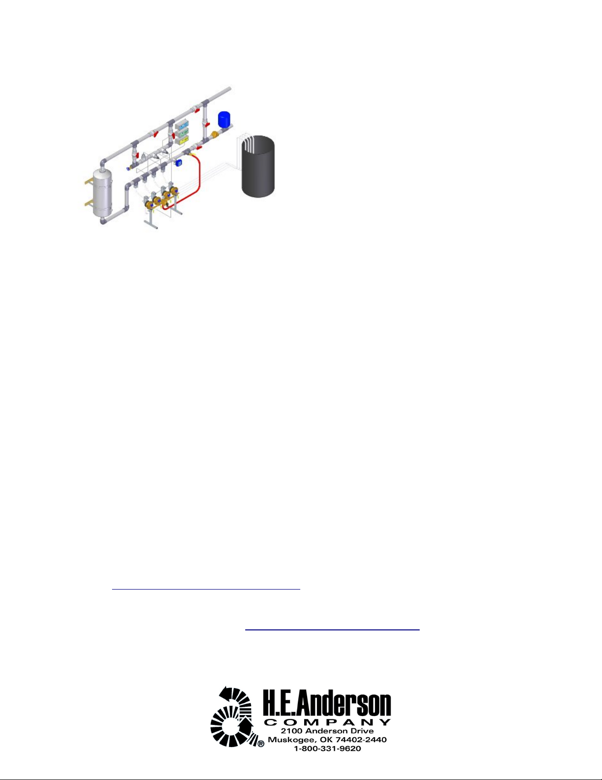
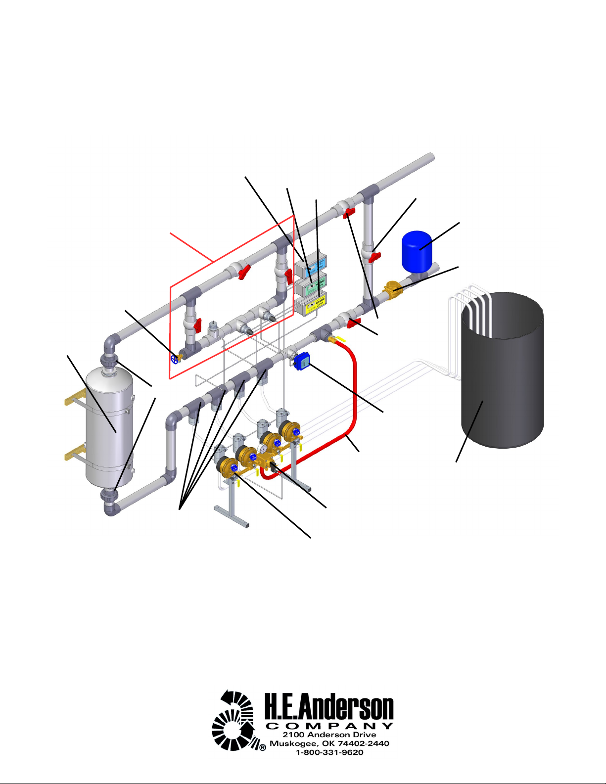
Installation Example
JP161-4 J Plus Injector with E-1S EC Monitor and P-2S pH Monitor
2
J Controller
EC Monitor
pH Monitor Bypass Val e
Bypass
Isolation
Val es
Bypass for pH and EC sensors.
Blend Tank
Capti e Air Tank
Backflow Pre enter
Pumpers and Manifold
Pilot Val e
Stock Chemical Solution Tank
Water Meter
Manifold Water
Supply Line
Injection Point Fitting
Check Val es
Boiler Drain
Unions

Warnings and Cautions
WARNING! Always appropriate
protecti e equipment (goggles,
protecti e clothing, respirator
etc.) when working with
chemicals and obser e all rele ant
guidelines and laws.
Set up your controller before
starting up your system. Refer
to the J Plus Controller
manual. Controllers are often
shipped with proper settings already
entered.
Store protective clothing and
accessories in a location away
from the injector so that they
may be donned before
approaching the equipment.
Do not store chemicals in
tanks where the le el will be
more than just a few feet
abo e the discharge point of
the pumpers. If you ha e ery large solution
storage tanks you should use them to fill
smaller “day tanks”. This will eliminate the
chance of large quantities of chemicals
draining into your watering system.
WARNING! Water hammer
destroys diaphragms. Damage
caused by water hammer is
not co ered under warranty.
WARNING! Ne er allow the
unit to freeze! Damage due to
freezing is not co ered by the
warranty.
Never transfer the suction line
of a feeder pumping a strong
acid or alkali to a container of
water. This can generate
dangerous heat which may destroy your
pumper and plumbing.
IMPORTANT! The waste line
must exit to atmospheric
pressure and must not be
ele ated or restricted in any
way.
WA NING! Connecting the
flow sensor incorrectly can
damage the flow sensor
electronics.
3

Installation Order of Components:
Install the components in the following order. They are ordered starting with the upstream direction. Only J
System Components are included in this section.
1. Manifold water supply 'Tee' or saddle
2. Water Meter
3. Injection Point Fittings
4. Blend tank
5. Sensor loop (if applicable)
Installation Considerations:
•Install the injector system in a bypass. This allows the injector to be isolated for ser ice while allowing
the water line to continue to supply water.
•Ensure all water to be treated flows through the water meter. The injector system will not function
properly if only part of the water flows through the water meter.
•Install unions on each side of the blend tank so the tank can be replaced or re-situated without
completely redoing the plumbing.
•If the stock solution tank is large, install a smaller “day tank” to supply the injector. In case of a
malfunction or leak the amount of chemical spilled will be reduced.
•Any on-off water al e should be installed downstream from the blending tank. This will insure that the
system injection point will always be pressurized, making siphoning of chemical unlikely.
•Suction lines may be plumbed with rigid PVC piping for a neater installation.
•Read the specific installation guidelines for your exact water meter. Different types of water meters ha e
different installation requirements.
•Check local codes for back-flow pre ention requirements.
•Capti e air tanks are recommended to reduce damage caused by water hammer.
•Injection point fittings can be installed up to 45º from ertical. See pumper manual for more information.
•The injector can be installed into se eral different pipe sizes. Consult a professional plumber or irrigation
ser ice to determine proper size for your application.
EC and pH Monitors
•Install EC and pH sensors in a three al e bypass loop so they can be isolated for ser ice.
•In the bypass loop for pH and EC sensors, the sensors are installed below water line to ensure they are
ne er dry and to reduce contact with air in lines.
•In the sensor bypass loop, partially close the main line al e so some water flows past the sensor.
•Install a boiler drain on the sensor bypass loop so samples can be taken and so pressure can be
relie ed when ser icing sensors.
•NOTE: Do not let the pH probe become dry. If the pH probe is allowed to dry out it will be damaged and
no longer function properly requiring replacement.
Location & ccess
•The injector should be out of the way, yet accessible
•If your water supply is from a municipal or public water line, you should comply with local codes.
•If your watering system is connected to a public or potable water source, a backflow pre enter should be
installed so that no backward flow of treated water into potable supplies or public mains can occur.
Contact your local water authority for appro ed de ices and recommendations to insure that your
installation meets their standards.
•Install the system neatly and with room for easy maintenance access.
Environment
•Freezing can cause expensi e damage, e en during storage if the measuring unit and pumpers ha e
not been properly drained.
4

•A drain should be a ailable close to the manifold. The unit discharges approximately twice as much
water as chemical pumped. The drain line should be kept short, or expanded to a larger size for runs
longer than fifteen feet.
•It is recommended that the unit be installed indoors. The unit as well as plumbing fittings should be kept
out of direct sunlight.
Safety
•Do not permit access by children or pets. Most chemicals used to treat water can be dangerous.
•Pro ide and use safety equipment such as goggles, glo es, aprons, or anything common sense or
OSHA requires.
•Store protecti e clothing and accessories in a location away from the injector so that they may
be donned before approaching the equipment.
•Check with the manufacturer of the chemical for safety precautions for specific chemicals.
•Label chemicals and keep a supply of antidotes, neutralizing agents, and safety precautions handy. If
feeding acid, keep some baking soda (powdered and solution) nearby.
•If feeding dangerous or corrosi e chemicals, you should attach a drain line to the bleed al e on the
injection point fitting (standard capacity pumpers) or VMC module (high capacity pumpers) which drains
into a chemical resistant container.
•A chemical resistant container should be placed directly beneath the manifold and pumpers.
•Protect the injector from corrosi e apors with adequate entilation. Corrosion can sometimes attack
diaphragms from the back side, resulting in premature failure.
Water Hammer
•Water hammer can generate pressures up to 500 psi or more! This puts stress on the injector (and on
your entire water system), but it is especially destructi e to diaphragms.
•Water hammer can be a serious problem in installations with long pipe runs.
•Solenoid al es can cause water hammer.
•If water hammer could be a problem for your installation, install a suppressor such as an accumulator
(capti e air de ice) near your injector.
Water Quality
Solids in your water supply act as abrasi es and will wear away the water measuring mechanism. If you
ha e problems with solids, install a filter upstream of the injector and place pressure gauges before and after.
You can use the difference in pressure readings to tell when the filter is plugged up.
Installation
1. Read and understand all the considerations and warning discussed in this guide.
2. Refer to the installation drawing in this guide for information in assembling your system. If you are
unfamiliar with plumbing or working with the piping materials chosen, hire a professional plumber to do
the installation.
3. IMPORTANT! Most plumbers are unfamiliar with our equipment and should be monitored to see that
they are following our installation recommendations.
4. The injector can be installed into se eral different pipe sizes. Consult a professional plumber or irrigation
ser ice to determine proper size for your application.
5. The water line pipe size DOES NOT ha e to match the pipe size of the water meter. The water meter is
often a smaller diameter than what is used in the rest of the irrigation system.
6. Plan the routing of the pipe for the injector system in ad ance.
7. Properly support all piping making sure there is not strain on any plumbing fittings.
8. Build or choose an appropriate place to house the injection system.
9. Begin at the upstream end and install all piping necessary for the injector system.
10. Start by installing a backflow pre enter on the water supply line.
11. Next install a capti e air tank.
5

12. Install appropriately sized 'tee' for bypass.
13. Install one of the al es which isolates the injector.
14. Install 'tee' which supplies water to the manifold.
15. Before installing the meter, flush the system to remo e metal flakes and other debris from the plumbing.
You should also flush the line that supplies the pilot al e/manifold before connecting it to the al e.
16. Install water meter. Make sure to read specific manual for your water meter. Different meters ha e
different installation requirements. All manuals can be found on the H.E. Anderson website.
17. NOTE: Strain on the water meter can interfere with operation and lead to water meter failure. Adjust the
piping to make sure no additional forces are acting on the water meter.
18. Install the appropriate number of 'tees' for injection point fittings. Consider future expansion possibilities
when choosing how many 'tees' to install. It is easy to plug a tee but hard to install an extra at a later
time.
19. Install blend tank with unions on either side. Make sure blend tank is properly secured to the floor, wall
or other suitable structure.
20. Install 'tee' for probe bypass loop is applicable.
21. Note: probe bypass loop does not ha e to be the same diameter pipe as the main water line. Not all
water must flow through probe bypass loop.
22. Install probe bypass al e and another tee making sure to lea e enough room in between for probe
tees.
23. Install al es to isolate probe loop below tees.
24. Install elbow, tee and probe tees in probe loop.
25. Install boiler drain in probe loop.
26. Install downstream injector isolation al e.
27. Install injector isolation al e and tee to compete injector bypass.
28. Install manifold close to injection point fittings. Properly bolt manifold to floor or wall.
29. NOTE: See manifold manual for complete information on installing the manifold.
30. Install injection point fittings into tees on water line.
31. Flush water line before proceeding. The probe loop can be closed off if probes are not installed.
32. Do not connect the supply line to the pilot al e/manifold before flushing the system.
33. Install pumpers on manifold. Be sure to include gasket between pumpers and manifold.
34. NOTE: See pumper manual for complete information on installing the pumpers.
35. Connect manifold supply from tee to manifold.
36. NOTE: Wait to install the manifold drain line until after the manifold is erified to work properly.
37. Supply water to system and check for leaks. Fix all leaks promptly to keep water off injection system and
to keep area around injector neat and easy to work around.
38. NOTE: Install probes after water has been supplied to the system. The pH probe cannot be left dry. The
pH probe will be damaged and must be replaced if it is allowed to dry out.
Electrical Connections
1. NOTE: Make wiring connections after plumbing is complete.
2. Refer to the manual Series J Plus Pumper Controllers for the terminal locations. The flow sensor and
al e outputs should be connected before wiring the power connections.
3. WARNING! Connecting the flow sensor incorrectly can damage the flow sensor electronics.
4. The terminals on the flow sensor terminal block are labeled 1, 2, & 3, both on the terminal board and on
the sensor cable. Be certain to match numbers when connecting these wires. If you need a longer cable,
use the color coding to be sure that these connections are correct.
5. The manifold al e terminals are numbered on the 4-output terminal block. On the 2-output model, al e
#1 is on the left side.
6. NOTE: On 2-output models the sensor terminal block is detachable which makes connecting the cable
much easier.
Setting the Controllers
Set up the controller before starting up the system. Refer to the J Plus Controller manual.
6
Initial Check-Out
1. With the water off, apply power to the electronic controller. After a few seconds the display should
indicate OFF.
2. Turn the water on slowly and let all lines and blend tank fill with water. Intermittent discharges of water
from the waste line should be obser ed.
3. Turn off the water to stop the injector.
4. Once the manifold is confirmed to be working properly, install the drain line from the manifold to the
drain. Make sure the line does not increase in ele ation and does not contain and kinks or sharp bends
that could restrict flow.
Start-Up
1. Install the suction strainer / foot al es in the solution concentrate tanks. If installing as a bulkhead
fitting, install about 2" abo e the bottom of the tank to pre ent the injector from drawing in sediment
which may collect on the bottom of the tank. Connect the suction lines from the chemical container to the
lower connection of the al e modules.
2. Connect the discharge lines between the al e module and injection point fittings. Set dials on the
pumpers to the number calculated to gi e the desired feed.
3. Fill your concentrate tanks and restart your injector.
4. Prime pumps by following instructions in controller manual.
5. NOTE: Watch out for leaks, especially when pumping acid. Fix all leaks immediately to a oid chemical
spills and to keep injector and area clean and safe.
6. Injector system should now be operational.
Maintenance
•The meter and electronic controller portion of your injector system normally require no maintenance.
There is no reason to disturb these components except to ser ice them when a problem arises.
•See the pumper manual for information on maintaining your pumpers and fittings.
•The chemical concentrate solution should be kept clean, fresh and thoroughly mixed.
•Your solution tank should be co ered, but must be ented with a small ent hole to atmosphere.
Otherwise the injector will draw a acuum on the solution container and quit functioning properly.
•Periodically clean the solution container. To pre ent loss of prime, transfer the suction line of the injector
to another container of the same solution during cleaning. Use caution appropriate to the chemical.
•Ne er transfer the suction line of a feeder pumping a strong acid or alkali to a container of water.
This can generate dangerous heat which may destroy your pumper and plumbing.
Storage
•If an injector will not be used for a long period, you should remo e it from ser ice.
•Flush the pumper and chemical al es, either by pumping water through the unit (if not feeding acid, see
below) before remo ing it or by rinsing after remo al.
•Tape the al e openings closed while still wet. This protects the seals and pre ents insects from
plugging the openings.
•Drain the unit completely to pre ent damage by freezing water still inside.
Trouble Shooting
If you suspect there may be a problem with your unit please read the following section carefully. DO NOT
DISASSEMBLE ANY PART OF YOUR SYSTEM until you ha e determined the exact problem, and then do it
carefully, according to instructions. Many small and easily corrected problems are greatly aggra ated by not
heeding this warning. Table 4 in the Series J Plus Pumper Controllers manual gi es some common problems
and tells how to correct them. Call the factory if you ha e questions about what you need to do.
There are two basic categories of problems; pumper problems and control problems. If you are getting flow
indication and regular cycles of waste water from the pilot al e you can be irtually certain the controller and
pilot al e are working properly. Table 1 in the Pilot Valve & Manifolds manual gi es some possible conditions
along with probable causes and suggested action. If you cannot determine the problem, call our factory at the
7

number listed in the front of this manual.
Checking the Meter Sensor
You ha e probably already obser ed the red LED indicators mounted on the sensor circuit board which is
housed in the clear housing atop the water meter. Checking these can quickly pinpoint some problems.
•The power LED will be lit whene er power to the controller is on and properly functioning (it displays and
responds to key presses). If not lit, there is a problem with the sensor board or, more likely, with the
cable between meter and controller.
•The second LED should light with each pulse from the sensor. It should be blinking whene er water is
flowing. If this is not happening, refer to the instructions for your meter for more information.
Pumper and Diaphragm Problems
See your pumper manual(s) for information on ser icing your pumpers.
Requirements for Proper Operation
•Minimum line pressure of 30 psig, measured on the downstream side of the injector. If you do not ha e a
pressure reading of 30 pounds at the pressure gauge on top of the unit, then you do not ha e enough
pressure. If the water is flowing out to an open tank or onto the ground, there will probably not be
sufficient back pressure to meet the 30 psig requirement e en if there is much greater pressure (e.g. 50
psig) on the inlet. This is the most common cause of erratic operation. In this situation you should install
a al e and pressure gauge downstream from the unit. Close the al e until the gauge reads 30 psi or
greater.
•The flow rate should be within the range of your flow meter. (See Table 1 in your meter manual for flow
range information).
•The pumpers should not exceed 35 strokes per minute. Running the injector system faster than 35
strokes per minute can result in premature failure of pumpers. Pumpers also might not ha e enough
time to completely fill with solution between strokes causing incorrect injection rates.
•The manifold discharge line and any tubing attached must open to “daylight” and go directly to a drain.
Do not obstruct or ele ate the line at any point. If a long line is needed, it should be expanded to a larger
size. Put an air ent or gap between the primary and the extended line.
•Too much chemical feed is usually not caused by a malfunction. It is usually due to siphoning or gra ity
flow of chemical through the feeder during periods of zero pressure on the system. The system shutoff
al e should be downstream of the system to maintain pressure at all times and the chemical le el in
storage tanks should not be abo e the injection point fitting.
•Do not store chemicals in tanks where the le el will be more than just a few feet abo e the
discharge point of the pumpers. If you ha e ery large solution storage tanks you should use
them to fill smaller “day tanks”. This will eliminate the chance of large quantities of chemicals
draining into your watering system.
8

RATIO:FEEDER® LIMITED WARRANTY
WH T IS COVERED
The H.E. Anderson Company of Muskogee, Oklahoma, will make any necessary repairs and/or replace any
parts of any Ratio:Feeder® product made necessary because of defects in materials or workmanship for fifteen
months from date of manufacture. Warranty repairs and/or replacements will be performed without charge to the
owner by H.E. Anderson Company within a reasonable time after prepaid deli ery of the defecti e product to the
H.E. Anderson Company, 2100 Anderson Dri e, Muskogee, Oklahoma 74403.
WH T IS NOT COVERED
This warranty specifically excludes failure of any parts or materials caused by chemical attack or damage
caused by operation abo e rated capacity or pressure. Further, this warranty does not co er wear or failure
caused by sand or other foreign materials which may be found in water that is passed through our products, or
damage caused by freezing or exposure to water temperatures abo e 60°C (140°F).
This warranty does not co er damage caused by failure to follow prescribed installation instructions and
limitations issued by H.E. Anderson Company. In addition, this warranty does not co er ser ice adjustments,
repairs, or replacements caused by misuse, negligence, alteration, accident, or lack of specified maintenance.
This warranty does not co er damage to electronics from water, oltage spikes, or lightning strikes.
This warranty does not co er components used by, but not manufactured by H.E. Anderson Company, in the
manufacture of our products except to the extent of said component manufacturer's warranty.
This warranty specifically excludes liability for consequential damages or for charges for labor or expense in
making repairs or adjustments, or losses of time or incon enience.
This warranty gi es you specific legal rights and you may also ha e other legal rights which may ary from
state to state. H.E. Anderson Company does not authorize any person to create for it any other obligation or
liability in connection with these products. ANY IMPLIED WARRANTY APPLICABLE TO THESE PRODUCTS IS
LIMITED TO THE DURATION OF THIS WARRANTY. H.E. Anderson Company shall not be liable for
consequential damages resulting from breach of this written warranty.
NOTE: Some states do not allow limitation on how long an implied warranty will last or the exclusion of
limitations of incidental or consequential damages, so the abo e limitations or exclusions may not apply to you.
WH T TO DO IF THERE IS QUESTION REG RDING W RR NTY
1. Promptly notify the consumer ad iser at H.E. Anderson Company by telephone at 800-331-9620 or 918-687-
4426.
2. Confirm the report in writing (or ia FAX at 918-682-3342) to the H.E. Anderson Company, stating the
circumstances surrounding the problem.
PURCH SER'S OBLIG TION
3. Purchaser must gi e H.E. Anderson Company immediate written notice on disco ery of defect.
4. Purchaser must pay for shipment of the defecti e product to the H.E. Anderson Company, 2100 Anderson
Dri e, Muskogee, Oklahoma 74403.
9
This manual suits for next models
1
Table of contents
Other H.E. Anderson Laboratory Equipment manuals


Popular Laboratory Equipment manuals by other brands

Labconco
Labconco Purifier 3951400 user manual

PRO Scientific
PRO Scientific Bio-Gen PRO200 operating manual

Hach
Hach PHC745 user manual

Memmert
Memmert HPP 108 operating instructions

ThermoFisher Scientific
ThermoFisher Scientific Sorvall Legend Micro 17 instruction manual

bioMerieux
bioMerieux MINI VIDAS user manual


feedback
feedback MS150 Getting started

Cuisinart
Cuisinart CS-6 SERIES Instruction booklet

Owlstone
Owlstone 90-0322 Series installation instructions

Cascade
Cascade CVO-2 Installation & operation manual

Germfree
Germfree Z Series user manual

Cost Effective Equipment
Cost Effective Equipment APOGEE 300 owner's manual