Owlstone 90-0322 Series User manual

90-0322-AAA OHG Sub-Unit Installation Instructions 20th Nov 2012
© 2012 Owlstone Ltd Proprietary and Confidential Page 1 of 14
90-0322-AAA OHG Sub-Unit Installation Instructions
Issue/Version
Date
Author
Details
AAA
20/11/2012
Graham Newell
Original
Overview
This document describes how to install additional OHG sub-units into an existing GEN-SYS system.
Table of contents
Section 1 - Note on safety.......................................................................................................................... 2
Section 2 - Materials and tools................................................................................................................... 2
Section 3 - Overview of procedure............................................................................................................. 3
Section 4 - Disconnect power + air from the GEN-SYS rack..................................................................... 4
Section 5 -Removing an OVG-4 sub-unit (optional step).......................................................................... 5
Section 6 - Installing a Quick Connect in GEN-SYS.................................................................................. 8
Section 7 - Preparing the RS-485 cable .................................................................................................... 9
Section 8 - Installing the OHG ................................................................................................................. 10
Section 9 - Fit the water bottle bracket assembly.................................................................................... 12
Section 10 - Connecting the water bottle ................................................................................................... 13
Section 11 - Connecting the hygrometer.................................................................................................... 14

90-0322-AAA OHG Sub-Unit Installation Instructions 20th Nov 2012
© 2012 Owlstone Ltd Proprietary and Confidential Page 2 of 14
Section 1 - Note on safety
Customers are expected to make their own assessment of COSHH / chemical safety
before following this procedure. Customers should also consider undertaking a risk
assessment before attempting procedures described in this document.
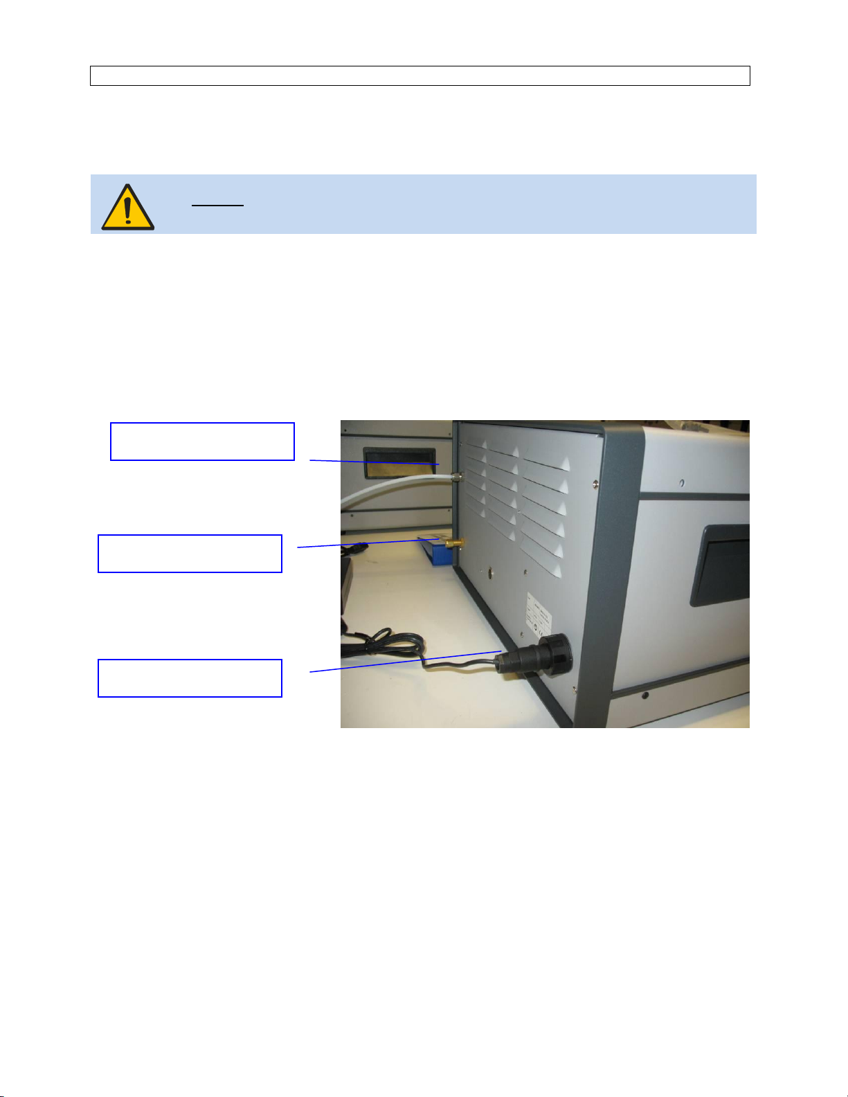
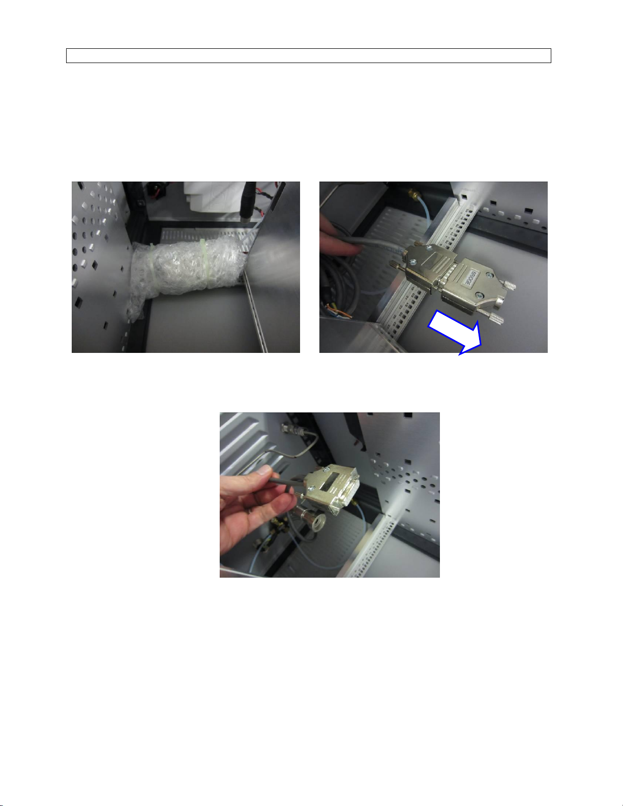
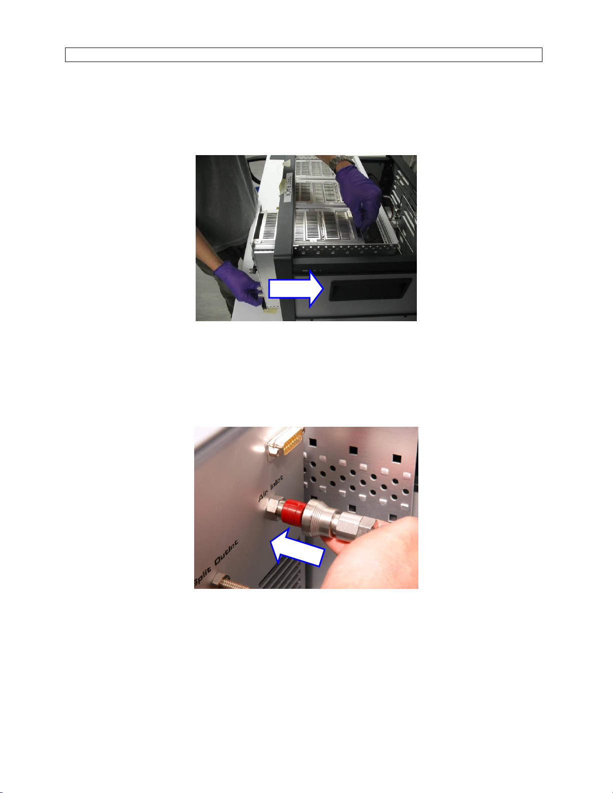
Always physically disconnect Inlet Air, and power from the rear of the GEN-SYS rack
before following this procedure (section 3 of this guide explains how to do this).
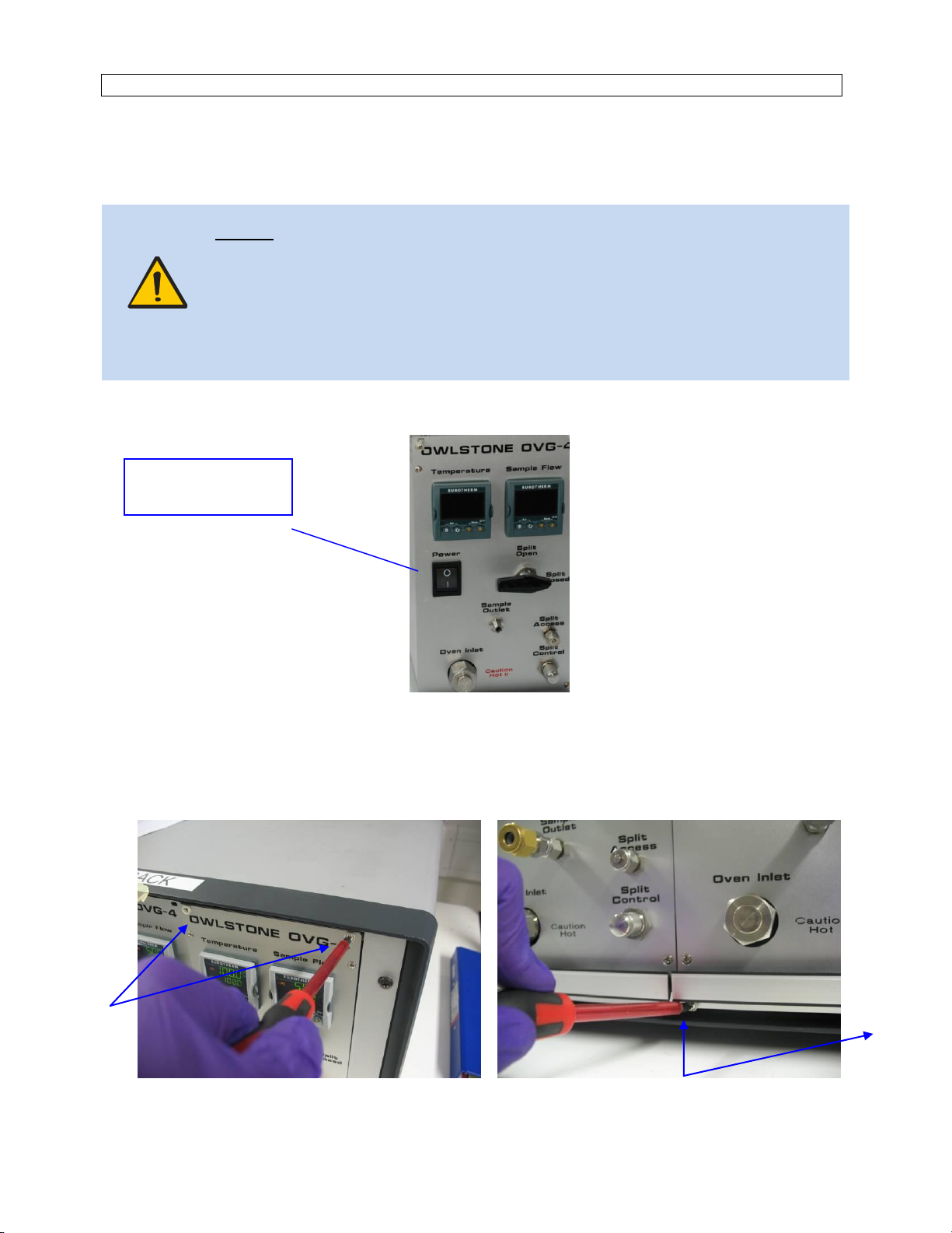
Always ensure sub-units are switched off before removing them from the GEN-SYS rack.
Section 2 - Materials and tools
If a customer purchases an OHG they are supplied with the following items..
00-0006 1 Owlstone Humidity Generator (OHG)
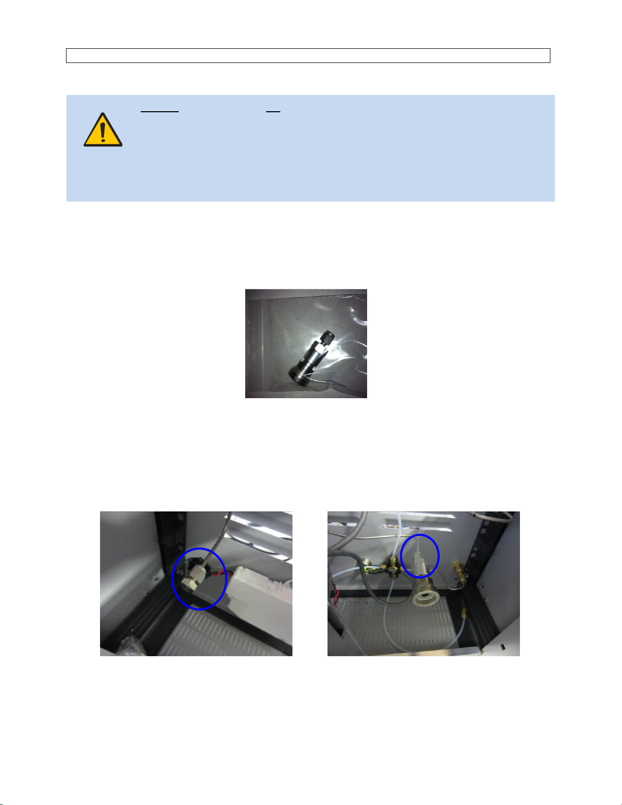
50-0081 1 Quick connect body, Swagelok 1/8”
01-0228 1 Bracket assembly (for holding bottle)
51-0020 6 M3 x 6mm, screws to connect bottle bracket to GEN-SYS rack
01-0160 1 Bottle cap and 2micron diffuser assembly
50-0158 1 Bottle, 500ml, pressure rated
----------- 2 Pipe assemblies to connect bottle to OHG
50-0258 2 1/8” Swagelok Nut
50-0282 2 1/8” Swagelok Ferrule
50-0543 1 Dew-Point Hygrometer
----------- 1 Pipe assembly to connect output of OHG to Easidew Hygrometer
90-0027 1 Decontamination certificate
---------- 1 Michell Instruments User Guide
Tools required:
1 x 5/8“ spanner
2 x 7/16” spanner
Philips screwdriver, No. 1
A pair of side cutters

90-0322-AAA OHG Sub-Unit Installation Instructions 20th Nov 2012
© 2012 Owlstone Ltd Proprietary and Confidential Page 3 of 14
Section 3 - Overview of procedure
Disconnect power, air and RS-485 cabling from the GEN-SYS rack, see section 4
Remove roof panel from rack, see section 5
Because of the external water bottle the OHG must be mounted in the right-hand position as
shown below. If you need to remove an OVG already mounted in this position see section 5
Figure-1: OHG position
Fit the Quick Connect supplied with the OHG, see section 6
Prepare the RS-485 cable, see section 7
Install the OHG, see section 8
Fit the water bottle holder, see section 9
Connecting the water bottle, section 10
Connecting the hygrometer, section 11
The OHG must be located
in the right-hand position

90-0322-AAA OHG Sub-Unit Installation Instructions 20th Nov 2012
© 2012 Owlstone Ltd Proprietary and Confidential Page 4 of 14
Section 4 - Disconnect power + air from the GEN-SYS rack
This section describes how to disconnect the GEN-SYS rack from air, exhaust and power services.
Warning: Inlet gas line pressure must be vented before following this procedure.
1) Vent the gas supply line that provides pressure to the GEN-SYS system. Do not proceed unless
pressure has been vented from this line.
2) Using a 9/16” spanner disconnect the inlet gas line from the rear of the GEN-SYS system.
3) If in use, using a 9/16” spanner disconnect the exhaust line from the rear of the GEN-SYS system
4) The DC power connection is unscrewed by hand.
Figure 2: Rear panel of GEN-SYS rack
Disconnect Air Supply
Disconnect Exhaust
Disconnect DC Power

90-0322-AAA OHG Sub-Unit Installation Instructions 20th Nov 2012
© 2012 Owlstone Ltd Proprietary and Confidential Page 5 of 14
Section 5 - Removing an OVG-4 sub-unit (optional step)
To improve access it is often more convenient to remove any pre-existing OVG-4 sub-units from the GEN-
SYS rack. This is not essential and may impact the users COSHH evaluation.
Warning: The user is responsible for considering all chemical safety implications / COSHH
before following this procedure.
Always disconnect DC power, exhaust and gas supply from the rear of the GEN-SYS rack
before following this procedure.
Always consider chemical safety before following this procedure.
1) Switch off power to the unit
Figure 3: OVG-4 front panel
2) Allow the OVG-4 to cool down to room temperature
3) Unscrew and remove the 4x screws from the front panel of the OVG-4 as shown below
Figure 4: photograph showing the 4x screws used to mount the OVG-4
Switch off power to
the unit here

90-0322-AAA OHG Sub-Unit Installation Instructions 20th Nov 2012
© 2012 Owlstone Ltd Proprietary and Confidential Page 6 of 14
4) Remove the ‘roof’ panel from the rack
Unscrew the 4x screws shown below. The roof panel can then be lifted off.
Figure 5: removing the roof panel
5) Disconnect DC power and gas supply
Both DC power and gas supply fittings are removed by hand from the rear of the OVG-4.
The DC power connector is removed by pulling gently. The gas supply QC is removed by sliding the
tapered end of the quick-connect towards the rear of the OVG-4
Figure 6: Disconnect DC power cable Figure 7: Disconnect gas line ‘quick-connect’

90-0322-AAA OHG Sub-Unit Installation Instructions 20th Nov 2012
© 2012 Owlstone Ltd Proprietary and Confidential Page 7 of 14
6) Disconnect the exhaust line
Using a 7/16” spanner unscrew the 1/8” Swagelok fitting on the rear of the OVG-4.
Figure 8: Disconnecting the exhaust
7) Carefully remove the OVG-4 from the rack
Use both hands to carefully slide the OVG-4 out of the GEN-SYS rack.
Figure 9: Removing an OVG-4 from the GEN-SYS rack

90-0322-AAA OHG Sub-Unit Installation Instructions 20th Nov 2012
© 2012 Owlstone Ltd Proprietary and Confidential Page 8 of 14
Section 6 - Installing a Quick Connect in GEN-SYS
Warning: Swagelok fittings will leak if fitted incorrectly. Owlstone will not take any
responsibility for incorrect fitting of Swagelok fittings by the end user.
The user must undertake a risk assessment before following this procedure. The user is
responsible for assessing chemical safety, COSHH and other risk implications.
If the user requires the GEN-SYS system to be leak tight it must be tested after assembly.
Please contact Owlstone for technical support regarding leak testing.
1) Prepare materials
A Swagelok Quick Connect is supplied with your OHG (Owlstone p/n 50-0081).
Two 7/16” and a 5/8” spanner are required for this procedure.
Figure 10: Quick connect
2) Remove Swagelok cap, fit Quick Connect
Remove the Swagelok cap using the two 7/16” spanners before installing the quick connect. Swagelok
fittings must be tightened by hand before turning an additional 1x half turn using a 7/16” spanner.
Do not over-tighten.
Figure 11: Remove the cap Figure 12: Install the quick connect

90-0322-AAA OHG Sub-Unit Installation Instructions 20th Nov 2012
© 2012 Owlstone Ltd Proprietary and Confidential Page 9 of 14
Section 7 - Preparing the RS-485 cable
If the user needs RS-485 communication capability then cabling needs to be prepared as shown below
Firstly, un-wrap & un-strap the spare cables.
Next remove the “bridge” or “plug” to leave the 15-way connector ready to connect to the OHG.
Figure 13: RS-485 cables as supplied Figure 14: Remove “bridge” or “plug”
Figure 15: Cable ready to connect to the OHG

90-0322-AAA OHG Sub-Unit Installation Instructions 20th Nov 2012
© 2012 Owlstone Ltd Proprietary and Confidential Page 10 of 14
Section 8 - Installing the OHG
Installing the OVG-4 sub-unit follows the procedure described in section 4 in reverse.
1) Mount the OVG-4 sub-unit in the GEN-SYS rack
Figure 16: Mounting an OVG-4 sub-unit
2) Connect quick connect to the rear of the OVG-4 as shown below.
Pushing the valve firmly until a click is heard.
Figure 17: Connect Quick Connect Valve

90-0322-AAA OHG Sub-Unit Installation Instructions 20th Nov 2012
© 2012 Owlstone Ltd Proprietary and Confidential Page 11 of 14
3) Connect DC power cable
Connect the DC power cable to the power socket on the rear of the OVG-4 as shown below.
Figure 18: Plug power cable into socket
4) Connect the RS485 cable
Connect the RS-485 connector to the rear of the OHG as shown below, tighten the two screws.
Figure 19: Fitting the RS-485 connector
5) Replace the roof panel
Replace the roof panel and tighten the 4x screws. See section 5.4
6) Re-connect DC power, Air, Exhaust to the rear of the GEN-SYS system
Refer to Section 4.

90-0322-AAA OHG Sub-Unit Installation Instructions 20th Nov 2012
© 2012 Owlstone Ltd Proprietary and Confidential Page 12 of 14
Section 9 - Fit the water bottle bracket assembly
The black rivets on the right hand side of the rack need to be removed before the bottle bracket assembly
can be attached to the rack. They can easily be removed by hand.
Figure 20: rivets Figure 21: Screws required to fasten the bracket
Using a screwdriver and the screws provided fasten the bracket.
Figure 22: fixing the bracket
The bracket is now secured to the rack.
Figure 23: the bracket is attached!
Remove the 4x rivets

90-0322-AAA OHG Sub-Unit Installation Instructions 20th Nov 2012
© 2012 Owlstone Ltd Proprietary and Confidential Page 13 of 14
Section 10 - Connecting the water bottle
The first step is to connect the two stainless steel pipe assemblies to the top of the bottle.
The two pipes will only fit one way around as shown below. The Swagelok female miniature quick
connects have a ‘collar’ which is pulled in order to insert the male stub fitting.
Once you have connected the two pipe assemblies to the top of the bottle you simple connect the other
end of each pipe assembly to the OHG using a 7/16” spanner.
Figure 24: attached the bottle Figure 25: attaching the pipes
Connect tubing from the connector on the top of
the bottle marked DRY to the outlet port on the
OHG marked Dry Air Outlet.
Connect tubing from the connector on the top of
the bottle marked WET to the inlet port on the
OHG marked Wet Air Inlet.
** WARNING **
If these two pipes are inadvertently connected
the wrong way around you may drive water
into the OHG and hygrometer!
Figure 26: attaching the pipes
Female miniature
quick connect
Male stubb

90-0322-AAA OHG Sub-Unit Installation Instructions 20th Nov 2012
© 2012 Owlstone Ltd Proprietary and Confidential Page 14 of 14
Section 11 - Connecting the hygrometer
A short length of stainless steel tube is supplied to allow the user to connect the hygrometer to the Wet
Air Outlet as described below.
Depending on user requirements you may choose to fit the hygrometer elsewhere in your pneumatic
circuit.
Figure 27: attaching the hygrometer Figure 28: attaching the connector
Figure 29: finished!
1/8” Swagelok tube fittings should be
tightened “finger tight + a further half a
turn” using a 7/16” spanner.
Locate the sensor connector into the Humidity
Sensor socket at the front of the OHG. Turn
‘collar’ clockwise until resistance is felt.
Table of contents
Other Owlstone Laboratory Equipment manuals
Popular Laboratory Equipment manuals by other brands

Leica
Leica RM2235 user manual

Renfert
Renfert BASIC eco quick start guide

Velp Scientifica
Velp Scientifica AREX 5 instruction manual

Agilent Technologies
Agilent Technologies Intuvo 9000 Installation and First Startup

EKO
EKO ASI-16 instruction manual

Helmer Scientific
Helmer Scientific i.Series Service and maintenance manual