Mocom SUPREME 17 User manual

CEFLA S.C. Via Selice Prov.le 23/A - 40026 Imola (BO)
After Sales Service
tel. +39 0542 653566 -
Fax +39 0542 653596
E-mail: service.sterilization@cea.it
Technical manual
code 97071257 rev. 00
SUPREME (17-22-28)
FUTURA (17-22-28)
CLASSIC (17-22-28)
Series 2019


97071257
Rev. 00
2019-03
EN

Sterilizers SUPREME - FUTURA - CLASSIC (17-22-28)
- TECHNICAL MANUAL
2
EN
ITALIANO
Page left blank intentionally

Sterilizers SUPREME - FUTURA - CLASSIC (17-22-28)
- TECHNICAL MANUAL
EN
CONTENTS
3
CONTENTS
1. GENERAL WARNINGS ...................................................................................................................................... 4
1.1. FOREWORD ................................................................................................................................................. 4
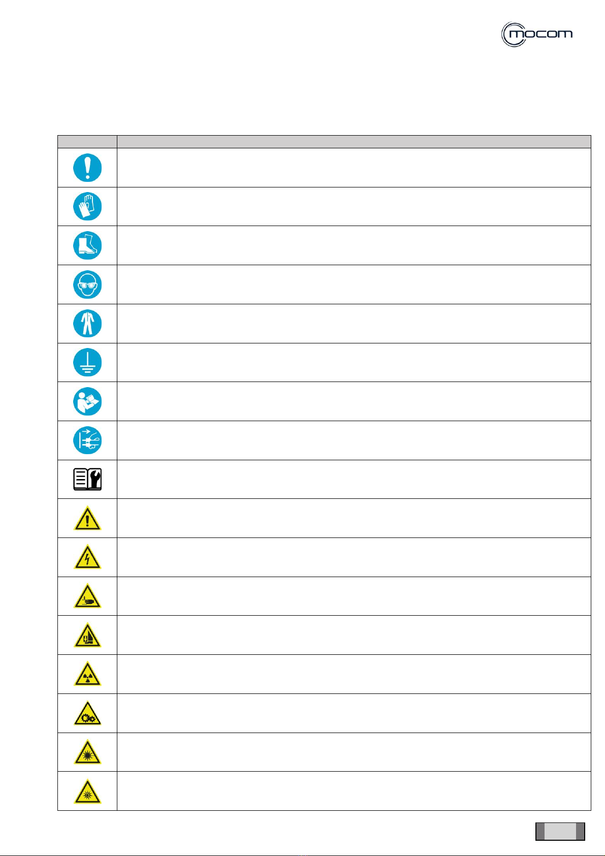
1.2. SAFETY INSTRUCTIONS.............................................................................................................................. 5
2. PACKING AND TRANSPORT............................................................................................................................. 7
2.1. TRANSPORT AND STORAGE ...................................................................................................................... 7
2.2. DAMAGE DURING SHIPMENT...................................................................................................................... 8
3. GUIDELINES - SAFETY TEST - VALIDATION (IF REQUIRED) .......................................................................... 9
3.1. CHECKS REQUIRED FOR THE DRAFTING OF CONFORMITY REPORT .................................................... 9
3.2. CONFORMITY REPORT ..............................................................................................................................10
3.3. APPLICATION EXAMPLE WITH INSTRUMENT SECUTEST SIII+ ON STERILIZER OR
THERMODISINFECTOR...............................................................................................................................11
3.4. INDICATIONS FOR THE SOLUTION OF NON-CONFORMITIES DETECTED IN THE TEST........................13
4. FUNCTIONING................................................................................................................................................. 14
4.1. PRE-HEATING .............................................................................................................................................14
4.2. WARM UP ....................................................................................................................................................15
4.3. 1st VACUUM PHASE....................................................................................................................................17
4.4. 1st PRESSURE RISE ...................................................................................................................................20
4.5. 2nd VACUUM PHASE...................................................................................................................................22
4.6. 2nd PRESSURE RISE ..................................................................................................................................24
4.7. 3rd VACUUM PHASE ...................................................................................................................................26
4.8. 3rd PRESSURE RISE...................................................................................................................................28
4.9. STERILIZATION PROCESS .........................................................................................................................30
4.10. DISCHARGE ............................................................................................................................................32
4.11. DRYING....................................................................................................................................................34
4.12. PRESSURE LEVELLING ..........................................................................................................................36
5. SERVICE MENU............................................................................................................................................... 38
5.1. AUTOCLAVES WITH ROOT VALVE REF.7A24, 7A34, 7A44, 7A54..............................................................38
5.1.1. COMPONENT TEST –FUNCTIONAL CHECKS ON SOLENOID VALVES/OTHER COMPONENTS......41
5.2. AUTOCLAVES WITH ROOT VALVE REF. 7A20, 7A21, 7A22, 7A23, 7A30, 7A31, 7A32, 7A33, 7A40, 7A41,
7A42, 7A43, 7A50, 7A51, 7A52, 7A53...........................................................................................................49
5.2.1. COMPONENT TEST –FUNCTIONAL CHECKS ON SOLENOID VALVES/OTHER COMPONENTS......53
5.3. FUNCTIONS AVAILABLE ONLY IN THE APP easyaccess ...........................................................................65
6. ALARMS / ERRORS / WARNINGS / TROUBLESHOOTING ............................................................................. 68
6.1. ERROR ALARMS - CODE “E”.......................................................................................................................68
6.2. FAULT ALARMS - CODE “A” ........................................................................................................................80
6.3. DANGER ALARMS - CODE “H”....................................................................................................................99
6.4. ACCESSORY ALARMS - CODE “S” ...........................................................................................................104
7. TECHNICAL SHEETS .................................................................................................................................... 107
7.1. TECHNICAL SHEET ST01 - STEAM GENERATOR (ON ALL MODELS) ....................................................107
7.2. TECHNICAL SHEET ST02 - MANIFOLD.....................................................................................................112
7.3. TECHNICAL SHEET ST03 - DOOR CLOSING UNIT ..................................................................................114
7.4. TECHNICAL SHEET ST04 - PRESSURE TRANSDUCER - SAFETY PRESSURE SWITCH.......................116
7.5. TECHNICAL SHEET ST05 - PT1 PROBE - CHAMBER TEMPERATURE READING...................................119
7.6. TECHNICAL SHEET ST06 - DOOR ADJUSTMENT....................................................................................121
7.7. TECHNICAL SHEET ST07 - CONDUCTIVITY SENSOR.............................................................................122
7.8. EV7 TECHNICAL SHEET - SOLENOID VALVE EV7 (PRESENT ONLY ON “SUPREME” MODEL).............123
7.9. VIBRATION PUMP UNIT TECHNICAL SHEET ...........................................................................................124

Sterilizers SUPREME - FUTURA - CLASSIC (17-22-28)
- TECHNICAL MANUAL
4
GENERAL WARNINGS
EN
1. GENERAL WARNINGS
1.1.FOREWORD
The device described in this manual is manufactured by CEFLA s.c. - via Selice Provinciale 23/A - 40026 Imola (BO)
Italia, which is the manufacturer, in compliance with the applicable European Directives detailed in the declaration of
conformity.
These technical instructions are addressed to the personnel in charge of repair and/or maintenance operations of
CEFLA s.c. equipment and contain all the necessary information.
CEFLA s.c. shall be responsible for the safety, reliability and efficiency of the equipment provided that:
installation, any modifications, settings or repairs are made by authorised technical personnel using CEFLA s.c.
original spare parts
In case of installation in medical locations: the electrical installation of the relevant location complies with IEC
60364-7-710:2002 Standards (Standards on electrical installations of medical locations) or with the equivalent
Standards in force in the country of installation
the equipment is used as outlined in User Manual
in case of installation of an X-ray unit: The room where the X-ray unit is installed complies with the official Directives
on protection from radiation in the country of use

Sterilizers SUPREME - FUTURA - CLASSIC (17-22-28)
- TECHNICAL MANUAL
EN
GENERAL WARNINGS
5
1.2.SAFETY INSTRUCTIONS
Information that draws the user’s attention to the need of preventing dangerous situations and ensuring the correct
and safe use of the device is reported in the text according to the following layout:
SYMBOL
DESCRIPTION
WARNING: General obligation
WARNING: It is mandatory to wear safety gloves
WARNING: It is mandatory to wear safety shoes
WARNING: Use eye protections
WARNING: Use protective clothing
WARNING: It is mandatory to ensure that there is an earth connection
WARNING: See the instruction manual
WARNING: Disconnect the device from the power mains
WARNING: See the technical manual
DANGER: It indicates a situation in which the failure to follow the instructions may lead to a fault of the
equipment or injuries to the user
DANGER: High voltage
DANGER: Crushing of hands
DANGER: Crushing of feet
DANGER: X-ray emission
DANGER: Moving parts
DANGER: Class 1 LASER radiation
DANGER: Class 2 light source.

Sterilizers SUPREME - FUTURA - CLASSIC (17-22-28)
- TECHNICAL MANUAL
6
GENERAL WARNINGS
EN
SYMBOL
DESCRIPTION
DANGER: Hot surface
DANGER: Biological risk
DANGER: Sharp objects
DANGER: Corrosive substances
DANGER: Flammable materials
DANGER: Tipping over
DANGER: Heavy object. Two persons are required
WARNING!
ALWAYS DISCONNECT power supply before performing any maintenance or cleaning operation.
The packed device must be handled using, where possible, suitable mechanical means (forklift, pallet
truck, etc.) and following the indications on the package.
In case of manual handling, the device must be lifted by several persons using the suitable available
means and, if possible, it must be moved with a truck or similar means.
Wear the proper protections.

Sterilizers SUPREME - FUTURA - CLASSIC (17-22-28)
- TECHNICAL MANUAL
EN
PACKING AND TRANSPORT
7
2. PACKING AND TRANSPORT
2.1.TRANSPORT AND STORAGE
Instructions on how to handle, store and open the package are given on the outside of the cardboard box.
These instructions must be carefully followed.
1) Transport and store only in the direction indicated by the
arrows
2) Do not overlap more than three units
3) Avoid collisions
4) Protect against humidity
5) The required storage conditions are indicated:
a) temperature from - +5° to +70° C
b) relative humidity from 20 to 80%
c) atmospheric pressure from 50 to 110 kPa
It is recommended to transport and store the device at a temperature not lower than that indicated on
the packing. A prolonged exposure to a low temperature can damage the device.
The packed device must be handled using, where possible,
suitable mechanical means (forklift, pallet truck, etc.) and
following the indications on the package.
In case of manual handling, the product must be lifted by two
persons using the suitable available means.
Once removed from the box, the device must be lifted by two
persons using the suitable available means and moved, if
possible, with a truck or similar means.

Sterilizers SUPREME - FUTURA - CLASSIC (17-22-28)
- TECHNICAL MANUAL
8
PACKING AND TRANSPORT
EN
2.2.DAMAGE DURING SHIPMENT
When the device is received, check the packing container for any damage suffered.
If the packages are found to be damaged on delivery, accept them with reserve by signing the delivery note and
indicating that the “CONTENTS ARE ACCEPTED BUT THEY NEED TO BE CHECKED”.
If the contents are actually damaged, notify the shipping agent and request insurance compensation for damage
within five work days. The claim is to be made by the person who commissioned the shipping agent. I.e.:
if the goods are delivered “carriage forward”, the receiver shall notify the shipping agent
if the goods are shipped “carriage free” or “free delivered”, the consigner shall notify the shipping agent and file a
claim for damages. In this case, CEFLA s.c. shall be informed as soon as possible.
The damaged parts returned to CEFLA s.c. for replacement shall be placed inside the same damaged package.
Return to CEFLA s.c. shall be “carriage free” (at the expense of the consigner), while shipment back to the customer
shall be at the expense of CEFLA s.c. (carriage free).

Sterilizers SUPREME - FUTURA - CLASSIC (17-22-28)
- TECHNICAL MANUAL
EN
GUIDELINES - SAFETY TEST - VALIDATION (IF REQUIRED)
9
3. GUIDELINES - SAFETY TEST - VALIDATION (IF REQUIRED)
Periodical checks to be carried out every year and checks after repair/updates/settings with reference to Standard
IEC 61010.
Safety standards for medical electrical equipment classified according to IEC 61010 in Class 1.
3.1.CHECKS REQUIRED FOR THE DRAFTING OF CONFORMITY REPORT
a) Visual inspection
The purpose of visual inspection is to ensure that the equipment in use still complies with the specifications
released by the manufacturer through the following checks:
condition of power cables and connectors
condition of earth cables and correct tightening
condition of covers
condition of electrical board protections and correct value of the fuses
conditions of warning plates
conditions of light and sound indicators (display, buzzer, etc...)
presence of liquid leaking out from ducts or on the bottom of the device
presence of the updated user manual in printed or electronic format
b) Electric measure test (to be carried out with special instruments)
Measurement of earth conductor resistance
Measurement of the device’s earth-leakage currents:
1) current under normal conditions
2) current under single failure conditions
Measurement of insulation resistance between network and earth conductor
c) Functional checks
Check the door opening and closing controls
Check the display and perform a test cycle

Sterilizers SUPREME - FUTURA - CLASSIC (17-22-28)
- TECHNICAL MANUAL
10
GUIDELINES - SAFETY TEST - VALIDATION (IF REQUIRED)
EN
3.2.CONFORMITY REPORT
CONFORMITY REPORT - Ref. Standard:
STANDARD
CLASS
Scheduled maintenance
IEC 61010
CL1
DEALER:
Unscheduled maintenance
DENTAL SURGERY Dr.:
DEVICE:
SERIAL NUMBER:
MEASUREMENT INSTRUMENT - MODEL:
S/N:
VISUAL INSPECTION
Conditions of:
power cables and connectors
earth cables and correct tightening
electrical protections
covers
warning plates
light indicators
OK
Presence of:
liquid leaking out from ducts or on the bottom of the device
user manual
ELECTRICAL SAFETY TEST
(MEASUREMENT POINT AND MAX VALUE)
MEASUREMENT OF EARTH CONDUCTOR RESISTANCE
Ω
OK
Earth conductor ≤ 0.1 Ω
MEASUREMENT OF EARTH-LEAKAGE CURRENT:
A
OK
1) under normal conditions ≤ 0.5 mA
2) under single failure conditions ≤ 3.5 mA
INSULATION RESISTANCE TEST - Test voltage = 500 Vdc
Ω
OK
Measurement between network and earth > 2 MΩ
VISUAL INSPECTION
•Door opening and closing controls
•Light indications and/or acoustic signals
OK
Notes:
FINAL EVALUATION:
OK
FAULT
DEALER:
TECHNICIAN:
DATE:
SIGNATURE:

Sterilizers SUPREME - FUTURA - CLASSIC (17-22-28)
- TECHNICAL MANUAL
EN
GUIDELINES - SAFETY TEST - VALIDATION (IF REQUIRED)
11
3.3.APPLICATION EXAMPLE WITH INSTRUMENT SECUTEST SIII+ ON STERILIZER
OR THERMODISINFECTOR
Measurement of earth conductor resistance
Measurement of earth-leakage current
Measurement of insulation resistance between network and earth
Disconnect power supply cable of the device and connect it to the relevant instrument socket (e.g.: SECUTEST
SIII+). Activate the device to be tested.
NOTE: the device under test must be on and must be pre-heated in advance through an operating cycle
of at least 30 minutes, until it reaches the operating temperature, as required by the Standard.
Select the type of test with reference to standard IEC 61010, from PC or tester screen. Follow the instructions
displayed with reference to the visual check and device data entry (e.g.: serial number).
Power up the device and select the Standard.
INITIAL SETTING
CONNECTIONS WITH THE MACHINE POINTS MUST BE KEPT FOR THE TESTS DESCRIBED
BELOW.
NOTE: follow the instructions requested by the control instrument.
E.G.: SECUTEST SIII+ instrument connection

Sterilizers SUPREME - FUTURA - CLASSIC (17-22-28)
- TECHNICAL MANUAL
12
GUIDELINES - SAFETY TEST - VALIDATION (IF REQUIRED)
EN
Connect the clamp to the frame at the point indicated in the following picture:
Metal foot [A]
WARNING: During measurement execution, hazardous voltage could remain in the device.
Press “Start” to start test sequences.
Depending on your instrument, you have to select all the tests indicated below:
A) measurement of earth conductor resistance
B) measurement of earth-leakage current
C) measurement of insulation resistance between network and earth
A) Measurement of earth conductor resistance (to be carried out after setting the test current of 25 Amperes in the
tester)
B) Measurement of earth-leakage current
Select the specific test on the tester:
“Earth conductor”: start the test; it must be carried out under single failure conditions (interruption of a network
conductor at a time) - (normal tester automatism)
C) Measurement of insulation resistance between network and earth
This test does not require special wiring, the tester will perform it automatically after your authorisation to proceed.
Let the probe connected as in the previous point
NOTE PHASE and NEUTRAL are short-circuited with each other by the tester

Sterilizers SUPREME - FUTURA - CLASSIC (17-22-28)
- TECHNICAL MANUAL
EN
GUIDELINES - SAFETY TEST - VALIDATION (IF REQUIRED)
13
The tester issues (where applicable) a paper report with test results
a) Check that the test is passed
b) Add the values to the conformity report only in the absence of the paper report (otherwise attach the report and
tick the tests in the report as performed)
c) If one or more tests have not been passed, see section 4 (“Indications for the solution of non-conformities
detected in the test”)
WARNING: If safety checks are not passed, the device must NOT be used; before using it
again, the device must be repaired by an authorised technician.
The correct operation of the device must be verified by performing a full functional check.
File the report in the warranty and maintenance booklet of the device.
3.4.INDICATIONS FOR THE SOLUTION OF NON-CONFORMITIES DETECTED IN THE
TEST
A) Earth conductor resistance
Check the presence and continuity of the earth conductor between the measurement point and the main earth
node and in the intermediate sections
Check correct tightening of earth conductor fastenings
B) Insulation resistance / earth-leakage current
Sterilizers
Disconnect, in sequence, the following conductors from the main board (repeat the test at each time):
-conductors of the sterilization chamber heating band
-conductors of steam generator
-vacuum pump
-connector of the power transformer primary winding
Thermodisinfectors
Disconnect, in sequence, the following conductors from the main board (repeat the test at each time):
-water heater
-recirculation pump
-drainage pump
-air heating resistor
-ultrasound board
-connector of the power transformer primary winding

Sterilizers SUPREME - FUTURA - CLASSIC (17-22-28)
- TECHNICAL MANUAL
14
FUNCTIONING
EN
4. FUNCTIONING
NOTE
UNIT OF MEASURE: pressure (a.s.l.) 1 bar (value in relative barg at sea level)
0 relative bar = 1 absolute bar
4.1.PRE-HEATING
When the autoclave is turned on, the pre-heating setting screen is displayed, set by default to ON with a time of 60’.
Depending on the user’s choice, it can be:
-PRE-HEATING not active (OFF)
-PRE-HEATING active (ON)
The pre-heating phase, depending on the user’s choice, can be modified from the menu “SETTINGS” -
“PREFERENCES” - “PRE-HEATING”.
With PRE-HEATING not active, the following components will not be powered nor activated:
-solenoid valves
-fans
-water pump
-vacuum pump
-chamber tube bundle heating element
-generator heating element
With PRE-HEATING active, the chamber tube bundle heating element is activated and managed through a
temperature control that allows keeping:
-chamber temperature at 50°C with open door
-chamber temperature at 100°C with closed door
When the device is started with PRE-HEATING active, the actual operation starts:
-after one successfully completed cycle (test cycle or sterilization cycle)
-after one aborted cycle (except in case of “vacuum test” cycle)
The pre-heating is disabled:
-when a cycle is performed with delayed start
-at the end of the set pre-heating time
NOTE: the timer restarts when the door is closed when performing pre-heating with open door.

Sterilizers SUPREME - FUTURA - CLASSIC (17-22-28)
- TECHNICAL MANUAL
EN
FUNCTIONING
15
With PRE-HEATING active and closed door, solenoid valve EV5 is activated.
PRE-HEATING - component activation status
STATUS
EV1
High drain
(N.O.)
EV2
Air inlet
(N.C.)
EV3
Low drain
(N.C.)
EV4
Drain
deflector
(3V)
EV5
Chamber
air inlet
(N.C.)
FANS
WATER
PUMP - EV6
VACUUM
PUMP
CHAMBER TUBE
BUNDLE
HEATING
ELEMENT
GENERATOR
HEATING
ELEMENT
OFF
Off
open
Off
closed
Off
closed
Off (0)
Off
closed
OFF
OFF
OFF
OFF
OFF
ON
door open
Off
open
Off
closed
Off
closed
Off (0)
Off
closed
OFF
OFF
OFF
ON
OFF
ON
door
closed
Off
open
Off
closed
Off
closed
Off (0)
On
open
OFF
OFF
OFF
ON
OFF
4.2.WARM UP
With the door closed, select and activate a sterilization cycle chosen among the 6 available cycles; the door is locked
and the WARM UP phase is activated.
During this phase the following components are heated up:
- chamber by means of the tube bundle heating element
- generator by means of the heating element
the following temperature values are observed:
- tube bundle heating element
- generator heating element
- chamber inside
> PT3 temperature detection - 135°C
> PT2 temperature detection - 155°C
> PT1 temperature detection - 60°C
The achievement of the values listed above determines the start of the following phase - 1st VACUUM PHASE.
The WARM UP phase is divided into 2 sections:
- section 1 active until PT3 temperature is detected= 135°C
- section 2 active until PT2 temperature is detected= 155°C
During WARM UP section 2, the following components are activated:
- vacuum pump
- solenoid valve EV2 (air inlet)
- solenoid valve EV4 (vacuum pump deflection)
which allow reaching the full operation of the pump, draining, at the same time, any condensate from the pipes.
WARM UP - component activation status
STATUS
EV1
High drain
(N.O.)
EV2
Air inlet
(N.C.)
EV3
Low drain
(N.C.)
EV4
Drain
deflector
(3V)
EV5
Chamber
air inlet
(N.C.)
FAN
WATER
PUMP - EV6
VACUUM
PUMP
CHAMBER TUBE
BUNDLE
HEATING
ELEMENT
GENERATOR
HEATING
ELEMENT
Section
1
On
closed
Off
closed
Off
closed
Off (0)
On
open
OFF
OFF
OFF
ON
ON
Section
2
Off
open
On
open
Off
closed
On (1)
Off
closed
ON
OFF
ON
ON
OFF

Sterilizers SUPREME - FUTURA - CLASSIC (17-22-28)
- TECHNICAL MANUAL
16
FUNCTIONING
EN
134° C Program B Cycle - 4’00’’
1. CS –Cycle Start
2. CSV –Cycle Start Vacuum
3. 1PV –First Pulse Vacuum
4. 1PP –First Pressure Pulse
5. 2PV –Second Pulse Vacuum
6. 2PP - Second Pressure Pulse
7. 3PV - Third Pulse Vacuum
8. ET –Equilibration Time
9. SS –Sterilization Start
10.SE –Sterilization End
11.DS –Drying Start
12.SPD –Start Drying Pulse
13.EPD –End Drying Pulse
14.DE –Draining End
15.CE –Cycle End

Sterilizers SUPREME - FUTURA - CLASSIC (17-22-28)
- TECHNICAL MANUAL
EN
FUNCTIONING
17
4.3.1st VACUUM PHASE
This phase represents the actual start of the sterilization cycle; with the activation of the vacuum pump it is possible
to reach the maximum level of vacuum inside the chamber at - 0.80 bar.
During the whole phase, the chamber tube bundle heating element and the generator heating element are activated
to allow for a correct management of the following steam generation.
The 1st VACUUM PHASE must ensure the maximum removal of air from the chamber; during the pressure decrease,
steam injections are carried out to achieve this result and improve the elimination of residual air.
Steam injections are managed automatically,based on the pressure value in the chamber,as follows:
SINGLE VACUUM CYCLE:
- injection activation
- injection end
> chamber pressure detection –0.40
> chamber pressure detection –0.20
FRACTIONATED VACUUM CYCLE:
- injection activation
- injection end
> chamber pressure detection –0.70
> chamber pressure detection –0.60
The sequence is repeated 3 times, with a subsequent pressure decrease until the vacuum level set at - 0.80 bar is
achieved; this value determines the start of the following phase - 1st PRESSURE RISE.
The control system allows managing any activation of the solenoid valve EV2 (air inlet) and a better operation of the
vacuum pump, in particular during the last phase of pressure decrease.
1st VACUUM PHASE - component activation status
STATUS
EV1
High drain
(N.O.)
EV2
Air inlet
(N.C.)
EV3
Low drain
(N.C.)
EV4
Drain
deflector
(3V)
EV5
Chamber
air inlet
(N.C.)
FAN
WATER
PUMP - EV6
VACUUM
PUMP
CHAMBER TUBE
BUNDLE
HEATING ELEMENT
GENERATOR
HEATING ELEMENT
Vacuum
decrease
On
closed
Off
closed
On
open
On (1)
Off
closed
ON
OFF
ON
ON
ON
Steam
injection
Off
open
Off
closed
Off
closed
On (1)
Off
closed
ON
ON
ON
ON
ON

Sterilizers SUPREME - FUTURA - CLASSIC (17-22-28)
- TECHNICAL MANUAL
18
FUNCTIONING
EN
134° C Program B Cycle - 4’00’’
This manual suits for next models
8
Table of contents
Other Mocom Laboratory Equipment manuals

Mocom
Mocom Autoklav B Futura 28 Liter User manual

Mocom
Mocom millenium B2 User manual

Mocom
Mocom Tethys D60 User manual

Mocom
Mocom Tethys H10 User manual

Mocom
Mocom S Classic 17 User manual

Mocom
Mocom B28 Series User manual

Mocom
Mocom Exacta User manual

Mocom
Mocom B FUTURA User manual

Mocom
Mocom B Futura-17 User manual

Mocom
Mocom millennium B User manual
Popular Laboratory Equipment manuals by other brands

Thermo Scientific
Thermo Scientific Gallery Plus installation manual

IKA
IKA RH basic operating instructions

Hanil
Hanil J1250 operating manual

Jelight
Jelight UVO-CLEANER instruction manual

ThermoFisher Scientific
ThermoFisher Scientific Microliter 48 x 2 sealed instruction manual

Metrohm
Metrohm 768 KF Oven manual