Installation Guidelines
problems are greatly aggravated by not heeding
this warning. Table 4 in the Series J Plus Pumper
Controllers manual gives some common problems
and tells how to correct them. Call the factory if
you have questions about what you need to do.
There are two basic categories of problems;
pumper problems and control problems. If you are
getting flow indication and regular cycles of waste
water from the pilot valve you can be virtually
certain the controller and pilot valve are working
properly. Table 1 in the Pilot Valve & Manifolds
manual gives some possible conditions along with
probable causes and suggested action. If you
cannot determine the problem, call our factory at
the number listed in the front of this manual.
Checking the Meter Sensor
You have probably already observed the red LED
indicators mounted on the sensor circuit board
which is housed in the clear housing atop the
water meter. Checking these can quickly pinpoint
some problems.
●The power LED will be lit whenever power
to the controller is on and properly
functioning (it displays and responds to
key presses). If not lit, there is a problem
with the sensor board or, more likely, with
the cable between meter and controller.
●The second LED should light with each
pulse from the sensor. It should be
blinking whenever water is flowing. If this
is not happening, refer to the instructions
for your meter for more information.
Pumper and Diaphragm
Problems
See your pumper manual(s) for information on
servicing your pumpers
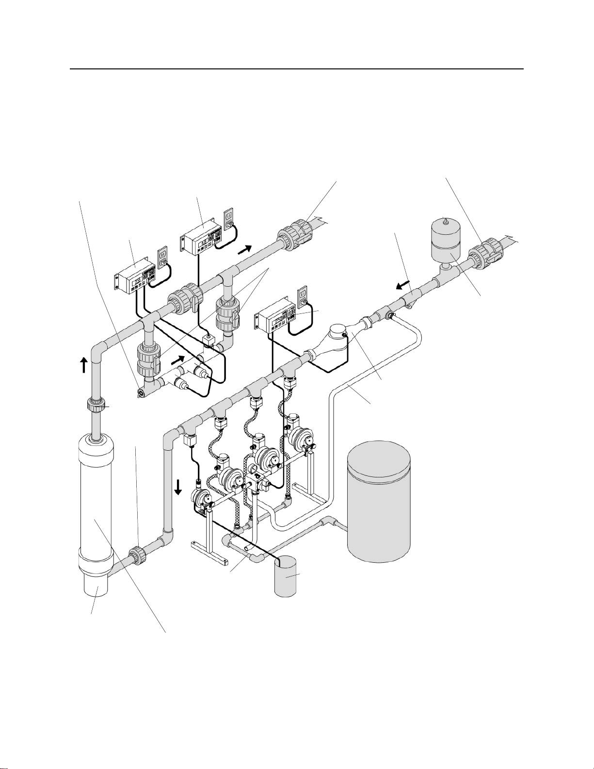
Primary Requirements for Proper
Operation
There are some conditions which must be met in
order for your injection system to operate properly.
These are given here:
●Minimum line pressure of 30 psig,
measured on the downstream side of the
injector. If you do not have a pressure
reading of 30 pounds at the pressure
gauge on top of the unit, then you do not
have enough pressure. If the water is
flowing out to an open tank or onto the
ground, there will probably not be
sufficient back pressure to meet the 30
psig requirement even if there is much
greater pressure (e.g. 50 psig) on the
inlet. This is the most common cause of
erratic operation. In this situation you
should install a valve and pressure gauge
downstream from the unit. Close the valve
until the gauge reads 30 psi or greater.
●The flow rate should be within the range
of your flow meter. (See Table 1 in your
meter manual for flow range information)
●The manifold discharge line and any
tubing attached must open to “daylight”
and go directly to a drain. Do not obstruct
or elevate the line at any point. If a long
line is needed, it should be expanded to a
larger size. Put an air vent or gap
between the primary and the extended
line.
●Too much chemical feed is not caused by
a mechanical malfunction. It is probably
due to siphoning or gravity flow of
chemical through the feeder during
periods of zero pressure on the system.
The system shutoff valve should be
downstream of the system to maintain
pressure at all times.
Do not store chemicals in tanks
where the level will be more than
just a few feet above the
discharge point of the pumpers.
If you have very large solution
storage tanks you should use them to fill
smaller “day tanks”. This will eliminate the
chance of large quantities of chemicals
draining into your watering system.
H.E. Anderson Co. 8IGHC-11-10