H2O Innovation 200 User manual

H2O Innovation 819-344-2288 usine@h2oinnovation.com
H2O CONCENTRATOR
Models 200 & 300

2
TABLE OF CONTENT
I. Introduction p.3
II. Safety and Equipment Set-up p.3
III. Importance of Membrane Rinsing and Washing p.4
IV. Membrane installation p.5
V. Plumbing p.7
VI. 5 Micron Pre-Filter Installation p.8
VII. Equipment Accessories p.8
VIII. Operating the Concentrator p.9
A. Start-up and Initial Rinse Cycle p.9
B. Maple Sap Concentration Process Cycle
General sap water removal operation p.10
C. 3 Hour Rinse Cycle p.10
D. End of Day Cleaning and Final Rinse Cycle p.11
E. Equipment Storage (end of season) p.11
F. Troubleshooting p.12
G. Warranty p.12
INDEX p.13
1. Flow rate calculation and records p.13
2. Maintenance and Operation Logbook table p.14
3. Equipment circuit diagram
Same for both 200 & 300 model p.19

3
I. INTRODUCTION
This manual is written to provide set-up and operational information for the Concentrator
series by H2O Innovation, including both the 200 and 300 models.
The only difference between the two models is that the 200 has two membranes and the
300 has three. All of the information below applies to both models.
II. SAFETY AND EQUIPMENT SET-UP
The Concentrator equipment has been designed and manufactured to operate safely in
an appropriate setting with specific electrical sources, plumbing, tanks and other
accessories.
The concentrator system must be operated on a flat and level surface with ample space
around it for operation as well as maintenance. Space for plumbing and fluid redirection
must be allocated for easy access. Fluid valves can be designed and used to simplify
operations. A separate electrical service line must include a fault switch and be located
appropriately to avoid a cord tripping hazard.
The membrane container fastening clamps and rubber gaskets also referred to as U-
cups must be assembled as described in this manual to insure there will be no leaks or
pressure failures. The cap fasteners on the containers must be checked periodically to
insure that they remain tight.
CAUTION: High voltage equipment (220 volts) in potentially wet conditions presents the
possibility of electrocution. Also, the high pressure membrane containers sealed with
mechanical clamps and rubber gaskets and operating at pressures up to 275 PSIG are
cause for concern as mistakes in assembly or loosening can cause catastrophic failure
and personal harm.
Note 1: The Concentrator is equipped with a three prong electrical plug which does not
fit all standard 220 volt outlets. Please check your local electrical supply house for the
proper outlet or replace the plug.
Note 2: The possibility of electric shock is exacerbated by potential permeate or
concentrate leakage. The membrane container rubber seals and mechanical fasteners
must be properly assembled, tightened and checked regularly to insure that safe
operating conditions prevail throughout the operating process, as a pressure failure in
any of the vessels could cause personal injury.

4
III. Importance of Membrane Rinsing and Washing
The membrane is a key system component that enables the removal of water from sap
and is an expensive item to replace. Its spiral-type structure and its surface made of very
fine pores make cleaning difficult but most important. Neglecting adequate maintenance
will allow the accumulation of bacteria that will obstruct the membrane and may cause
permanent damage. Meticulous maintenance will protect the investment and insure
quality production for many years. The Concentrator is a very reliable and efficient
system that will provide quality and low-cost production provided it is regularly and
adequately maintained. The membrane performance and life expectancy can be
compromised by exposure to impurities such as iron and other minerals, so any rinsing
or flushing must be done with known mineral-free water or sap permeate to insure
longevity. Proper maintenance and daily rinsing will improve the life of the membrane;
however, performance will slowly degrade over time with normal use.
The membrane performance can be monitored by measuring and recording the flow
rates periodically (on a daily or weekly basis). It is important to account for a
temperature correction factor when measuring the flow rate performance as described in
the appendix. When appropriate, the membrane can be returned to the manufacturer for
an industrial cleaning. This will help extend the life of the membrane. The rinse and
wash cycles included in the operational process described in the following sections (A
through D) as well as storage in section E are very important to a long life and must be
performed along with flow rate performance measurements with documented records for
proof of adherence to validate any warranty.
Reference: A training presentation on the subject of membrane technology is posted in
the H2O Innovation web site at http://maple.h2oinnovation.com/en/training
Note: The Concentrator warranty will not be valid unless proof of maintenance
according to specifications is done and documented. The maintenance and operation
logbook accurately and regularly filled out will be that requested proof. The logbook
format is shown in the index.

5
IV. MEMBRANE INSTALLATION
Note: The membrane must be soaked in distilled water in a membrane storage vessel for
24 hours prior to installation. The membrane’s performance will be permanently altered if
this is not done.
Remove the clamps and black caps at the end of the membrane containers. The caps
pull straight out once the clamps are removed. Insert the membranes into the membrane
containers insuring that the arrows imprinted on the membrane and membrane container
point in the same direction. See the photos below.
Note: Arrows point in the same direction

6
Next, install the black rubber o-ring referred to as the U-cup into the groove at the end of
the membrane. The U-shape of the ring must be facing out from the container.
Lubricate the U-cup and cap o-ring with a food grade glycerin based lubricant. Firmly
push the membrane into the container with a twisting action to insure proper seating.
Installed U-cup
Re-install the membrane container black caps and housing clamps.
Re-installed black
caps and housing clamps
This completes the installation of the membranes.

7
V. PLUMBING
This figure shows a typical set up of the Concentrator plumbing with washing and holding
tanks and appropriate valves.
Permeate line
Concentrate line
Permeate line

8
VI. 5 MICRON PRE-FILTER CARTRIDGE INSTALLATION
Unscrew the pre-filter housing, pull it down, insert a Purtex 5 micron filter cartridge
(P/N Purpx05-9-7/8) and reassemble the housing. The pre-filter cartridge must be
replaced at the beginning of each season and when the pressure differential exceeds 20
psi.
Pre-filter housing F1
VII. Equipment Accessories
Accessories used during operation
- Bio-membrane cleaner, P/N CHE-BIOMEMB1G
- Purtex 5 micron filter cartridge, P/N Purpx05-9-7/8
- U cup 4" (membrane rubber gasket), P/N UCUP904
- Food grade glycerin based lubrication for U cup
- Permeate and concentrate storage tanks
Accessories used for seasonal storage
- Membrane storage container (PVC sleeve),
P/N SPH-UNI-00-16A Storage vessel 4"
- Storage Solution, P/N CHE-REMISACE-1G

9
OPERATING THE CONCENTRATOR
A. Start-Up and Initial Rinse Cycle
The purpose of the start-up and initial rinse cycle is to provide a one-time flush for newly
installed membranes using mineral free or permeate water. This initial rinse cycle is
necessary to eliminate any residue left over from the manufacturing process in the
membranes. Note that any minerals in tap water such as iron can contaminate or clog
the membrane and should not be used for this rinse cycle. The initial rinse cycle can be
accomplished using permeate fluid by redirecting the plumbing lines to direct permeate
fluid back into the Concentrator. Under these conditions the fluids exiting the
concentrator will be waste fluids. It is important that the Concentrator equipment
including the pumps is warm enough to insure that the sap and concentrate inside it
doesn’t freeze.
The start-up and initial rinse cycle is accomplished by following the next 7 steps.
1. Install the new pre-filter in filter housing F1.
2. Back off the CV concentrate valve 2 turns prior to starting the Concentrator.
3. Close the valve in the sap feed line to the Concentrator.
4. Open the valve in the permeate line to the Concentrator.
5. Place the concentrate and permeate lines to the drain.
6. Start the Concentrator and adjust the pressure in pressure gauge M2, after the pre-filter,
to 100 PSI. Then adjust the pressure down to a minimum of 60 PSI using the CV
concentrate valve.
7. Continue rinsing the membranes for 15 minutes or with 50 to 100 gallons of permeate or
mineral free water.
Pressure gauges
M1 & M2
ON/OFF switch
Concentrate &
permeate flow meters
Concentrate
sampling valve
Temperature
gauge
Pre-filter housing F1
CV Concentrate
valve
Permeate sampling
valve

10
B.Maple Sap Concentration Process Cycle
(General sap water removal operation)
The purpose of maple sap concentration cycle is to remove water from the sap.
The maple sap concentration cycle is accomplished by following the next 7 steps.
1. Back off the concentrate control valve 2 turns prior to starting the Concentrator.
2. Open the valve in the sap feed line to the Concentrator.
3. Close the valve in the permeate line to the Concentrator.
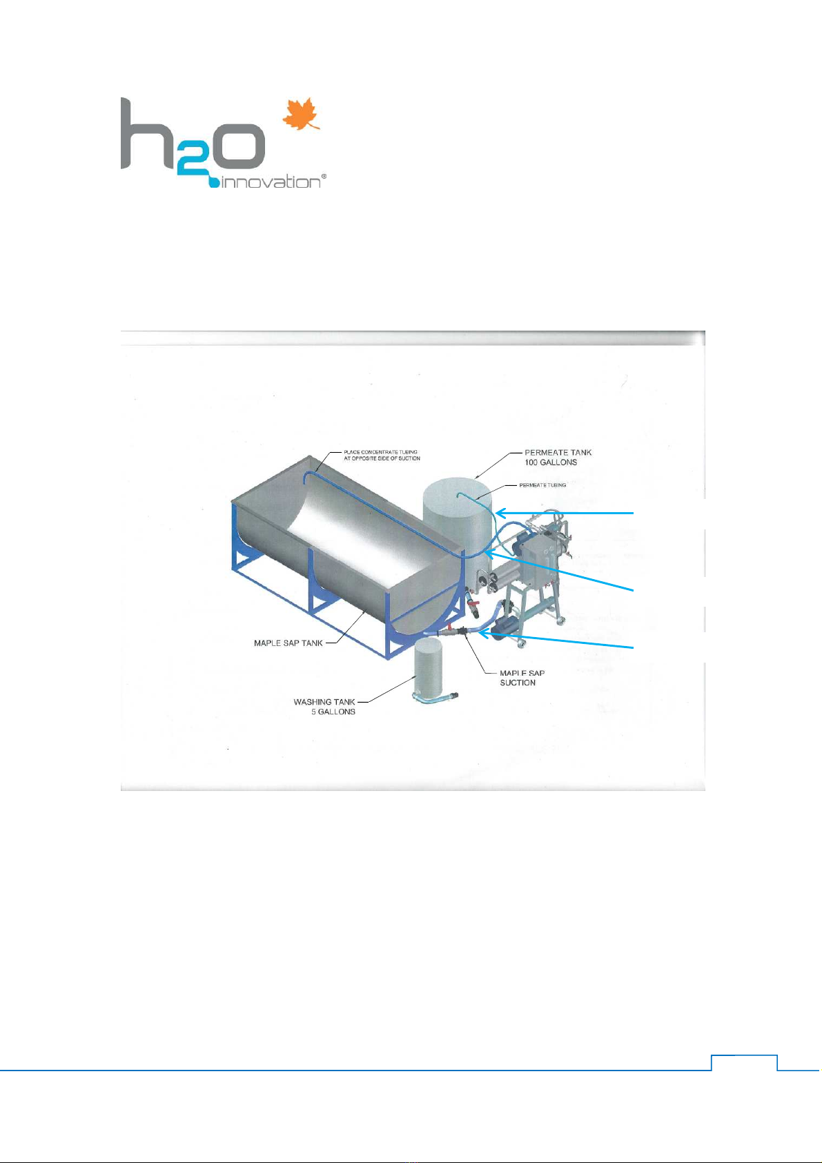
4. Place the concentrate and permeate lines to their respective storage tanks.
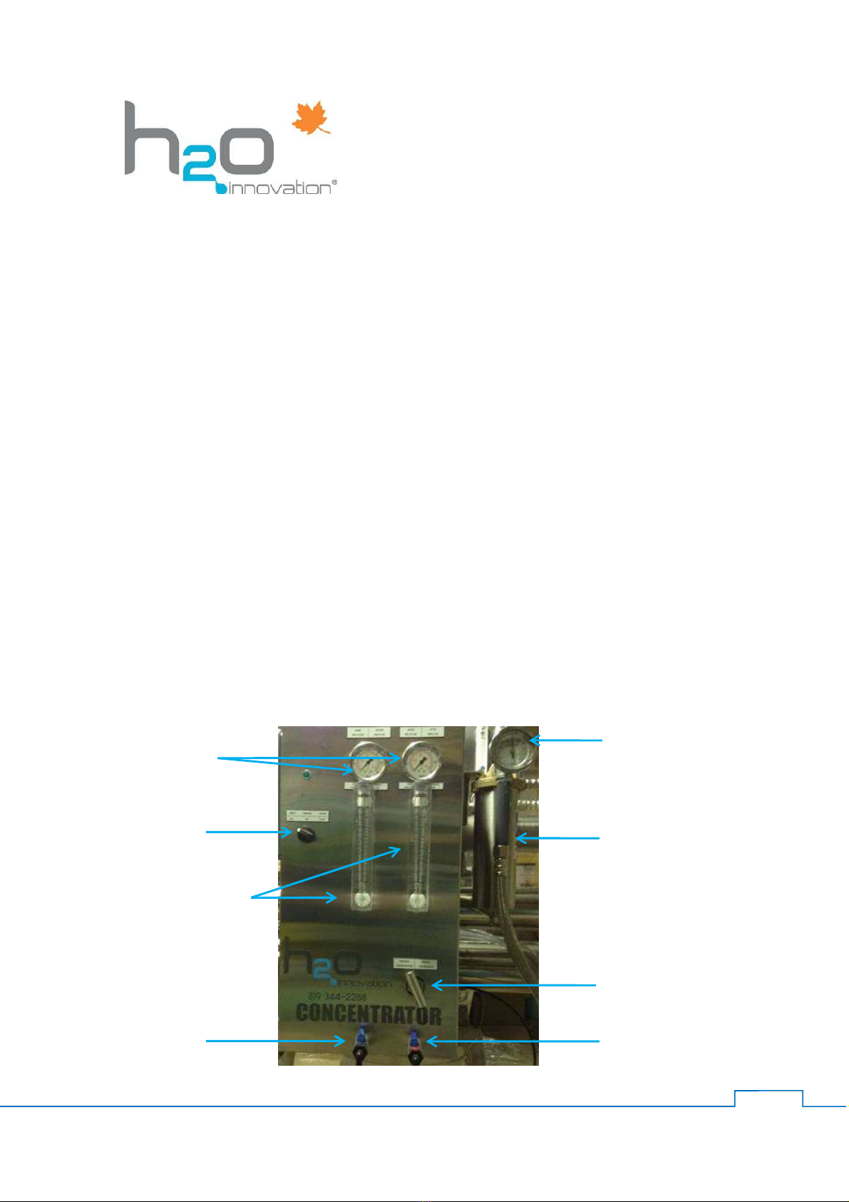
5. Start the Concentrator and adjust the CV concentrate valve in such that the flow meters
for the permeate fluid and concentrate fluid flow rates are both 50%.
6. Take a sample of fluid from the concentration sample valve and check the sugar
concentration using a refractometer or hydrometer, after 15 minutes of operation. The
concentration should have doubled.
Note: It is good practice to occasionally check the permeate fluid for sugar content to
insure the Concentrator is working properly.
7. Continue concentrating the sap for 3 hours until the next scheduled rinse cycle.
C. 3 Hour Rinse Cycle
The 3 hour rinse cycle is necessary after every 3-hour increment of continuous
concentration operation. The purpose of the process is to rinse/flush the membranes
using permeate or mineral free water by redirecting the flow of rinsing water into the
Concentrator. Under these conditions the fluid exiting the Concentrator will be waste.
The 3 hour rinse cycle can be accomplished by following the next 6 steps.
1. Back off the concentrate control valve 2 turns prior to starting the Concentrator.
2. Close the valve in the sap feed line to the Concentrator.
3. Open the valve in the permeate line to the Concentrator.
4. Place the concentrate and permeate lines to the drain.
Note: Roughly, the first three minutes of the rinse will contain about 15 gallons of
concentrated sap which can be saved prior to moving the concentrate line to the drain in
step 4. A refractometer or hydrometer can be used to monitor the sugar content by
sampling at the concentrate flow meter.
5. Start the Concentrator and adjust the pressure in pressure gauge M2, after the pre-filter,
to 100 PSI. Then adjust the pressure down to a minimum of 60 PSI using the CV
concentrate valve.
6. Continue rinsing the membranes with 50 to 100 gallons of permeate water.

11
D. End of Day Cleaning and Final Rinse Cycle
The purpose of this process cycle is to clean the Concentrator prior to shutting down at
the end of the day.
Note: Save approximately 200 to 400 gallons of permeate for the end of the season
cleaning described below under section E. Equipment Storage (end of season).
E. Equipment Storage (end of season)
It is very important to thoroughly wash the equipment and membrane at the end of the
maple season before storing the equipment over the summer and fall. Additionally, the
manufacturer strongly recommends a deep wash for the membrane by sending it to H2O
Innovation. Alternatively, the following 11-step do-it-yourself cleaning process must be
done.
11-step do-it-yourself equipment and membrane cleaning process steps.
1. One rinse cycle - thoroughly rinse the system with permeate or distilled water
2. Follow with a wash cycle - use Bio-Membrane Cleaner (P/N CHE-BIOMEMB1G)
3. Do another rinse cycle
Safety note: Set the electrical breaker in the main power line to the off position in the
main power line to insure the system is not accidentally started during the next 8 steps.
4. Empty the membrane housing by removing the end caps.
5. Drain the pressure and recirculation pumps by relieving the drain valves
6. Empty all pipes and dispose of the 5 micron filter
7. Fill a membrane PVC sleeve (P/N SPH-UNI-00-16A Storage vessel 4") with 1 liter of
storage solution (P/N CHE-REMISACE-1G) mixed with 1 gallon of distilled water of
permeate
8. Remove membrane from concentrator and slowly insert into the PVC sleeve
9. Top off the sleeve with distilled water or permeate once the membrane is installed
10. The membrane will absorb some of the solution causing the liquid level to go down. After
3 or 4 minutes, complete filling with distilled water or permeate.
11. Install cap on the PVC sleeve and store in a cool (~7 0C, 45 0F) place.
The following 4 precautions specified by the manufacturer are necessary to safely store
the membrane over the off-season.
1. The membrane must never be exposed to freezing temperatures. This condition will void
the warranty.
2. The membrane must be kept in a cool place (~7 0C or 45 / 0F)
3. The membrane must be kept moist at all times. The manufacturer specifies that it should
be kept immersed in a PVC sleeve or tank.
4. The membrane must remain soaking in a storage solution (P/N CHE-REMISACE-1G) to
prevent bacteria from spreading.

12
F. Troubleshooting
Many problems can easily be solved prior to calling for help. This section provides a list
of typical problems that occur and solutions saving time and money. If the problem
persists, contact the H2O Innovation customer service department and a technician will
provide support.
Problems Possible Causes Solutions
1. System will not start 1.1 Breakers are not reset
1.2 The Concentrator is not
plugged in
1.1.1 Check electrical main and
systems breakers
1.2.1 Plug in the Concentrator
2. Concentrator won’t stay running
when power switch recoils 2.1 Suction screen plugged
2.2 5-micron filter clogged
2.3 Sap or permeate volume
exhausted
2.4 Pressure out of spec
2.2.1 Clean suction screen
2.2.2 Change 5-micron filter
2.2.3 Replenish sap or permeate
2.2.4 Check pressure switch for 50
PSI
3. System won’t sustain pressure 3.1 Suction screen plugged
3.2 Concentrate control valve not
adjusted properly
3.1.1 Clean suction screen
3.2.1 Adjust concentrate control
valve
4. Concentrate and/or permeate
leaking from Concentrator 4.1 Membrane container cap
leaking 4.1.1 Check and tighten end
clamps
4.1.1.1 Put food grade grease on
end cap o-rings
5. Concentrate percentage too low 5.1 Membrane passing sugar 5.1.1 Check U-Cup for proper
installation
5.1.1.1 Remove membrane from
container and check U-Cup for
damage
G. Warranty
All components of new Concentrators are guaranteed for one year from date of purchase
for parts and labor against any workmanship defect.
The warranty does not cover scaling or clogging of the membrane.
The membrane 2-year warranty will be honored only if it allows more sugar than normal to
go through according to specifications.
The warranty will be valid if operation and maintenance of the system is carried out as
directed in this manual and a logbook is kept up-to-date with all technical data recorded
as required.
H2O Innovation will not be liable for any personal prejudice, any loss of production and
any direct or indirect damage that could result from malfunction or misuse of this
equipment.

13
INDEX
1. Flow rate calculation and records
Temperature Correction Factor Chart
P.E.P. Cold Water: Reference temperature is 13°C
Temperature
0
C /
0
F
Correction
factor Temperature
0
C /
0
F
Correction
factor
0 / 32 0.672 13 / 55 1.000
1 / 34 0.695 14 / 57 1.028
2 / 36 0.719 15 / 59 1.055
3 / 37 0.742 16 / 61 1.084
4 / 39 0.766 17 / 63 1.112
5 / 41 0.790 18 / 64 1.142
6 / 43 0.816 19 / 66 1.170
7 / 45 0.842 20 / 68 1.200
8 / 46 0.866 21 / 70 1.229
9 / 48 0.893 22 / 72 1.259
10/ 50 0.919 23 / 73 1.289
11 /52 0.946 24 / 75 1.319
12 / 54 0.973 25 / 77 1.350
Calculation example:
Flow variation compared with temperature. If the permeate flow rate is 6 GPM as measured on
the permeate flow meter at 20 0C as measured on the thermometer then the corrected flow rate at
13 0C will be 6 GPM + 1.200 = 5 GPM

14
2. Maintenance and Operation Logbook table
Sugar Level Flow-Meters PWP Pressure Gauges
1 2 3 4 5 6 7 8 9 10
Date Operating
hours
Operation
temperature
0C / 0F
Maple Sap
0Brix Concentrate
0Brix
Concentrate
Flow
GPM
Permeate
Flow
GPM
Corrected
@ 13 0CPressure @
membrane Pressure @
pre-filter

15
2. Maintenance and Operation Logbook table
Sugar Level Flow-Meters PWP Pressure Gauges
1 2 3 4 5 6 7 8 9 10
Date Operating
hours
Operation
temperature
0C / 0F
Maple Sap
0Brix Concentrate
0Brix
Concentrate
Flow
GPM
Permeate
Flow
GPM
Corrected
@ 13 0CPressure @
membrane Pressure @
pre-filter

16
2. Maintenance and Operation Logbook table
Sugar Level Flow-Meters PWP Pressure Gauges
1 2 3 4 5 6 7 8 9 10
Date Operating
hours
Operation
temperature
0C / 0F
Maple Sap
0Brix Concentrate
0Brix
Concentrate
Flow
GPM
Permeate
Flow
GPM
Corrected
@ 13 0CPressure @
membrane Pressure @
pre-filter

17
2. Maintenance and Operation Logbook table
Sugar Level Flow-Meters PWP Pressure Gauges
1 2 3 4 5 6 7 8 9 10
Date Operating
hours
Operation
temperature
0C / 0F
Maple Sap
0Brix Concentrate
0Brix
Concentrate
Flow
GPM
Permeate
Flow
GPM
Corrected
@ 13 0CPressure @
membrane Pressure @
pre-filter

18
2. Maintenance and Operation Logbook table
Sugar Level Flow-Meters PWP Pressure Gauges
1 2 3 4 5 6 7 8 9 10
Date Operating
hours
Operation
temperature
0C / 0F
Maple Sap
0Brix Concentrate
0Brix
Concentrate
Flow
GPM
Permeate
Flow
GPM
Corrected
@ 13 0CPressure @
membrane Pressure @
pre-filter

19
3. Equipment circuit diagram (same for both 200 & 300 model)
This manual suits for next models
1
Table of contents