H3C S7502 User manual

Installation Manual
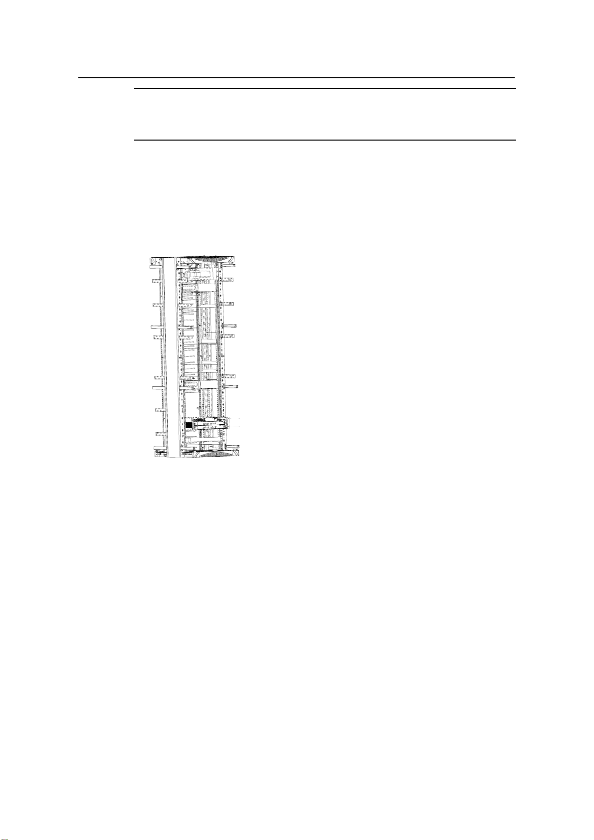
H3C S7502 Ethernet Switch Table of Contents
i
Table of Contents
Chapter 4 Hardware Installation ..................................................................................................4-1
4.1 Confirming the Installation Preparations............................................................................4-1
4.2 Installation Flowchart.........................................................................................................4-1
4.3 Mounting the Switch to the Designated Position...............................................................4-2
4.3.1 Mounting the Switch onto a 19” Standard Rack......................................................4-2
4.3.2 Mounting the Switch on the Tabletop......................................................................4-3
4.4 Installing Modules of the Switch ........................................................................................4-3
4.5 Connecting the Grounding Cable and Power Cables........................................................4-3
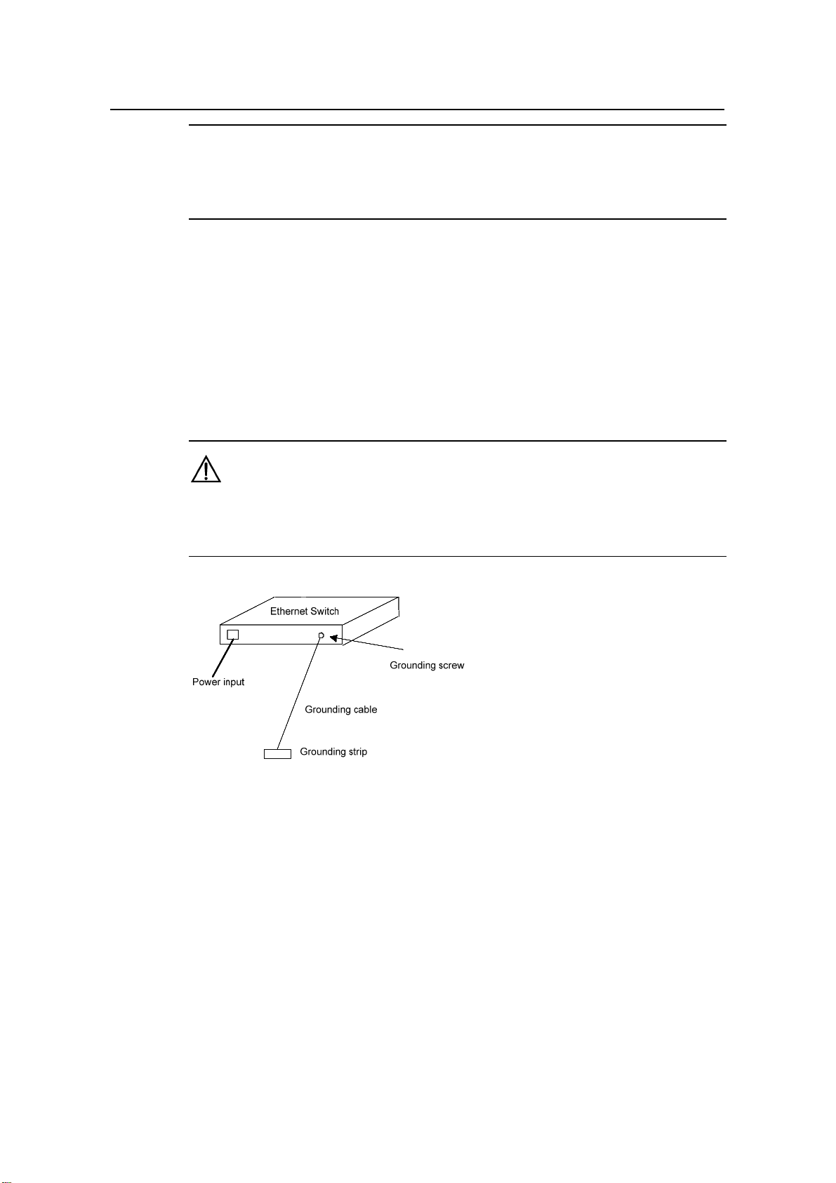
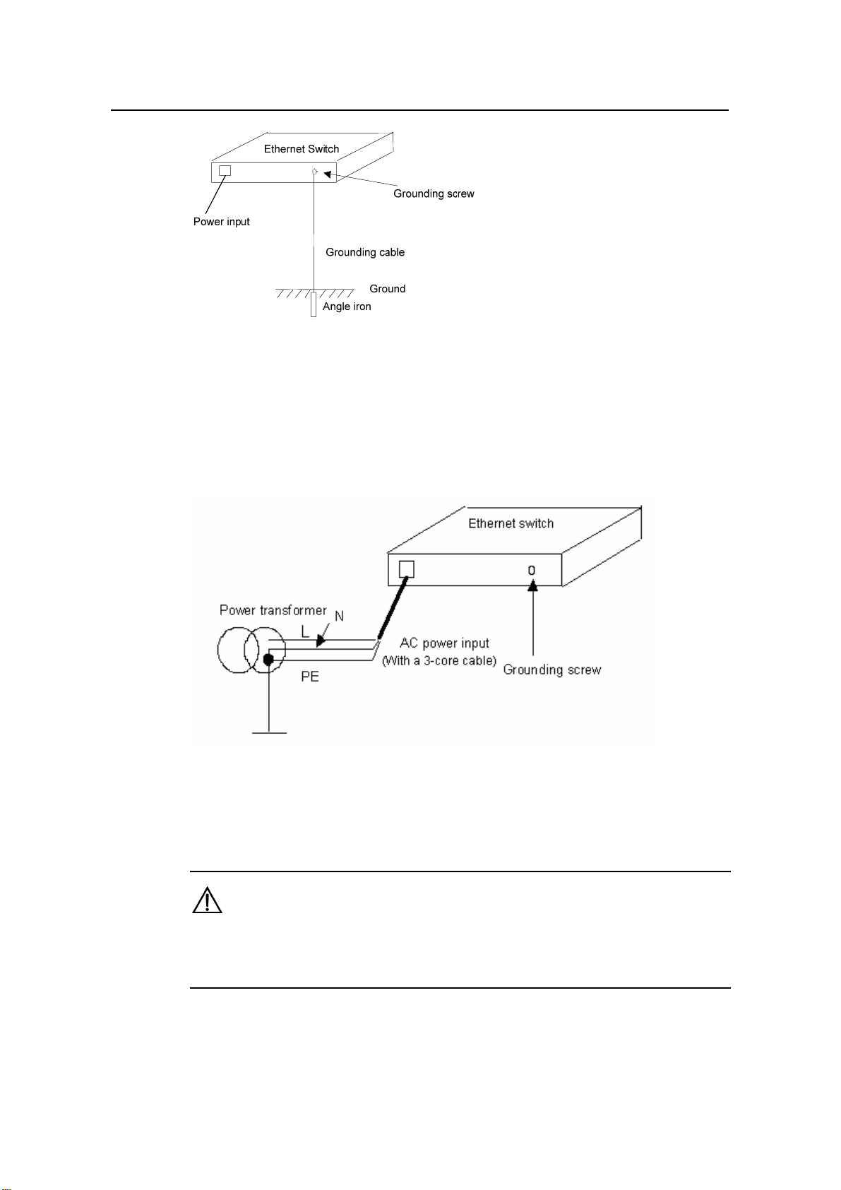
4.5.1 Connecting the Grounding Cable............................................................................4-3
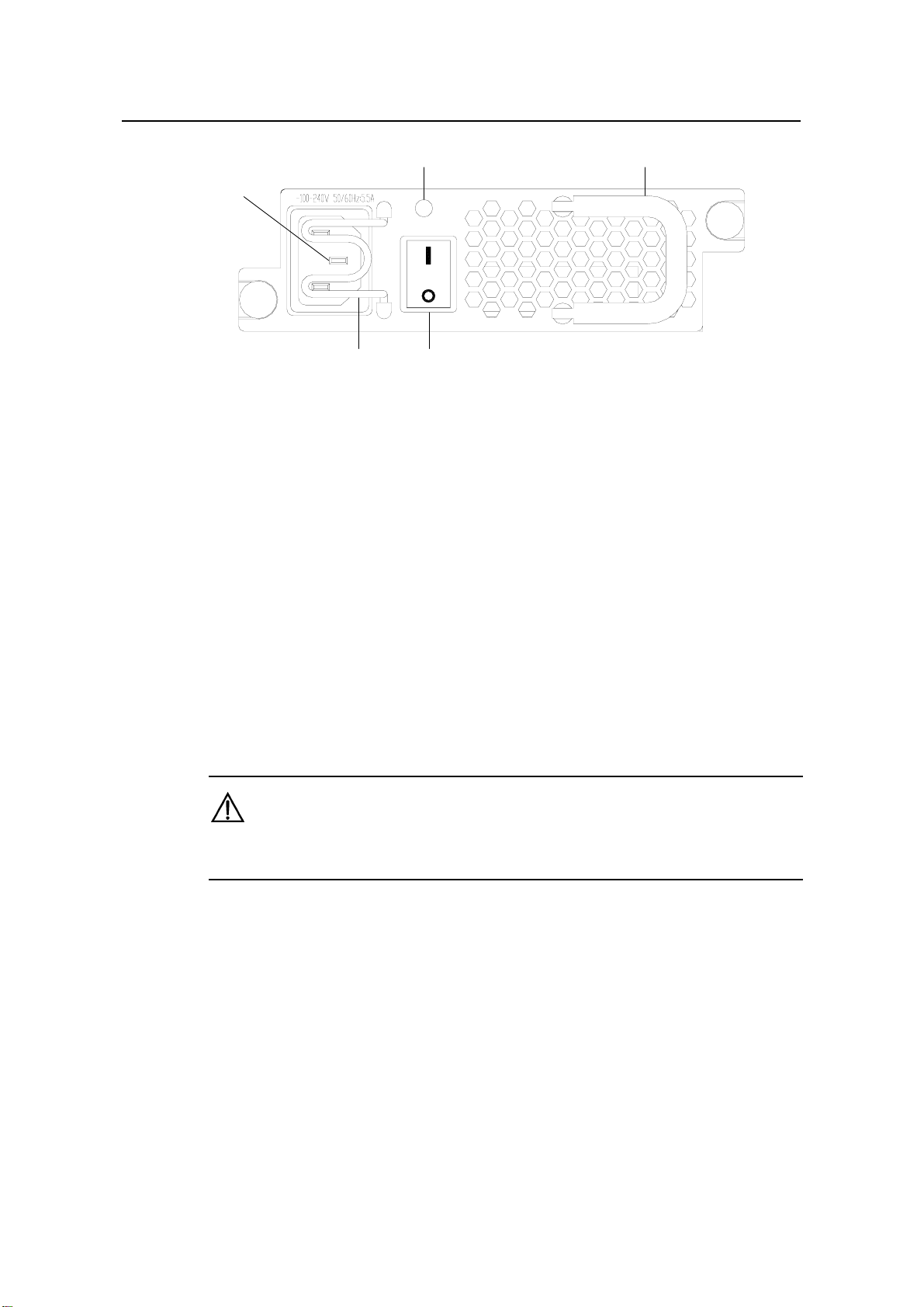
4.5.2 Connecting the AC Power Cable ............................................................................4-5
4.5.3 Connecting the DC Power Cable............................................................................4-6
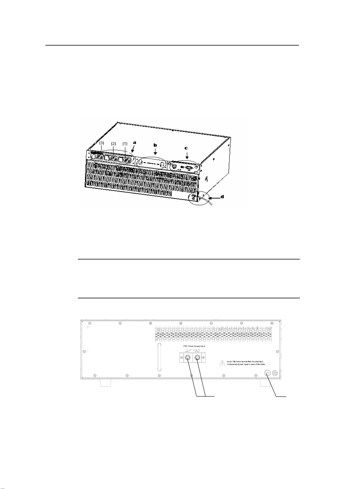
4.5.4 Connecting the PoE Power Cable...........................................................................4-8
4.6 Connecting Interface Cables .............................................................................................4-9
4.6.1 Connecting the Console Cable ...............................................................................4-9
4.6.2 Connecting the COM Port Cables.........................................................................4-10
4.6.3 Connecting Category-5 Cables.............................................................................4-11
4.6.4 Connecting Fibers.................................................................................................4-12
4.7 Cabling.............................................................................................................................4-14
4.7.1 Table-Mounted Switch ..........................................................................................4-14
4.7.2 Rack-Mounted Switch...........................................................................................4-14
4.8 Cable Binding...................................................................................................................4-14
4.8.1 Use of Labels ........................................................................................................4-14
4.8.2 Precautions for Cable Binding...............................................................................4-14
4.9 Checking the Installation..................................................................................................4-18

Installation Manual
H3C S7502 Ethernet Switch Chapter 4 Hardware Installation
4-1
Chapter 4 Hardware Installation
The S7502 is designed for indoor application and must be fixed when applied.
4.1 Confirming the Installation Preparations
zMake sure that you have read Chapter 3 carefully.
zAll requirements introduced in Chapter 3 have been met.
4.2 Installation Flowchart
Figure 4-1 Installation flowchart of the switch

Installation Manual
H3C S7502 Ethernet Switch Chapter 4 Hardware Installation
4-2
Note:
The switch should be equipped with at least two sets of power supply.
4.3 Mounting the Switch to the Designated Position
4.3.1 Mounting the Switch onto a 19” Standard Rack
The S7502 has an integrated chassis and should operate indoors.
Figure 4-2 Mount an S7502 Ethernet switch onto a 19” standard rack
Take the following installation steps.
Step 1: Confirm the following before installation:
zThe rack has been well fixed. The installation position for the switch has been well
arranged and there is no obstacle around.
zThe switch is ready for installation and has been carried to a place near the rack
and convenient for moving.
Step 2: Install the wiring channel and mounting angle sets shipped with the switch.
Step 3: With two people lifting the switch at both sides slowly, move the switch to a
place in front of the rack.
Step 4: Carry the switch a little higher than the rack tray or guides. Put the switch on the
tray or the guides and push it into the rack.
Step 5: Fasten the angle sets on the 19-inch columns to seat the switch in the chassis.

Installation Manual
H3C S7502 Ethernet Switch Chapter 4 Hardware Installation
4-3
4.3.2 Mounting the Switch on the Tabletop
Step 1: Confirm the following before installation:
zThe table is firm enough to hold the switch and cables.
zNo obstacles around the table that may interfere with the installation.
zThe switch is ready for installation and has been carried to a place near the
cabinet and convenient for moving.
Step 2: With two people lifting the switch at both sides slowly, position the switch to a
place in front of the table.
Step 3: Carry the switch a little higher than the table and put the switch on it.
4.4 Installing Modules of the Switch
Common modules of the switch include the cards, power module, and fan frame. For
detailed installation procedures, see Chapter 6 “Hardware Maintenance”.
4.5 Connecting the Grounding Cable and Power Cables
4.5.1 Connecting the Grounding Cable
Caution:
For the safety of personnel and equipments, the switch must be well grounded. The
resistance between switch chassis and the ground should be less than 1 ohm.
Note:
The grounding screw is located on the bottom right corner of the chassis.
I. Common grounding environment
Step 1: Remove the screw from the grounding hole in the switch chassis.
Step 2: Set the grounding cable connector shipped with the switch around the
grounding screw.
Step 3: Fasten the grounding screw in the grounding hole on the chassis.
Step 4: Connect the other end of the grounding cable to the grounding strip of the
switch.

Installation Manual
H3C S7502 Ethernet Switch Chapter 4 Hardware Installation
4-4
Note:
Each cabinet has a grounding strip, to which you can connect the grounding cable of a
switch.
II. Other grounding environment
Hereafter introduced some methods for grounding the switch in different environment.
zIf there is a grounding strip in the Ethernet switch installation environment, attach
one end of the yellow-green protection grounding cable to the grounding screw of
the grounding strip and fasten the captive nuts. The grounding cable of a switch
shall be connected to the project ground of the equipment room.
Caution:
Note that the fire main and lightning rod of a building are not suitable for grounding the
switch.
Figure 4-3 Connect the grounding cable to the grounding strip
zIf there is no grounding strip but earth nearby and the grounding body is allowed to
be buried, you can simply hammer an angle iron or steel pipe no shorter than 0.5m
into the earth. In this case, the yellow-green protection grounding cable should be
welded with the angle iron (steel pipe) and the joint should be processed against
eroding.

Installation Manual
H3C S7502 Ethernet Switch Chapter 4 Hardware Installation
4-5
Figure 4-4 Connect the grounding cable to the grounding body nearby
zIf there is no grounding strip and no grounding body can be buried, and the
Ethernet switch is AC powered, you can grounded through the PE wire of the AC
power supply. In this case, make sure that the PE wire of the AC power supply has
been well grounded at the power distribution room or AC power supply
transformer side.
Figure 4-5 Connect the grounding cable through AC PE wire
4.5.2 Connecting the AC Power Cable
Caution:
For lightning protection, the AC power should be led through the external lightning
device into the S7502.

Installation Manual
H3C S7502 Ethernet Switch Chapter 4 Hardware Installation
4-6
(1)
(2) (3)
(4)(5)
(1) AC input socket (2) Power LED
(3) Handle of power module (4) Power switch
(5) Bail latch
Figure 4-6 S7502 power module
The power module has AC input socket with bail latch and a power LED on its front
panel (The LED is described in 6.1.2).
Step 1: Pull up the bail latch to the right. The bail latch is on the left side of the panel.
Step 2: Insert the AC power cable which is shipped with the switch into the AC input
socket of the power supply module.
Step 3: Push back the bail latch to keep the power cable from being removed.
Step 4: Insert the other end of the power cable into the site power socket.
4.5.3 Connecting the DC Power Cable
Caution:
Power off all the related parts of the switch before connecting DC power cable.

Installation Manual
H3C S7502 Ethernet Switch Chapter 4 Hardware Installation
4-7
PGNDRTN -48V
-48V 60V;15A
(1) (2) (3)
(4)
(1) Power switch (2) Power LED
(3) Handle of power module (4) DC power socket
RTN: -48 V working ground -48V: -48 V DC power
PGND: protection ground (You do not need to connect it because it is connected to the
chassis from inside the power module).
Figure 4-7 S7502 DC power module
Follow these steps to connect the DC power cable:
Step 1: Install the DC power plug components.
Dustproof cover
Cable tie
Connector Screw 4 Cable 2
Screw 1 Screw 2
Screw 3 Cable 1 Dustproof cover
Cable tie
Connector Screw 4 Cable 2
Screw 1 Screw 2
Screw 3 Cable 1
Figure 4-8 DC power plug
As shown in Figure 4-8, first insert two cables into the appropriate holes through
dust-proof shield, and then fix the cables separately by using screws 1 and 2. Make
sure that the positive and negative ends of the cable are inserted appropriately in
accordance with the silkscreen print on the holes.
Fix the dust-proof shield by screws 3 and 4 by using a small flathead screwdriver, see
Figure 4-8.
Enlace the two cables to the polarizing key at the back of the dust-proof shield using the
cable tie, as shown in Figure 4-8.
Step 2: After installing connector component, directly insert the component into DC
socket on the cabinet (Note that the component cannot be inserted in the wrong

Installation Manual
H3C S7502 Ethernet Switch Chapter 4 Hardware Installation
4-8
direction), and then fix the screws 1 and 2 carried by the connector itself to the
appropriate holes on the cabinet socket using a small flathead screwdriver.
Step 3: Check whether the power LED is ON. If the LED is ON, it indicates the power
cable is properly connected.
4.5.4 Connecting the PoE Power Cable
(a) AC power input socket (b) DC power output
(c) RS232 and RS485 interfaces (d) Chassis grounding point
Figure 4-9 Appearance of the PSE
Note:
For the method of installing the PSE2500-A3, see the related manual shipped with the
switch.
(1)(2)(3)
(1) Grounding screw (2) RTN(+) terminal of of PoE power supply
input
(3) NEG(-) terminal of PoE power supply input
Figure 4-10 Rear view of an S7502 PoE chassis

Installation Manual
H3C S7502 Ethernet Switch Chapter 4 Hardware Installation
4-9
Follow these steps to connect the PoE power cable:
Step 1: Loosen the mounting screw of the PoE terminal block on the rear panel of the
switch.
Step 2: Insert the -48V OT terminal of the DC power cable to the NEG (-) terminal of the
switch and fasten the mounting screw; insert the other end to the NEG (-) terminal of
the external PoE power supply.
Figure 4-11 Rear panel of external PoE power supply (PSE2500-A3)
Step 3: Insert the GND OT terminal of the DC power cable to the RTN(+) terminal of the
switch and fasten the mounting screw; insert the other end to the RTN(+) terminal on
the rear panel of the external PoE power supply.
Step 4: Insert the PGND OT terminal of the DC power cable to the grounding screw of
the switch and fasten the mounting screw; insert the other end to the grounding bar for
the switch.
4.6 Connecting Interface Cables
4.6.1 Connecting the Console Cable
I. Introduction
Console cable is an 8-core shielded cable. One end of the cable is a crimped RJ-45
connector, which is to be plugged into the Console port of the switch. The other end is
furnished with a DB-9 (male) connector and can be inserted to the 9-core (female)
socket. The following figure illustrates the Console cable.
Figure 4-12 A Console cable

Installation Manual
H3C S7502 Ethernet Switch Chapter 4 Hardware Installation
4-10
Table 4-1 Console cable pinout
RJ45 Signal DB-9 Signal
1 RTS 8 CTS
2 DTR 6 DSR
3 TXD 2 RXD
4 SG 5 SG
5 SG 5 SG
6 RXD 3 TXD
7 DSR 4 DTR
8 CTS 7 RTS
II. Connect a Console cable
Take the following steps to connect the Console cable when configuring the switch via a
terminal.
Step 1: Plug the DB-9 female plug of the Console cable to the serial port of a PC or a
terminal where the switch is to be configured.
Step 2: Connect the RJ-45 connector of the Console cable to the Console port of the
switch.
Note:
The RS-232 serial port is not hot swappable. You are recommended to disconnect the
power supply to the PC or terminal before connecting the DB-9 connector. Or you can
first connect the DB-9 connector and then insert the RJ-45 connector of the console
cable into the console port.
4.6.2 Connecting the COM Port Cables
I. Introduction
COM port cable is an 8-core shielded cable. One end of the cable is crimped with an
RJ-45 connector, for connection with the COM port of the switch; the other end is
attached with a DB-9 female connector and can be inserted to 9-pin male connector.
The COM port cable is the same as the Console cable.
For detailed description, see Figure 4-12 and Table 4-1.

Installation Manual
H3C S7502 Ethernet Switch Chapter 4 Hardware Installation
4-11
II. Connect COM Port Cable
When connected to the external PoE power supply, the switch can monitor the running
state of the external PoE power supply through the COM port. Take the following steps
to connect the COM port cable:
Step 1: Insert the DB-9 female plug of the COM port cable to the RS232 port of the PoE
power supply.
Step 2: Connect the RJ-45 connector of the COM port cable to the COM port of the
switch.
4.6.3 Connecting Category-5 Cables
I. Introduction
The 10Base-T/100Base-TX and 1000Base-T ports of an S7502 switch match RJ-45
connectors, and are MDI/MDIX auto-sensing. You can use category-5 cables to
connect it. The following figure illustrates the appearance and pinouts of an RJ-45
connector.
PIN #8
PIN #1
Figure 4-13 An RJ-45 connector
Table 4-2 RJ-45 MDI port pinout
10Base-T/100Base-TX 1000Base-T
Pinout Signal Function Signal Function
1 Tx+ Outbound BIDA+ Bi-directional data
cable A+
2 Tx- Outbound BIDA- Bi-directional data
cable A-
3 Rx+ Inbound BIDB+ Bi-directional data
cable B+
4 Reserved — BIDC+
Bi-directional data
cable C+
5 Reserved — BIDC-
Bi-directional data
cable C-
6 Rx- Inbound BIDB- Bi-directional data
cable B-

Installation Manual
H3C S7502 Ethernet Switch Chapter 4 Hardware Installation
4-12
10Base-T/100Base-TX 1000Base-T
Pinout Signal Function Signal Function
7 Reserved — BIDD+
Bi-directional data
cable D+
8 Reserved — BIDD-
Bi-directional data
cable D-
Note:
Tx refers to Outbound.
Rx refers to Inbound.
BI refers to Bi-directional.
Table 4-3 RJ-45 MDI-X port pinout
10Base-T/100Base-TX 1000Base-T
Pinout Signal Function Signal Function
1 Rx+ Inbound BIDB+ Bi-directional data cable B+
2 Rx- Inbound BIDB- Bi-directional data cable B-
3 Tx+ Outbound BIDA+ Bi-directional data cable A+
4 Reserved — BIDD+ Bi-directional data cable D+
5 Reserved — BIDD- Bi-directional data cable D-
6 Tx- Outbound BIDA- Bi-directional data cable A-
7 Reserved — BIDC+ Bi-directional data cable C+
8 Reserved — BIDC- Bi-directional data cable C-
II. Connect a Category-5 cable
Step 1: Plug one end of the category-5 cable into an Ethernet RJ-45 jack of the switch
to be connected.
Step 2: Plug the other end of the cable into an RJ-45 port of the peer device.
4.6.4 Connecting Fibers
I. Introduction
Before connecting the fibers, make sure the type of the connector and the fiber match
that of the optical port.

Installation Manual
H3C S7502 Ethernet Switch Chapter 4 Hardware Installation
4-13
Fiber connectors are indispensable passive components in optical fiber communication
system. Their application enables the removable connection between optical channel,
which makes optical system debugging and maintenance more convenient and transit
dispatching more flexible. Among multiple fiber connectors, only SC, LC, and MT-RJ
will be introduced here.
zMT-RJ fiber connector: It integrates two channels of light sources into a single
fiber, which reduces the actual ports that are in use of a connector.
Figure 4-14 An MT-RJ connector
zSC fiber connector
Figure 4-15 An SC connector
zLC fiber connector
Figure 4-16 An LC connector
II. Connect an optical fiber
Step 1: Remove the protective cap from the connector and clean the fiber end.
Step 2: Remove the optical port cover of the switch. Insert one end of the fiber into the
optical port of the switch.
Step 3: Connect the other end of the fiber to the corresponding device.

Installation Manual
H3C S7502 Ethernet Switch Chapter 4 Hardware Installation
4-14
Caution:
When the optical port has not been connected with a fiber connector or its dustproof
cover is open, there might be some invisible radiation emitted from the optical port. So
do not stare into the optical port directly.
Cover the optical port if there is no connector plugged in.
4.7 Cabling
4.7.1 Table-Mounted Switch
If the chassis of a switch stands alone, you do not have to care about the inside or
outside cabinet cabling. All the port service cables can run along the left side of the
chassis (cabling channel), and the chassis power cables can run upward or downward
based on the specific conditions in the equipment room (lightning protection box,
terminal bar etc).
4.7.2 Rack-Mounted Switch
For the switches are mounted in a 19-inch standard rack, the service cables can be
bound to the cable binding rack at the left side of the chassis and be arranged to run on
the cable rack or in the raised floor according to the situation in an exchange equipment
room (whether the signal cable of the room is accessed from the cable rack on the top
of the chassis or the cable channel under the floor.) Collect all the transit data signal
cable connectors and locate them on the floor of the chassis instead of any places
outside the chassis for fear of unexpected damage. The power cables run out of the
rear left of the chassis and either on the cable rack or in the raised floor as near as
possible based on the specific conditions in the equipment room (lightning protection
box, terminal bar etc).
4.8 Cable Binding
4.8.1 Use of Labels
Correctly edit the label and paste it to a proper place on the bound cables.
4.8.2 Precautions for Cable Binding
zBind the cables straight in the cabinet. No twisting or bending.

Installation Manual
H3C S7502 Ethernet Switch Chapter 4 Hardware Installation
4-15
Twisting
Bending
Twisting
Bending
Figure 4-17 Cable binding example I
zThe radius of the curve at which a cable is bent should be no less than twice of the
cable’s diameter. At the point where a cable runs out of a connector, the radius of
the curve at which the cable is bent should be no less than five times of its
diameter.
zCables of different type (that is, power cable, signal cable, grounding cable, etc.)
should run and be bound separately in a cabinet. They cannot be bound together.
If they are close to each other, you can cable them in a crossing way. For parallel
cabling, the space between power cable and signal cable should be no less than
30mm;
zThe cable binding rack and cable channel inside and outside a cabinet should be
smooth and stretch no sharp points.
zThe metal hole through which a cable runs should have a smooth and fully surface
or an insulating bush;
zUse the right type of ties to bind the cables. Do not bind any cables with tied ties.
The following types of ties are provided: 100*2.5mm, 150*3.6mm, 300*3.6mm,
530*9mm, and 580*13mm;
zBind the cables with ties and cut the extra parts. Trim the cut and leave no sharp
points. See the following figure:

Installation Manual
H3C S7502 Ethernet Switch Chapter 4 Hardware Installation
4-16
Figure 4-18 Cable binding example II
zBefore bending the cables, bind them first. Mind that no tie binds the bended part
of any cables, for fear of cable core breaking due to excessive stress. See the
following figure.
Figure 4-19 Cable binding example III
zThe spare cables or excessive parts should be folded and bound and located at
right places in a cabinet or on the cable channel. In the so-called right places, the
running device will not be affected or damaged and the cables will not be damaged,
either.
z220V power cable and -48V power cable cannot be tied on the guides of any
mobile components;
zKeep excessive parts of power cables for those mobile components, such as
grounding cable of doors, to free the cables from possible stress. When installing
these components, make sure the excessive cables will not touch heat source,
sharp point, or keen edges. Use high temperature cables near the heat sources;

Installation Manual
H3C S7502 Ethernet Switch Chapter 4 Hardware Installation
4-17
zFor the cable terminals fixed with screw thread, the screws or nuts should be
fastened and prevented from loosing. See the following figure;
Flat
washer Flat
washer Spring
washer Nut
Flat
washer Flat
washer Spring
washer Nut
Figure 4-20 Cable fixing example
zFix the terminal of harder power cables to free the terminal and the cable from
stress;
zNo tapping screw can be used to fasten the cabling terminals;
zThe power cables of the same type and in the same direction should be bound
together and kept clean and straight;
Follow the parameters defined in the following table for binding cables with ties.
Table 4-4 Tie-binding parameters
Cable bundle diameter (mm) Space between bundles (mm)
10 80~150
10~30 150~200
30 200~300
zNo cable or bundle can tie a knot;
zThe metal parts of crimping cold-pressed terminal blocks (such as air switch)
cannot stretch beyond the blocks.

Installation Manual
H3C S7502 Ethernet Switch Chapter 4 Hardware Installation
4-18
4.9 Checking the Installation
Caution:
Confirm that you have turned off the power before checking. Otherwise, improper
connection may cause bodily injury or device damage.
After installing the switch, please check if the items listed in the following table are
normal.
Table 4-5 Installation checklist
Items Normal Abnormal (Description)
ESD wrist strap
Console cable
Grounding cable
Power cable
SRPU
LPU
Fan tray
Other manuals for S7502
7
Table of contents