H3C WA2200 Series User manual

Copyright © 2008-2010, Hangzhou H3C Technologies Co., Ltd. and its licensors
No part of this manual may be reproduced or transmitted in any form or by any means
without the prior written consent of Hangzhou H3C Technologies Co., Ltd.
The information in this document is subject to change without notice. Every effort has
been made in the preparation of this document to ensure accuracy of the contents.
However, the statements, information, and recommendations in this document do not
constitute a warranty of any kind, express or implied. Hangzhou H3C Technologies Co.,
Ltd. and its licensors shall not be liable for technical or editorial errors or omissions
contained herein.
Acknowledgments
H3C, , Aolynk, , H3Care, , TOP G, , IRF, NetPilot, Neocean,
NeoVTL, SecPro, SecPoint, SecEngine, SecPath, Comware, Secware, Storware, NQA,
VVG, V2G, VnG, PSPT, XGbus, N-Bus, TiGem, InnoVision and HUASAN are trademarks of
Hangzhou H3C Technologies Co., Ltd.
All other trademarks that may be mentioned in this guide are the property of their
respective owners.
Environmental protection
This product has been designed to comply with the environmental protection
requirements. The storage, use, and disposal of this product must meet the applicable
national laws and regulations.

3
Table of Contents
1Product overview··············································································································· 5
Introduction ·································································································································5
2Installation preparations······································································································ 7
Unpacking and inspection ············································································································7
Installation tools····························································································································7
Installation site examination ··········································································································7
3Installation (indoor)············································································································· 9
Determining installation location ···································································································9
Installing the AP····························································································································9
Installing the wall-mounting bracket on a wall ···········································································9
Installing the AP on the wall-mounting bracket ········································································ 11
Optional: Locking the AP onto the wall-mounting bracket ························································ 12
Connecting the power supply····································································································· 12
Local power supply················································································································ 12
Power over Ethernet (PoE)······································································································ 13
Connecting the network············································································································· 13
4Installation (outdoor) ·········································································································15
Installing the AP on a wall······································································································· 15
Installing the AP on a pole ······································································································ 16
Installing an outdoor antenna································································································· 19
Connecting external cables ··································································································· 23
Connecting the RF cable ······································································································· 23
Connecting the Ethernet cables ····························································································· 23
Powering on the AP ··············································································································· 29
Connecting the network············································································································· 30
ATechnical specifications·····································································································31
Hardware configuration·············································································································· 31
LEDs······································································································································ 31
Interfaces······························································································································ 34
Temperature and humidity requirements ················································································· 37
Power supply························································································································· 37
Grounding and lightning protection························································································ 37

4
5Support and other resources ······························································································40
Related documentation ············································································································· 40
Obtaining documentation ·········································································································· 40
Technical Support ······················································································································ 40
Documentation feedback ····································································································· 40
Document conventions and symbols ··························································································· 41
Conventions·························································································································· 41
Symbols ································································································································ 41

5
1Product overview
The H3C WA2200 series WLAN access points are developed by Hangzhou H3C Technologies
Co., Ltd. They can serve as fit APs to communicate with wireless switches or controllers, or serve
as fat APs to provide wireless access for WLAN users.
The WA2200 series comprises the following models of indoor and outdoor access points (APs).
WA2210-AG (indoor)
WA2220-AG (indoor)
WA2210X-G (outdoor)
WA2220X-AG (outdoor)
Introduction
For the typical configuration of the WA2200 series (indoor and outdoor) on hotspots, see Figure
1
Figure 1 Configuration of the WA2200 series on hotspots (FAT AP mode)
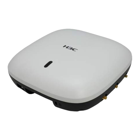
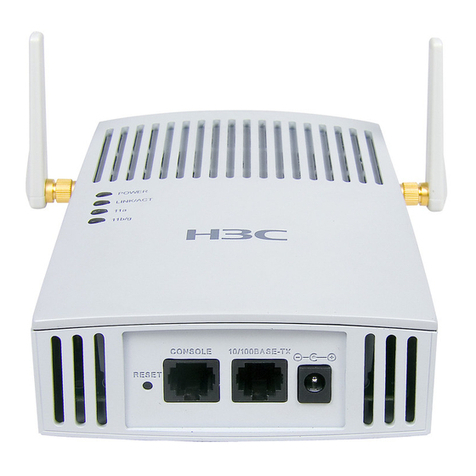
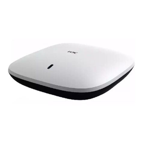
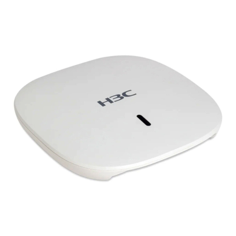
For WA2200 series models, see Figure 2
WA2200
WA2200
WA2200
WA2200
Core equipment
room Radius server
Wireless
NMS
Service
database server
Switch
Switch
Switch
Switch
Switch
Auditorium
Restaurant or
tea house
Hall or information
desk
Parking lot
PC
PC
PC
PC

6
Figure 2 Models of the WA2200 series
Table 1 Physical dimensions and weight of the WA2200 series
Model
Physical dimensions (H×W×D)
Weight
WA2210-AG/WA2220-AG,
(indoor)
40 × 166 × 118 mm (1.57 × 6.54 × 4.65
in.)
0.5 kg (1.10 lb)
WA2210X-G/WA2220X-AG,
(outdoor)
76 × 245 × 245 mm (2.99 × 9.65 × 9.65
in.)
2 kg (4.41 lb)
For details about hardware configuration, including a description of the interface and LEDs,
see Appendix A ―Technical specifications.‖
H3C WA2210-AG / WA2220-AG
H3C WA2210X-G H3C WA2220X-AG

7
2Installation preparations
This chapter describes the preparations for WA2200 installation, including unpacking and
inspection, preparation of installation tools, and environment examination.
WARNING!
Installation and removal of the unit and its accessories must be carried out by qualified personnel. Read
all Safety Instructions supplied with your device before installation and operation.
Unpacking and inspection
Before unpacking the package, ensure that the package is not damaged and that it does not
show signs of water damage. While opening the package and removing the contents, avoid
using excessive force.
The accessories vary with the models. For the exact contents of the package, refer to the
packing list. If the contents do not match the packing list, contact your H3C representative.
If the package is found to be rusted or water soaked, stop unpacking and contact your H3C
representative immediately.
Installation tools
When installing the AP, you may need the tools listed in Table 2 Select the appropriate tools
according to your installation environment.
NOTE:
The table below is only for reference. If you install the AP on a desk, none of the tools are required; if you
install the AP on or under a building eave, no digging tool is required.
Table 2 List of installation tools
Type of tool
Indoor installation
Outdoor installation
General
tools
1-meter-long ruler, marking pen, knife,
and percussion drill with matching drills
Digging tool, adjustable spanner,
and vices
Special tools
Cable stripper, crimping pliers, and
RJ-45 crimping pliers
Cable stripper, crimping pliers,
RJ-45 crimping pliers, waterproof
tape, and fiber fusion splicer
Auxiliary
tools
Ladder and rubber hammer
Ladder
Installation site examination
Before installation, examine the installation site to ensure that the AP is in a good operational
environment. Examine the installation site from the following two aspects: installation site
selection and temperature and humidity requirements. For details about temperature and
humidity requirements, see ―Temperature and humidity requirements.‖
Avoid locations that are susceptible to high temperature, dust, flame, explosives,
electromagnetic interference (high power radar, radio station, and transformer), unstable
voltage, heavy vibration, or loud noise. The installation site should be dry, without any leakage,
dripping, or dew. The AP should be at least 500 m (0.31 mi) away from a shore and should not
face the direction of onshore wind.
8
In engineering design, the site should be selected according to the network planning and
technical requirements of communications equipment, as well as considerations such as
climate, hydrology, geology, earthquake, electric power, and transportation.
After you have completed the preparations, start installing the AP. To install an indoor AP, see
Chapter 3, ―Installation (indoor).‖To install an outdoor AP, see chapter 4, ―Installation
(outdoor).‖

9
3Installation (indoor)
This chapter includes instructions for installing the WA2210-AG and WA-2220AG indoor AP
models directly on a desk or attaching it to a wall using the wall-mounting bracket.
Determining installation location
Determine the installation position by observing the following principles:
Have as few obstacles (such as wall and ceiling) as possible between the AP and stations.
Keep the AP far away from electronic devices (such as microwave oven) that may
generate RF noise.
Install the AP in a place where it will not interfere with people’s daily work and life.
Do not install the AP in an area where it may come in contact with water or condensation.
Prevent water or moisture from entering the AP.
CAUTION:
When mounting on the ceiling, ensure that the intensity and structure of the ceiling meet the
requirements for ceiling mounting. H3C recommends reinforcing weak ceilings, and securing the unit
with a padlock to prevent falloff in case of vibration or shock.
Installing the AP
This section describes how to install the AP on a wall:
Installing the wall-mounting bracket on a wall
Installing the AP on the wall-mounting bracket
Optional: Locking the AP onto the wall-mounting bracket
Installing the wall-mounting bracket on a wall
To install the wall-mounting bracket on a wall:
1. There are eight installation holes in the wall-mounting bracket. Use at least four holes for
installation. Measure and mark the wall where the AP should be mounted. Ensure holes
correspond to those in the bracket (see Figure 3 Using a 6 mm (0.24 in) bit, drill holes on the
markings.

10
Figure 3 Screw hole locations and screw hole size (in mm)
2. Insert the pointed end of anchors into the drilled holes and tap the flat end of anchors
with a rubber hammer until they are flush with the wall surface.
3. Align the holes in the wall-mounting bracket with the anchors and insert screws through
the installation holes into the anchors (see Figure 4 Position the bracket so that arrow
points up.
4. Adjust the position of the wall-mounting bracket and tighten the screws.
49.0
44.6
22.3
49.1
49.1
150.0
75.0
62.9
104.0

11
Figure 4 Install the wall-mounting bracket
Installing the AP on the wall-mounting bracket
To install the AP on the wall-mounting bracket (see Figure 5
1. Align the AP with the hooks on the wall-mounting bracket and hang the AP on the
bracket.
2. Press the AP downward to affix it.
Figure 5 Affix the indoor AP onto the wall-mounting bracket
Expansion screw
Hook
1
2

12
Optional: Locking the AP onto the wall-mounting bracket
The indoor AP has a security slot on the top, which can be used to lock the AP onto the
wall-mounting bracket to prevent theft.
To lock the AP onto the wall-mounting bracket (see Figure 6
1. Insert the locking plate into the security slot on the top of the AP.
2. Turn the locking plate counterclockwise until the hole on the locking plate is aligned with
the hole in the wall-mounting bracket.
3. Put the latch through the two holes that you aligned in the previous step.
4. Lock the latch with a lock (user-supplied).
Figure 6 Lock the indoor AP onto the wall-mounting bracket
Connecting the power supply
Local power supply
Connect the AP to the power adapter and then to the power source (see Figure 7
Locking plate
Latch
Locking hole
Wall-mounting bracket
2
1
3

13
Figure 7 Local power supply connection
Power over Ethernet (PoE)
When using PoE, you do not need to connect the power interface to a power source. You only
need to connect one end of an Ethernet cable to the Ethernet interface of the AP and the
other end to an Ethernet interface of a PoE switch (for example, Ethernet switch).
If the uplink device of the AP is a PoE switch, use an Ethernet cable to directly connect the
Ethernet interface of the AP to the PoE device (see Figure 8
Figure 8 PoE connection
TIP:
To avoid mistaking the console interface for the Ethernet interface and vice versa, locate the silkscreen
on the device .
Connecting the network
Connect the Ethernet interface of the AP to an Ethernet interface of the switch to implement
internet or MAN (Metopolitan Area Network) access (see Figure 9
Power interface
Power adapter
WA2200 PoE SwitchPC

14
Figure 9 Connect the AP to the network
Internet
WA2200
Wired station
Wireless station
Wired station
Switch

15
4Installation (outdoor)
This chapter includes instructions for installing the H3C WA2210X-G and H3C WA2220X-AG
outdoor AP models. The outdoor models are waterproof, dustproof, and lightning-proof and
can be installed on a wall or a pole. As a wireless device, the installation location directly
affects the coverage and performance of wireless signals. Therefore, H3C recommends that
the AP be installed by a professional.
NOTE:
The wall-mounting bracket is not supplied unless ordered.
Installing the AP on a wall
To install the AP on a wall:
1. To mark the bracket location on the wall, place the wall-mounting bracket at the
installation position on the wall. Mark the location of three expansion screw holes on the
wall. See Figure 10 for the distance between the expansion screw holes.
Figure 10 Wall-mounting bracket structure and positions of screw holes (in mm).
2. Using a percussion drill with a 6 mm (0.24 in) bit, drill holes on the three markings.
Observe the following precautions when drilling:
○Hold the drill handle with both hands with the bit perpendicular to the wall surface to
prevent wall damage or tilted holes.
195.0
135.0
80.0
40.070.0
220.0

16
○The hole depth should be the anchor length plus the bit length. Each hole should have
the same depth. Remove the dust from the hole before measuring the hole depth. Use
a vacuum cleaner to prevent dust from spreading.
○If the wall surface is too solid and slippery to position the bit, punch a notch first.
3. Remove dust inside and around all holes with a vacuum cleaner, and then measure the
distance between holes. If there is an error, mark and drill holes again.
4. Put an anchor into each hole vertically and tap the flat end of the anchor with a rubber
hammer until the anchor is flush with the wall surface.
5. To affix the wall-mounting bracket, align the three holes in the wall-mounting bracket with
the anchors and insert three expansion screws through the installation holes into the
anchors. Adjust the position of the wall-mounting bracket and tighten the expansion
screws.
6. Affix the AP using one of the following two methods:
Method 1: Align the two installation holes in the AP with the corresponding holes in the
wall-mounting bracket and then use two screws to affix them.
Method 2: Insert a screw into each installation hole in the AP, but do not tighten them.
Then insert the screws into the corresponding holes in the wall-mounting bracket.
7. Tighten the screws so that the AP touches the wall-mounting bracket (see Figure 11
Figure 11 Install the outdoor AP on a wall
Installing the AP on a pole
The fixing support for installing the outdoor AP on a pole consists of two major components: a pair of
V-shaped brackets and a mounting plate. The outdoor AP can be affixed on a vertical or horizontal
pole with an outer diameter of 60 to 110 mm (2.36 to 4.33 in) through the affixing support. The mounting
plate and the V-shaped bracket are affixed through the self-clinching bolt and a nut (see Figure 12 You
can first install the affixing support onto the pole and then the AP onto the mounting plate or vice versa.
Screw M6×12

17
Figure 12 Mounting plate and V-shaped bracket
To adjust the angle of the AP:
1. Follow the arrowhead (see Figure 13 to turn the V-shaped bracket with the self-clinching
bolt as the pivot to adjust the angle of the mounting plate.
2. Use tie-bar bolts through the guide slots and nuts (see Figure 15 to affix the mounting plate
and V-shape bracket.
Figure 13 Adjust the angle of the AP
On the top of a building, the outdoor AP is usually installed on a pole.
To install the outdoor AP on a pole:
1. Affix the pole base onto the top surface of a building or onto a cement pier (see Figure 14
Self-clinching bolt
V-shaped bracket
Mounting plateGuide slot
Self-clinching bolt
V-shaped bracket
Mounting plate
Guide slot

18
Figure 14 Pole and pole base
2. Affix the mounting plate onto one V-shaped fixing bracket with a self-clinching bolt.
3. Affix the pair of V-shaped fixing brackets on a vertical or horizontal pole with tie-bar bolts,
flat washers, spring washers, and nuts (see Figure 15 or Figure 16
Figure 15 Install the outdoor AP on a vertical pole
M
10
nut
10
#
flat washer
10
#
spring washer
AP
Mounting plate
V-shaped bracket
Tie
-
bar bolt
Screw M
6
×
12

19
Figure 16 Install the outdoor AP on a horizontal pole
4. Fix the AP onto the mounting plate with screws (see the dashed line and arrow in Figure 15
or Figure 16
Installing an outdoor antenna
There are two types of outdoor antennas: directional antenna and omni antenna. An omni antenna
can be directly installed onto an outdoor AP. Select an installation location for the pole so that the
antenna direction and tilt can be adjusted freely.
Installing a directional outdoor antenna on a pole
To install a pole on a parapet:
1. Weld the lightning rod onto the tip of the pole.
2. Install the pole on a parapet or cement pier.
3. Use a 40 × 4 mm (1.57 × 0.16 in) piece of flat steel to connect the pole to the ground grid.
4. Use pole-mounting brackets to install the directional outdoor antenna on the pole.
The pole should be vertical to the building top surface (see Figure 17 and Figure 18
M10 nut
10 # spring washer
10 # flat washer
AP
Mounting plate
V-shaped bracket
Tie-bar bolt
Scerw M6×12

20
Figure 17 Install a directional outdoor antenna on a parapet
Figure 18 Install a directional outdoor antenna on a building top surface or cement pier
If there are parapets around the building top and the parapets are 1200 mm (47.24 in)
high or higher, install the antenna pole on a parapet with expansion bolts and affix the
directional outdoor antenna onto the pole with pole-mounting brackets (see the diagram
on the left in Figure 17
Lightning rod
Directional outdoor antenna
Antenna support(antenna pole)
Parapet on building top
Pole-mounting brackets
500 mm
1200 mm
Φ75 mm
500 mm
1000 mm
Φ75 mm
Flat steel
To the grounding grid
Cement pier
Steel wire
Antenna support (antenna pole)
Directional outdoor antenna
Lightning rod
Φ75mm
Pole-mounting brackets
Flat steel
To the grounding grid
Other manuals for WA2200 Series
2
This manual suits for next models
4
Table of contents
Other H3C Wireless Access Point manuals