Haas TR Series User manual

Rotary - TR/TRT/T5C - Installation - Introduction
This procedure tells you how to install a TR, TRT, or T5C rotary on a Haas VMC. For these instructions, the trunnion axis is the
A Axis (TILT). The platter axis is the B Axis ( ROTARY).
Caution: Make sure the power supplied to the rotary has the correct voltage. Refer to the Machine Compatibility
section before installing a rotary table.
Haas Technical Documentation
Rotary - TR/TRT/T5C - Installation
Scan code to get
the latest version
of this document
Translation
Available
Applies to machines built from:
January, 2007
AD0005 Rev K
Copyright 2020 by Haas Automation, Inc. No unauthorized reproduction | Last Published On December 13, 2016 1/12

Caution: When you do maintenance or repair on CNC machines and their components, you must always follow basic safety
precautions. This decreases the risk of injury and mechanical damage.
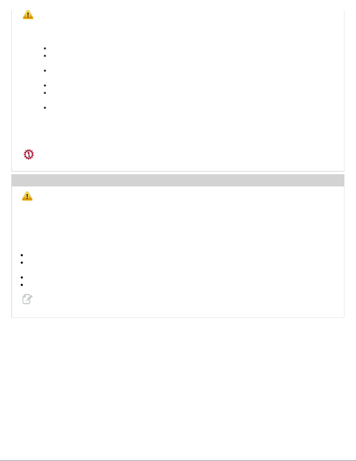
Do these steps before you do work in the machine or in the control cabinet:
Set the main circuit breaker to the [OFF] position.
Use an approved lock with an approved safety tag. Always follow lock-out procedures in accordance to local government
rules.
After turning off the machine, wait at least 5 minutes before working in the control cabinet, to allow power to dissipate. Wait
for the voltage indicator LED on the vector drive to go off completely.
Always turn off the main air supply when you work on any part of the pneumatic system.
Make sure to rest the spindle head on a block of wood when work is done on a vertical axis. This will prevent any unintended
movement that could result in the axis falling.
Never alter any safety circuits on the machine.
You should not do machine repair or service procedures unless you are qualified and knowledgeable about the processes. Serious
damage to the machine components can result in costly repairs. The service technicians at your Haas Factory Outlet (HFO) have
the training and experience, and are certified to do these tasks safely and correctly. The repair and service work performed by your
HFO is protected with a limited warranty.
Danger: Some service procedures can be dangerous or life-threatening. DO NOT attempt a procedure that you do not fully
understand. If you have any doubts about doing a procedure contact your Haas Factory Outlet (HFO) and schedule a service visit.
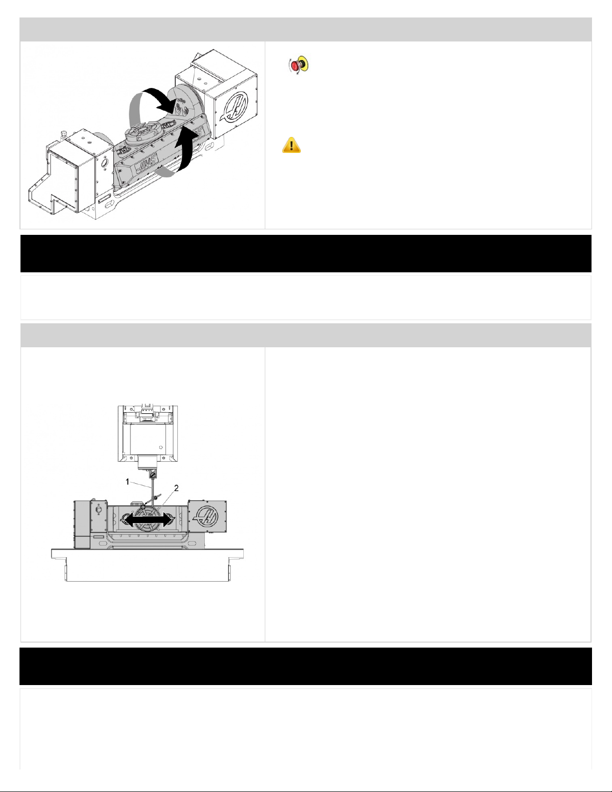
Prerequisites
Caution: The initial installation of this rotary must be done by a certified Haas Service Technician. Initial installation by
non-certified personnel invalidates the warranty of the rotary.
The machine must have a fourth and fifth axis drive installed for the rotary to operate.
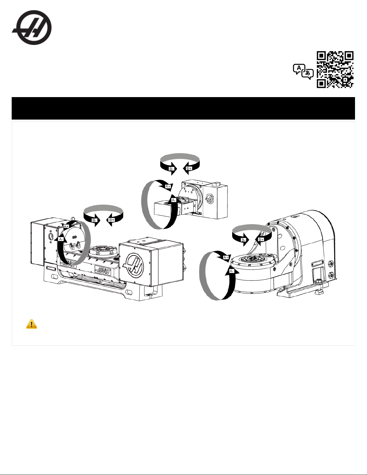
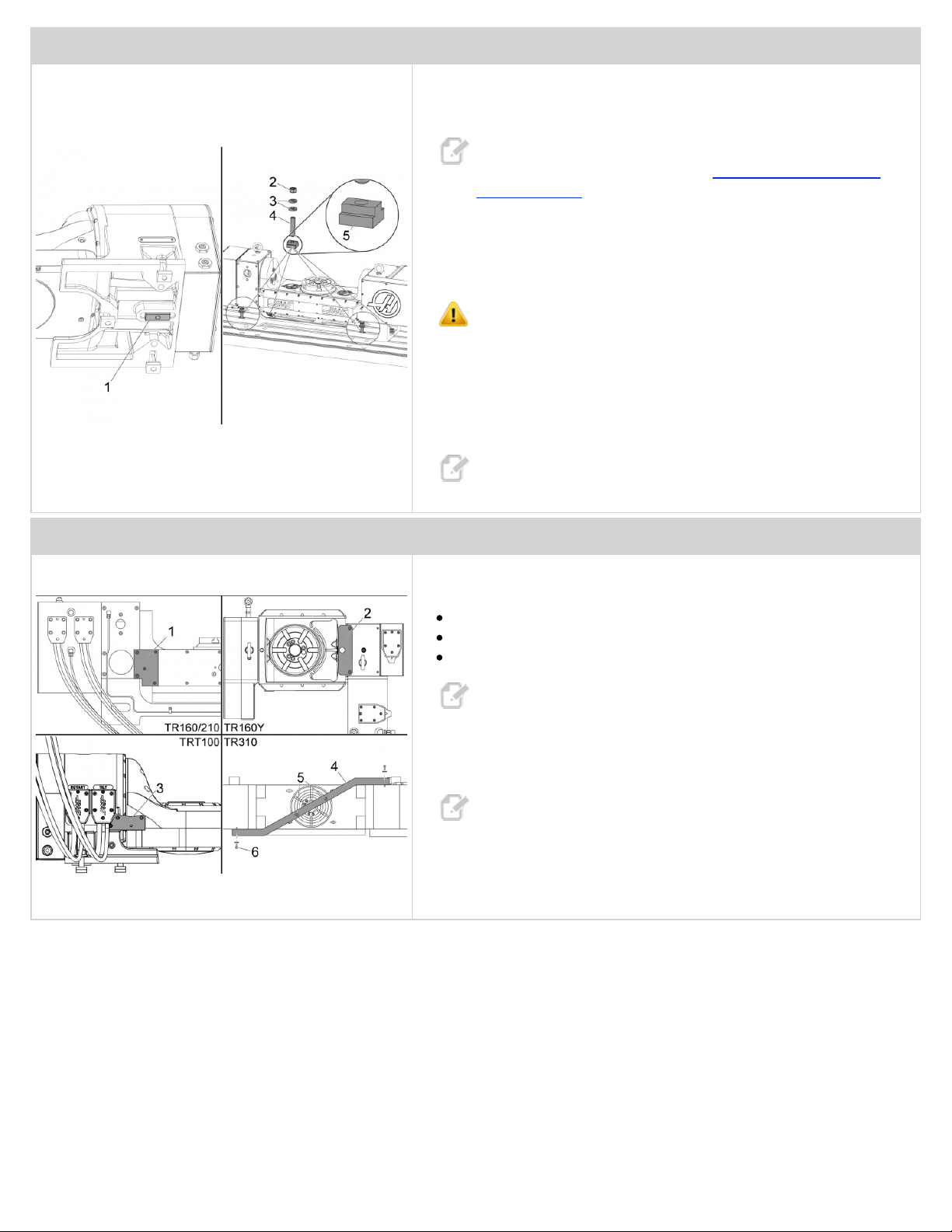
Get the name and version of the rotary model from the rotary nameplate.
Refer to the Tools Required section for images of these tools:
Lifting Chain or Strap [1] - The chain or strap must be rated for the weight of the rotary.
Spreader Beam [2] - A spreader beam is recommended to keep the lifting chains vertical. It must be rated to the weight for
the rotary. The width of the spreader beam must be the same as the width between the lifting eye bolts.
Lifting Device [3] - A lifting device, such as a forklift, lifting hoist, etc, must be rated for the weight of the rotary.
Dial Indicator [4] - The dial indicator must be able to measure 0.0001” (0.003 mm)
Note: To find the weight of your rotary go to www.haascnc.com. Search for your rotary. Select it from the list results. The
weight will be listed in the "Specifications" section.
Copyright 2020 by Haas Automation, Inc. No unauthorized reproduction | Last Published On December 13, 2016 2/12

Machine Compatibility
Do this procedure for these machines:
All VMCs
For a TRT100, the machine must have software version M18.24A or higher.
It may be necessary to change a cable in the control on these machines:
Trunnions made after October, 2016:
Mills with Classic Haas Control (CHC) or Next Generation Control (NGC) made before October, 2016:
4th axis scale enabled:
Remove cable CABLE, [+12V] ROTARY SCALE FEEDBACK CONTROL END (CHC) (P/N 32-10065) or
cable CABLE, [+12V] ROTARY SCALE FEEDBACK CONTROL END (NGC (P/N 32-10053) from the control.
Install cable CABLE, [+5VDC) ROTARY SCALE FEEDBACK CONTROL END (CHC,NGC) (P/N 32-10049).
4th axis scale not enabled
Install cable CABLE, [+5VDC) ROTARY SCALE FEEDBACK CONTROL END (CHC,NGC) (P/N 32-10049).
Mills with CHC or NGC made after October, 2016:
No change necessary.
Trunnions made before October 2016
Mills with CHC or NGC made before October, 2016:
No change necessary.
Mills with CHC or NGC made after October, 2016:
4th axis scale enabled
Remove cable CABLE, [+5VDC) ROTARY SCALE FEEDBACK CONTROL END (CHC,NGC) (P/N 32-
10049) from the control.
Install cable CABLE, [+12V] ROTARY SCALE FEEDBACK CONTROL END (NGC) (P/N 32-10053).
4th axis scale not enabled
Install cable CABLE, [+12V] ROTARY SCALE FEEDBACK CONTROL END (NGC) (P/N 32-10053).
Tools Required
Lifting Chain [1]
Spreader Beam [2]
Lifting Device [3]
Dial Indicator [4]
Copyright 2020 by Haas Automation, Inc. No unauthorized reproduction | Last Published On December 13, 2016 3/12

Rotary - TR/TRT/T5C - Installation
STEP 1
Push ZERO RETURN. Push ALL.
Move the machine table [1] to the position nearest to the doors.
Push [EMERGENCY STOP].
Connect the rotary air hose to an air supply. The air pressure engages the brake on each rotary axis to prevent internal damage.
Caution: Make sure the air hose has sufficient length to prevent damage to the rotary when you install it.
STEP 2
Install the eye bolts included with the rotary.
Install the lifting chains [1] and the spreader beam [2].
Refer to the "Rotary - TR/TRT/T5C – Lifting Instructions" at the end of the
procedure for more information.
Caution:
Use a spreader beam, chains, and the air hose connected
to an air supply to prevent damage to the rotary.
Use a spreader beam to make sure the chains stay vertical.
Make sure the TILT Axis is flat to prevent damage to the
rotary. If the TILT Axis is not flat, speak to your Haas
Factory Outlet (HFO).
Copyright 2020 by Haas Automation, Inc. No unauthorized reproduction | Last Published On December 13, 2016 4/12

STEP 3
Install the T-Nuts [5] on the machine table. If necessary, install the
locating pins or alignment keys [1] for your rotary.
Note: To see if your rotary has locating pins or alignment keys go
to DIY.HAASCNC.com. Search for Rotary - Locating Pins or
Alignment Keys. Click "Rotary - Locating Pins or Alignment Keys"
and find your rotary on the list.
Make sure the machine table and the bottom of the rotary are clean.
Use a lifting device, to put the rotary on the table.
Caution: If necessary, get a second person to help carefully
move the rotary into the machine.
Remove the eye bolts and the lifting chains or straps. Install (1) 1/2-13
double-threaded stud [4], (2) washers [3], and (1) nut [2] on each T-Nut.
Use your hand to tighten the nut. This lets you make adjustments when
you align the rotary.
Note: For some rotaries, you must turn (“tilt”) the A Axis to install
all of the double-threaded studs, washers, and nuts.
STEP 4
Remove the standoffs and the shipping brackets from these locations:
The right rear [1] of a TR160/210.
The top [2] of a TR160Y.
The rear center [3] of a TRT100.
Note: The TRT160, TRT210, and T5C do not have shipping
brackets.
For a TR310, remove the (4) 1/2-13 screws and washers [5] and [6] from
the shipping bracket [4]. Remove the (2) T-Nuts from the rotary platter.
Note: Keep all of the hardware and the shipping brackets.
In the same location, install the screws that you removed from the
shipping bracket. This prevents contamination from coolant in the rotary
unit. Do not install the screws you removed from the platter.
Copyright 2020 by Haas Automation, Inc. No unauthorized reproduction | Last Published On December 13, 2016 5/12

STEP 5
Clean the machined surfaces of the rotary.
Note: Use a pH-neutral degreaser. For example: WD-40,
Sunnyside Odorless Mineral Spirits, or Benz Oil Sta-brite 306.
Release [EMERGENCY STOP].
Jog the X and Y axis to the Home position.
Disconnect the rotary air hose from the air supply.
Remove the shipping plate [2] from the cable clamp [1]. Discard the
shipping plate.
Install the cable clamp on the enclosure. Use (1) of the 1/4-20 x 2"
thumbscrews [3]. Leave the thumbscrew loose.
Note: The cable clamp mounting holes [4] are in different
locations on some machines.
STEP 6
Push [EMERGENCY STOP].
Push [POWER OFF].
Set the main circuit breaker to the OFF position.
Lock the main circuit breaker. Use an approved lock with an approved safety tag.
STEP 7
Put the rotary air hose into the enclosure through the front door.
Put the air hose through the hole in the top of the enclosure near the
cable clamp you installed in Step 5.
Put the cable along the side of the machine to the bottom.
For CALM [1] machines, connect the air hose to the machine in the CALM
cabinet.
For Pre-CALM [2] machines, connect the air hose to the machine below
the control cabinet.
Copyright 2020 by Haas Automation, Inc. No unauthorized reproduction | Last Published On December 13, 2016 6/12

STEP 8
Make sure each group of the remaining rotary cables are straight and do
not twist around the other cables.
The rear of the rotary has labels for the cable connections. The labels are
TILT (A Axis) [1] and ROTARY (B Axis) [1].
Put an "A Axis" label on the control end of the TILT cable.
Put a "B Axis" label on the control end of the ROTARY cable.
Put the cables along the same path as the air hose that exits the
enclosure.
Put the cables over the side of the machine. Put (1) cable [3] from the
rotary unit through the cable clamp [2]. Do not tighten the thumbscrew at
this time.
Pull the cables and the air hose until they have tension from the rotary to
the cable clamp. Zip-tie the cables together.
Caution: Make sure the cables have sufficient tension to let them
hang from the hole but to not touch the table. Make sure the
cables do not travel in a straight line from the hole to the rotary.
Install the last (1) 1/4-20 x 2" thumbscrew into the cable clamp. Tighten
the thumbscrews.
STEP 9
Remove the dust covers [3] from the connection ports for the A- and B-
Axes. The connections are on the side of the control cabinet.
Caution: Before you connect the cable, make sure the power is
off. If the power is on, this causes damage to the electrical
components.
Connect the TILT and ROTARY axis cables [2].
If the VMC has A-Axis Scales, connect the rotary scale cable [1] to the
port SCALE A Axis.
If the VMC does not have A-Axis Scales, wrap the cable into a coil. Put
the cable between the mill enclosure and the control cabinet.
Set the main circuit breaker to the ON position.
Push [POWER ON].
STEP 10
If your machine has the Next Generation Control (NGC):
1. Do the Next Generation Control - Rotary - Enable and Disable procedure.
2. Go to step 13.
Copyright 2020 by Haas Automation, Inc. No unauthorized reproduction | Last Published On December 13, 2016 7/12

STEP 11
Go to Setting 7. Set the PARAMETER to OFF.
In PARAMETER 315 enable FOURTH AXIS and FIFTH AXIS.
Change setting 30 4TH AXIS ENABLE to NEW.
Push [ENTER].
Select the correct rotary model and axis.
Note: For example, if the nameplate is TR210 Ver. P4, select
TR210-P4-TLT.
Push [ENTER].
Note: On some machines, not all rotary models are available on
setting 30 4TH AXIS ENABLE.
If your rotary model is not available, you must select USER1 for the A
axis.
Use a parameter list to enter all the A-Axis parameters . If you do not
have a parameter list, speak to your Haas Factory Outlet (HFO).
STEP 12
Change Setting 78 5TH AXIS ENABLE to NEW.
Push [ENTER].
Select the correct rotary model and axis.
Note: For example, if the nameplate is TR210 Ver. P4, select
TR210-P4-ROT.
Push [ENTER].
Note: On some machines, not all rotary models are available on
setting 78 5TH AXIS ENABLE.
If your rotary model is not available, you must select USER2 for the B
axis.
Manually enter all the B axis parameters using a parameter list. If you do
not have a parameter list, speak to your Haas Factory Outlet (HFO).
Push [POWER OFF].
Push [POWER ON].
Release [EMERGENCY STOP].
Copyright 2020 by Haas Automation, Inc. No unauthorized reproduction | Last Published On December 13, 2016 8/12

STEP 13
Push ZERO RETURN. Start with the X Axis.
Caution: If the A axis (tilt) moves more than 20 degrees past the
home position,
Push [EMERGENCY STOP] to prevent damage. Make sure
that you selected the correct rotary model for setting 30, 4TH
AXIS ENABLE and setting 78, 5TH AXIS ENABLE. If you
selected the correct rotary model and axis, speak to your Haas
Factory Outlet (HFO).
Jog the table to the maximum travel in each axis.
Caution: Make sure the cables do not get caught on the table or
get crushed between the table and the enclosure to prevent
damage.
Turn ("tilt") A axis to get access to the T-Nuts.
Push [EMERGENCY STOP].
Install the remaining studs, washers and nuts.
Rotary - TR/TRT/T5C - Platter Parameter 212 - Horizontal Adjustment
This procedure tells you how to make the platter parallel to the Y-Axis movement. You change Parameter 212 to make the
platter parallel.
STEP 1
Push ZERO RETURN. Push A.
Put the magnetic base of a dial indicator on the spindle head.
Jog the X axis to center the platter on the spindle. Jog the Y
and Z axis until the indicator is above the platter edge. Make
sure you can indicate the full diameter from front to back.
Set the indicator to zero. Indicate the platter or collet face along the Y
Axis. If the error is more than 0.0003" (0.008mm) adjust Parameter 212 in
small increments in the positive (+) or negative (-) direction to adjust the
flatness.
Push ZERO RETURN. Push A.
Do this step again until the error is less than 0.0003" (0.008mm).
Copyright 2020 by Haas Automation, Inc. No unauthorized reproduction | Last Published On December 13, 2016 9/12

STEP 2
Release [EMERGENCY STOP].
To make sure the travel limits of the A axis are correct [HANDLE JOG] in
the positive and the negative direction. Make sure the movement stops at
120 degrees in each direction.
Caution: Stop jogging the axis if the A axis (tilt) moves more
than 120 degrees. Make sure that Setting 30 4TH AXIS ENABLE
and Setting 78 5TH AXIS ENABLE are correct. If the settings are
correct and the A axis (tilt) still moves more than 120 degrees,
speak to your Haas Factory Outlet (HFO).
Rotary - TR/TRT/T5C - Alignment
This procedure tells you how to align a multi-axis trunnion to the table. The platter or the collet face must be parallel to the X-
axis movement. The error cannot be more than 0.0003" (0.008 mm).
STEP 1
Tilt the A axis to 90 degrees.
Put the magnetic base of a dial indicator [1] on the spindle head.
Jog the X axis to center the platter [2] on the spindle. Jog the Y and Z
axis until the indicator is in front of the platter, near the edge. Make sure
you can indicate the full diameter from left to right.
Set the indicator to zero.
Indicate the platter or collet face along the X Axis. If the error is more than
0.0003" (0.008mm) use a rubber or plastic mallet to adjust the position of
the rotary. On the side near the front doors, adjust the rotary by lightly
tapping on the rotary base. Watch the indicator while making adjustments.
Repeat this step until the error is less than 0.0003" (0.008mm).
If the error is within range tighten all of the screws. Indicate along the X
axis to make sure the rotary did not move. If the error is more than
0.0003" (0.008mm) lossen the screws. Adjust the position of the rotary.
Watch the indicator while making adjustments. Repeat this step until the
error is less than 0.0003" (0.008mm).
If the error is within range the installation is complete.
Rotary - TR/TRT/T5C - Lifting Instructions
Lift the rotary table with the lift rings as shown to prevent damage to the gear set. Attach an air supply to the rotary before you
lift it. All rotary tables (HRT's, TR's TRT's and T5C's) use the 1/2-13 eyebolts. Haas Automation, Inc. does not supply lifting
chains or straps for rotary products.
Copyright 2020 by Haas Automation, Inc. No unauthorized reproduction | Last Published On December 13, 2016 10/12

If spreader bars are not available, eyebolts may be used as shown:
Copyright 2020 by Haas Automation, Inc. No unauthorized reproduction | Last Published On December 13, 2016 11/12

Copyright 2020 by Haas Automation, Inc. No unauthorized reproduction | Last Published On December 13, 2016 12/12
This manual suits for next models
12
Other Haas Industrial Equipment manuals

Haas
Haas HSF-325 User manual

Haas
Haas MDC-500 User manual

Haas
Haas Automatic Pallet Changer User manual

Haas
Haas Bar Feeder User manual

Haas
Haas EC-400 Installation instructions

Haas
Haas ATT-4 User manual

Haas
Haas TSC-300/1K Guide

Haas
Haas Bar Feeder User manual

Haas
Haas SL-20 User manual

Haas
Haas DT-1 Use and care manual
Popular Industrial Equipment manuals by other brands

Parker
Parker Compax3M Series Short description

GRUNDFOS ALLDOS
GRUNDFOS ALLDOS Oxiperm C 164 Series Operation and service manual

Emerson
Emerson Penberthy Installation, operation and maintenance instructions

CKD
CKD M4G Series instruction manual

Rockwell Automation
Rockwell Automation Allen-Bradley VersaVirtual Series user manual

Nexo
Nexo VXT-BL515 manual