Haas Automatic Pallet Changer User manual

96-0012 rev G 1
June 2003
OM
PERATOR’S ANUAL
Automatic
Autom a t i c
Automatic
Autom a t i c
Pallet Changer
Pallet Changer
INTRODUCTION
1.0 AUTOMATIC PALLET CHANGER (APC)
1.1 OVERVIEW
IMPORTANT!
Read this entire section before attempting to install or run the APC. Serious in ury or dam-
age to the machine could result from not following these procedures.
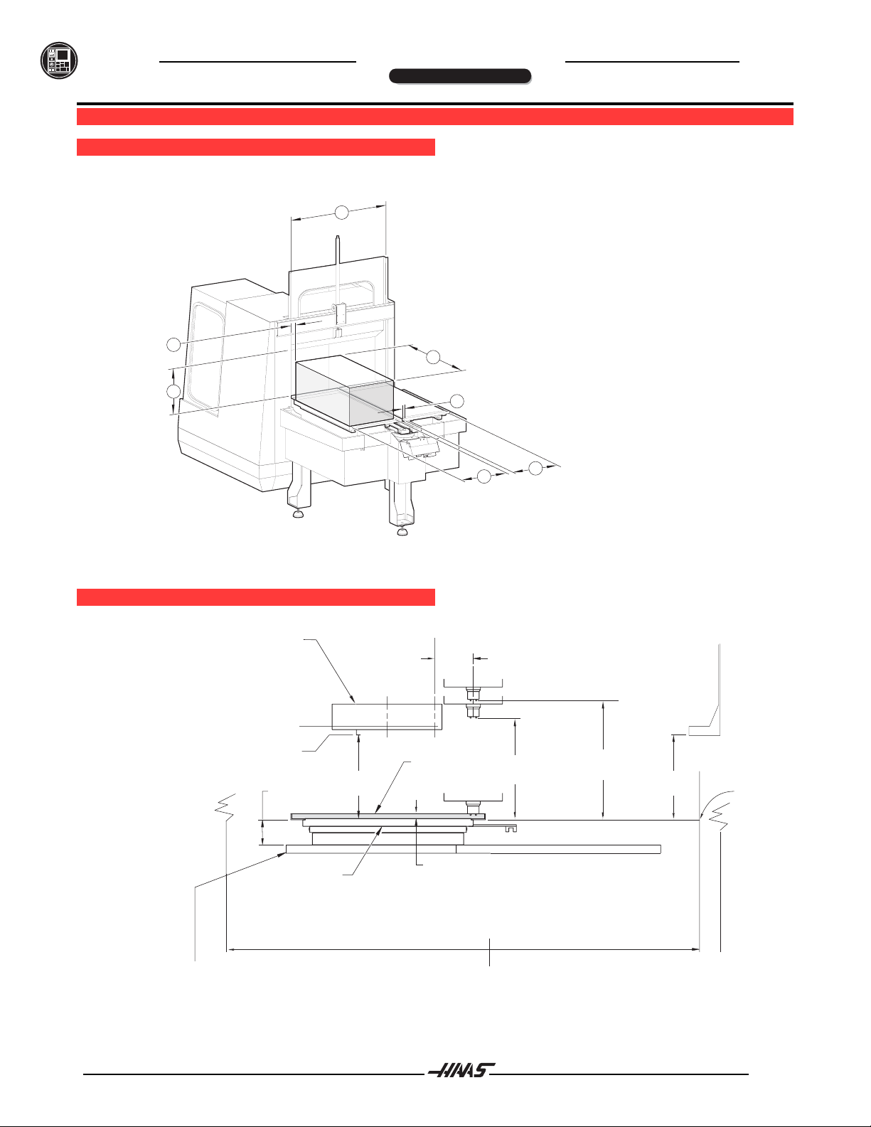
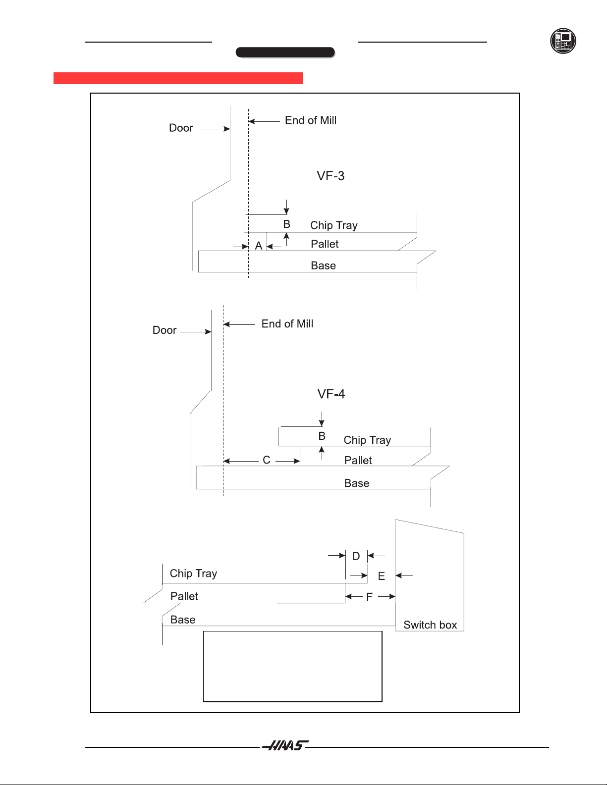
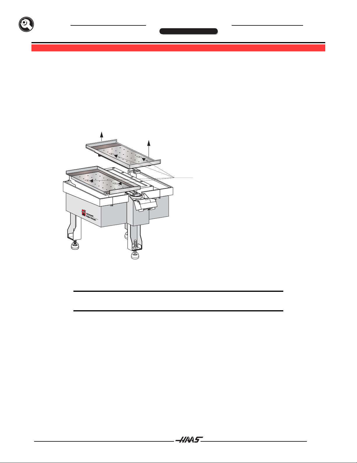
The HAAS Automatic Pallet Changer (APC) is used to automatically load and unload pallets into a HAAS VF-3
or VF-4 The APC is controlled by the VMC control, and uses the same air and power supplies A simple M
code (M50) is all that is required to change pallets
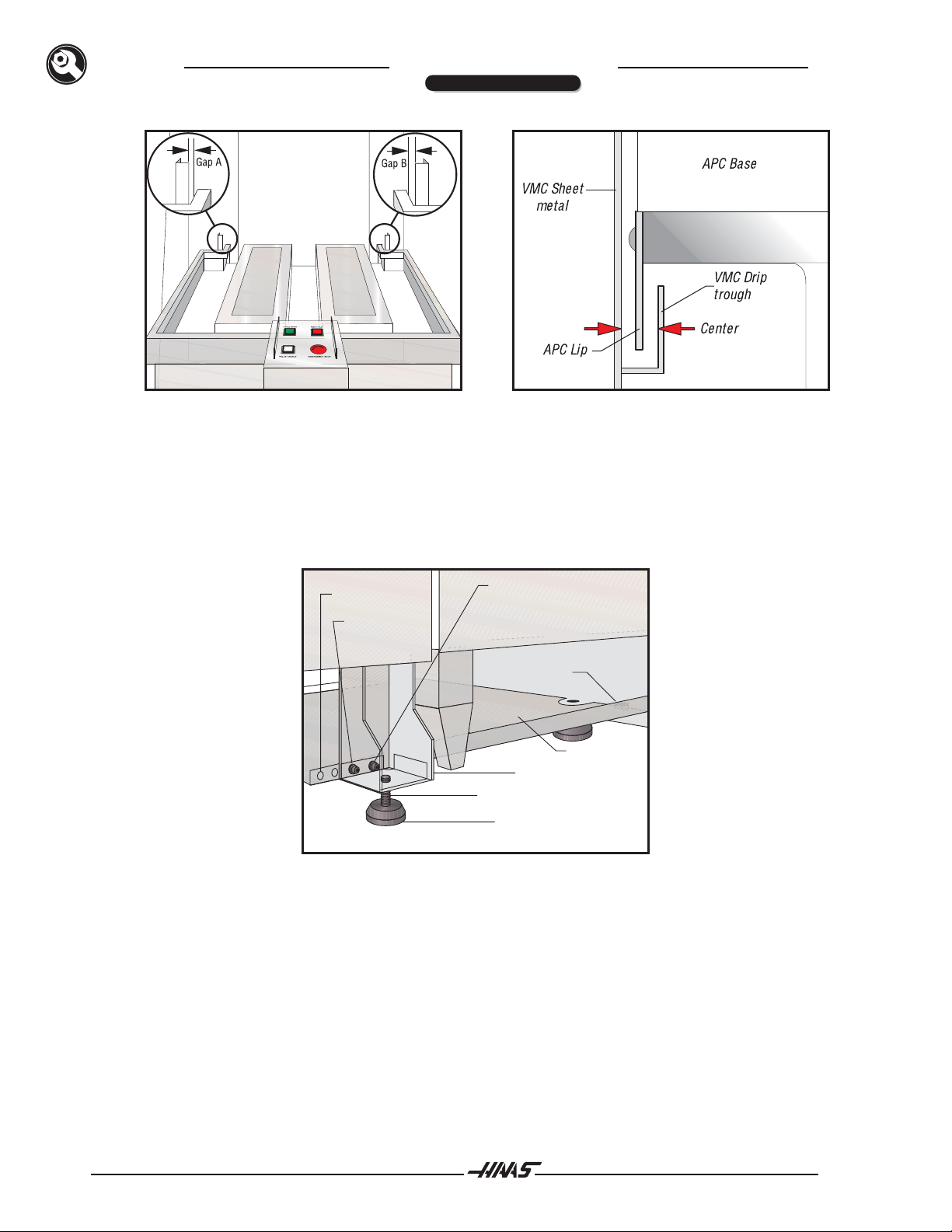
The APC assembly consists of the base, which serves as the home position for the two pallets, and a receiver
assembly, which is bolted to the VMC table and holds the pallets in place during machining operations The
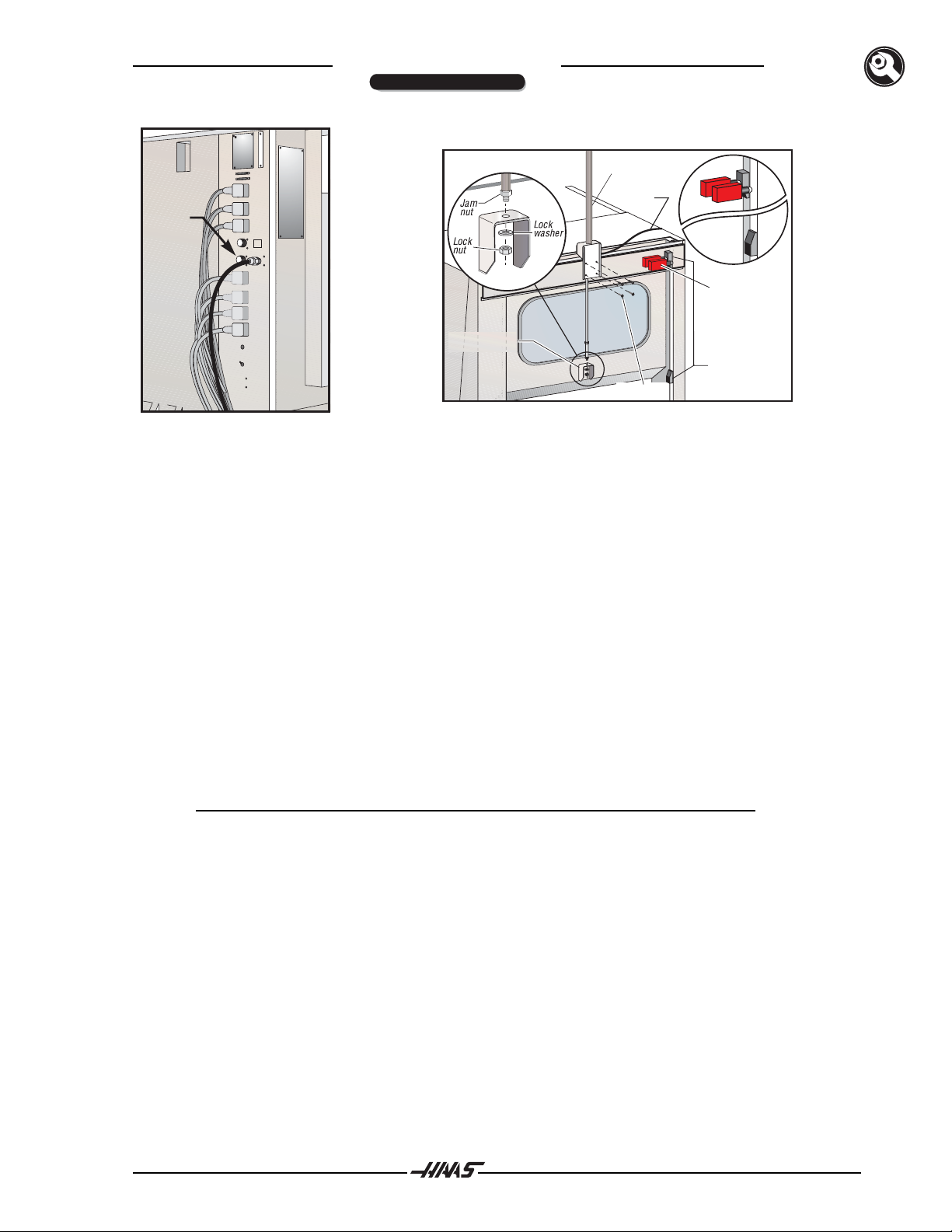
VMC unit contains air lines for clamping pallets, and a special automatic door in the side of the VMC enclosure
allows for loading and unloading of pallets The APC has its own operator's panel, which includes CYCLE
START, FEED HOLD, PALLET READY, and EMERGENCY STOP buttons
The APC can be programmed to load a pallet or change pallets by calling an M50 When a pallet change is
programmed, the VMC table moves to the right and adjacent to the empty pallet position on the APC base The
receiver assembly then unclamps the pallet The automatic door opens, the table moves to the unload position,
and the pallet is pulled into its home position The VMC table moves over to the other pallet position, the next
pallet is pushed onto the receiver, and the pallet is clamped into position The table then returns to its pro-
grammed position and the door closes
Pallet movement is accomplished through the use of a drive motor and chain The drive motor has a nonadjust-
able slip clutch that prevents damage to the motor if the pallet change is physically blocked
NOTE: The machine will beep during a pallet change. This is an audible warning
signal, and not an alarm.

296-0012revG
June 2003
OM
PERATOR’S ANUAL
Automatic
Autom a t i c
Automatic
Autom a t i c
Pallet Changer
Pallet Changer
INTRODUCTION
1.2 APC WORKING DIMENSIONS
B
A
D
C
C
E
F
A.
B.
C.
D.
E.
F.
20” (50.8 cm) DOOR HEIGHT ABOVE PALLET.
40“ (101.6 cm) DOOR OPENING WIDTH.
19“ (48.26 cm) PALLET WIDTH.
3/8“ (.95 cm) DISTANCE BETWEEN PALLETS.
1/2“ (1.27) DISTANCE BETWEEN PALLET AND DOOR
.
40“ (101.6) PALLET LENGTH.
APCDIMENSIONS
APCWORK ENVELOPES
OF TOOL HOLDER V-GROOVE
LOWEST POINT ON CAROUSEL
9" (22.86 cm)
C
L0F TOOL HOLDER
TOOL CHANGER COVER
C
L
21.69"
(55 cm)
TOOL
CHANGE
POSITION
26"
(66 cm)
MAX Z-AXIS
TRAVEL
MILL TABLE (AT HOME POSITION)
SIZE: VF-3 48" x 18", (121.92 cm x 45.72 cm)
TRAVEL: VF-3 40" x 20", (101.60 cm x 50.80 cm)
ENCLOSURE USEABLE WORK SPACE
19.38”
(49.23 cm)
CHIP TRAY
PALLET
1.38” Chip Tray
(3.51 cm)
5.8
(14.23 cm)
20“
(50.8 cm)
APC DOOR
OPENING
58”
(147.32 cm)
46”
(116.84 cm)
Top o f
Pallet

96-0012revG 3
June 2003
OM
PERATOR’S ANUAL
Automatic
Autom a t i c
Automatic
Autom a t i c
Pallet Changer
Pallet Changer
INTRODUCTION
APCPALLET CLEARANCES
A1-1/4” D 3*
B1-3/8”* E 1-1/2”*
C6-1/4” F 4-1/2”*
*Thesame for both VF-3 and VF-4

496-0012revG
June 2003
OM
PERATOR’S ANUAL
Automatic
Autom a t i c
Automatic
Autom a t i c
Pallet Changer
Pallet Changer
2.0 MAINTENANCESCHEDULE
Thefollowing is a list of required regular maintenance for the HAASAutomatic Pallet Changer.Thesespecifica-
tions, especially the daily routine maintenance, must be followed in order to keep your machine in good
workingorder and to protect your warranty.
PERIODIC MAINTENANCE
INTERVALMAINTENANCE PERFORMED
IMPORTANT!! Damage or misalignment may result from neglect of
daily maintenance.
DAILY Clean chips, coolant, and other debris from theAPC and receiver areas. Pay
special attention to the receiver clamping bars, and the pallet clamping rails
and wipers. Clean chips and coolant from receiver pallet clamped switch.Apply
a light coat of grease and work the grease into the plunger. Do not over grease.
WARNINGWARNING
WARNINGWARNING
WARNING:
Excessive chip buildup will require more frequent chip cleanup.
Cleanthe two locating pins in the receiver base and the corresponding bushings in
the pallets.Apply a very light coat of general purpose grease to the pins and
bushings,ifneeded.
Cleanexcessive chips and coolant from pallet drive chain.
WEEKLY Remove the two 1/4" screws from the control panel and rotate to open position.
Clean chips and coolant from the drive sprocket and limit switch.Apply a light
coat of general purpose grease and work the grease into the switch plungers.
Check air gauge/regulator at the VMC lube/air panel for 85 psi.
Checkcondition of wipers. There are two wipers oneach pallet.
INTERVAL MAINTENANCEPERFORMED
MONTHLY Check door for proper operation, both up and down. Clean and grease door side
guiderailsasrequired.
MAINTENANCE

96-0012revG 5
June 2003
OM
PERATOR’S ANUAL
Automatic
Autom a t i c
Automatic
Autom a t i c
Pallet Changer
Pallet Changer
INSTALLATION
3.0 INSTALLATION
TOOLSREQUIRED:
•Machinists'level(2) •Forklift capable of lifting 5,000 lbs, with forks at least 6' long
•6'straightedge •Included - APC chain rotation tool (P/N 20-0102)
•Allenwrenches •Included - APC jumper
Prior to installing your VMC, make certain that there is enough floor space on the right-hand side of the VMC to
place theAPC. TheAPC will add approximately 52 1/2" (58 1/2" for the VF-4) to the width of the VMC. Ensure
thatall the air and power requirements for theVMC have been met.
GENERAL REQUIREMENTS
OperatingTemperatureRange 41°F to 104°F (5 to 40°C)
StorageTemperatureRange -4°F to 158°F (-20to 70°C)
AmbientHumidity: less than 90% relative humidity,non-condensing
Altitude:0-7000 ft.
3.1VF/APCFOOTPRINT
VF 3/4 WITH APC FOOTPRINT

696-0012revG
June 2003
OM
PERATOR’S ANUAL
Automatic
Autom a t i c
Automatic
Autom a t i c
Pallet Changer
Pallet Changer
3.2 ROUGH LEVELING / ALIGNMENT
In this section, theAPC will be set in place and roughly aligned to the VMC. When the alignment procedure is
complete, the rollers on the VMC receiver and on theAPC base will be at the same height and aligned with
each other. In the "Fine Tuning" section, theAPC will be aligned more precisely by adjusting variables in the
VMC control.
1. RemovetheAPC from its shipping crate. Remove all tie-downs and strapping materials. Remove
the pallet shipping bolts and install the socket set screw plugs with Loctite (see Figure 3.1). Lift
off the pallets and set them aside. Remove the door air cylinder and the cable bundle from their
storage positions in theAPC pan.
1
2
Remove pallet shipping bolts
and install 1/2”-13 plugs. Use
Loctite. Visually check to verify
that plugs do not extend into
roller channels. It is important to
install the plugs to prevent chips
from falling under the pallets and
causing possible damage.
Figure 3.1 Removal of Shipping Bolts
CAUTION! The pallets have wipers on the bottom of the clamp rails at the VMC
end. These wipers should overhang any temporary storage position.
2. Important! Before installing theAPC, ensure the VMC has been installed and leveled. Also make
sure theAPC jumper is installed in the "5thAxis" port on the side of the VMC control cabinet (see
Figure3.2).
INSTALLATION

96-0012revG 7
June 2003
OM
PERATOR’S ANUAL
Automatic
Autom a t i c
Automatic
Autom a t i c
Pallet Changer
Pallet Changer
5th Axis
Port
Door Bracket
Air Line
Door
Switches
Air Cylinder
BHCS (4)
Trip
Blocks
Figure 3.2 Fifth Axis port on the side of the Figure 3.3 Air cylinder installation.
VMC control cabinet
Installing Door Air Cylinder
3. Remove the lock nut and washer from the end of the air cylinder rod, but leave the jam nut in place.
Connect the automatic door air cylinder and bracket to the machine with four 1/4"-20 BHCS, as
shownin Figure 3.3.
4. Insert the air cylinder rod into the door bracket, then attach the lock nut and washer to the bottom
of the cylinder rod.
5. Install the door switches and bracket onto the VMC with two SHCS each. Insert the door air line
into the fitting at the base of the air cylinder.
6. POWER ON the VMC and ZERO RETURN all axes. Verify that the VMC operates normally.
7. In MDI mode, command an M17. The table will unclamp (raise) and the automatic door will open.
The door and table will stay up. Clean all shipping protectant from the rollers, alignment pins and
clamp bars.
NOTE: M14 will move the table slowly in case a pallet is present.
Positioning the APC
8. Raise theAPC with the forklift and install the leveling screws into the legs. As a preliminary height
setting, turn the screws until the length of screw extending above theAPC leg is the same as the
lengthof VMC leveling screw extending above the VMC base. Set the leveling pads (3) in place.
9. Set theAPC in place on the leveling pads, so that it is centered in the VMC door opening (see
Figure 3.4). Ensure that the lip of theAPC enclosure is centered in the VMC drip trough (see
Figure3.5).
INSTALLATION

896-0012revG
June 2003
OM
PERATOR’S ANUAL
Automatic
Autom a t i c
Automatic
Autom a t i c
Pallet Changer
Pallet Changer
Figure 3.4 Gaps A and B should be equal. Figure 3.5 The APC lip should be centered
in the VMC drip trough.
10. Attach theAPC brace to the VMC and the APC with six screws (four 3/8" screws in the APC legs
and two 1" screws in the VMC base), but DO NOT TIGHTEN (see Figure 3.6). The VF-3 uses the
two holes in the brace that are closest to the VMC, while the VF-4 uses the two holes farthest
from the VMC.
Leveling Pad
Leveling Screw
APC Leg
APC Brace
3/8“SHCS (4)
VMC Base
HHB (2)
VF-4 Holes (2)
VF-3 Holes (2)
Figure 3.6 Installing the APC brace shown).
11. In MDI mode, command an M14. The table will move to the pallet #1 load position. (The front right
corneroftheVMC).
12. Place the straightedge on top of the rollers of both the VMC receiver (unclamped) and theAPC, to
check theAPC height (see Figure 3.7). Make sure that the straightedge is on top of at least two
rollers on both the unclamped receiver and theAPC in order to get an accurate reading. Adjust the
leveling screws in theAPC legs until the straightedge lays completely flat on all rollers.
INSTALLATION

96-0012revG 9
June 2003
OM
PERATOR’S ANUAL
Automatic
Autom a t i c
Automatic
Autom a t i c
Pallet Changer
Pallet Changer
Figure 3.7 APC roller alignment setup.
13. Place the straightedge against the side of the rollers on the VMC receiver and theAPC, to ensure
that the rollers are aligned in the Y-axis. The straightedge must extend past at least two rollers on
both theAPC and VMC to get an accurate reading.
If the rollers are not parallel, the APC must be moved. The APC can be moved slightly by tapping on the
levelingpadswith a hammer.
NOTE: If the rollers are parallel, but are not aligned, the adjustments will be made later
in the "Fine Tuning" section.
14. In MDI mode, command an M15. The table will move to the pallet #2 load position (right rear corner
of the VMC). Repeat Steps 12 and 13 with the table in this position.
15. Tighten down the four 3/8 SHCS and two hex-head bolts (see Figure 3.6) on theAPC brace
evenly, so theAPC is not pulled out of alignment. Recheck the level and all alignments.
Setting up the APC
16. OpenthehingedAPC operator's panelcoverbyremovingthetwoBHCS(seeFigure3.8).
INSTALLATION

10 96-0012revG
June 2003
OM
PERATOR’S ANUAL
Automatic
Autom a t i c
Automatic
Autom a t i c
Pallet Changer
Pallet Changer
Figure 3.8 APC operator's panel cover.
17. Ensure that the drive roller on theAPC chain is centered under the control box, as shown in Figure
3.9. If not, use the chain position adjustment tool to rotate it into this position.
To use this tool, place it into the center of the drive sprocket with the key in the sprocket's keyway (see Figure
3.10). Note that the tool only goes about 1/4" into the sprocket. Push down and turn the tool with a wrench in
order to position the chain.
Important! Remember to remove the adjustment tool when finished.
Figure 3.9 Chain drive roller positioning. Figure 3.10 Chain position adjustment tool placement.
18. Insert two 1/2"-13 eyebolts into each pallet (see Figure 3.11).Attach straps or chains to the
eyebolts, and use a forklift or hoist to lift each of the pallets onto theAPC. Ensure that each pallet
is placed with it's drive leg pawl under theAPC operator's panel, and that theAPC rollers fit into
the grooves on the bottom of the pallets (see Figure 3.12).
NOTE: Be careful not to set the pallets on top of the chain drive roller. If necessary,
rotate the chain slightly using the chain position adjustment tool.
INSTALLATION

96-0012revG 11
June 2003
OM
PERATOR’S ANUAL
Automatic
Autom a t i c
Automatic
Autom a t i c
Pallet Changer
Pallet Changer
CAUTION! Use extreme caution when moving the pallets; each pallet weighs
300 lbs., and can cause serious injury. Be careful not to damage the
pallets or the APC rollers.
1/2“ - 13 Eyebolts
Pallet
Pallet Drive Leg Drive Leg Detent
Drip Pan
Clamp Rail
Wiper
(2)
(2)
1
2
Remove pallet shipping bolts
and install 1/2”-13 plugs. Use
Loctite. Visually check to verify
that plugs do not extend into
roller channels. It is important to
install the plugs to prevent chips
from falling under the pallets and
causing possible damage.
Figure 3.11 Lifting eyebolt locations. Figure 3.12 Pallet placement.
19. Pull the pallets onto the friction blocks and against the hard stop (see Figure 3.13). Rotate the
chain slightly, using the chain position adjustment tool, to allow each drive leg detent to clear the
chaindriveroller.
Figure 3.13 View of APC base showing friction block and hard stop.
20. Power OFF the VMC.
WARNING!WARNING!
WARNING!WARNING!
WARNING!
This will cause the automatic door to fall. Keep hands clear.
21. Remove the jumper from the FifthAxis (B) port on the side of the VMC control cabinet (see Figure
3.2), and insert theAPC amphenol connector into this port.Tie-wrap the cable to the door switch
cable and the air hoses at the rear of the VMC.
22. Screw the air blast hose into theAPC. Remove the piece of tubing from the top fitting of the VMC
lube/air panel cross fitting, and replace it with theAPC air hose (see Figure 3.14).
INSTALLATION

12 96-0012revG
June 2003
OM
PERATOR’S ANUAL
Automatic
Autom a t i c
Automatic
Autom a t i c
Pallet Changer
Pallet Changer
Figure 3.14 APC air hose connection to VMC air/lube cross fitting.
23. Position the coolant tank as shown.
Coolant Tank Placement
SIDE DOORS FOR EXPORT MACHINES
Automatic
Pallet Changer
Pallet Changer
1
APC with Safety Doors
For machines equipped with safety doors, be sure that doors are closed properly. TheAPC will not function if
the doors are not secure.
INSTALLATION

96-0012revG 13
June 2003
OM
PERATOR’S ANUAL
Automatic
Autom a t i c
Automatic
Autom a t i c
Pallet Changer
Pallet Changer
3.3 FINE TUNING
The APC was set up, run, and adjusted at the factory. Due to slight variations when disassembling and
reassembling, it will be necessary to fine tune theAPC to ensure that the pallets load and unload as smoothly
as possible.
NOTE: It is normal to hear a 'clunking' sound during pallet loading and unloading.
Unless it is excessive, do not mistake this noise for misalignment.
SETTINGS
The following settings control the location of the VMC table during pallet changes. Fine-tuning consists of
adjusting settings 121-129, and settings 146-154, and the height of theAPCs. For instance, 121 controls the X
position that the VMC table will move to in order to load pallet 1. If the receiver does not clamp the pallet due to
misalignment of the locating pins and the pallet bushings, this value can be changed to move the receiver
closer to or farther from theAPC. The drive pin on the chain should drop the pallet directly over the locating
pins. Similarly, if the pallet is misaligned in the Y-axis, causing the pallet to shift to one side during loading and
unloading,variable122can be modified.
The following settings can be modified to adjust the table location for loading and unloading of pallets:
121APC PAL. 1 LOAD X = Pallet 1 load X position
122 APC PAL. 1 LOAD Y = Pallet 1 load Y position
123APC PAL. 1 UNLOAD X = Pallet 1 unload X position
124APC PAL. 1 UNLOAD Y = Pallet 1 unload Y position
125APC PAL. 2 LOAD X = Pallet 2 load X position
126 APC PAL. 2 LOAD Y = Pallet 2 load Y position
127APC PAL. 2 UNLOAD X = Pallet 2 unload X position
128APC PAL. 2 UNLOAD Y = Pallet 2 unload Y position
129APC PAL. 1AND 2 SAFE X = For clearance of pallets 1 and 2 drive legs from rightAPC door
ADDITIONAL SETTINGS FOR FMS
146APC PAL. 3 LOAD X = Pallet 3 load X position
147 APC PAL. 3 LOAD Y = Pallet 3 load Y position
148APC PAL. 3 UNLOAD X = Pallet 3 unload X position
149APC PAL. 3 UNLOAD Y = Pallet 3 unload Y position
150APC PAL. 4 LOAD X = Pallet 4 load X position
151 APC PAL. 4 LOAD Y = Pallet 4 load Y position
152APC PAL. 4 UNLOAD X = Pallet 4 unload X position
153APC PAL. 4 UNLOAD Y = Pallet 4 unload Y position
154APC PAL. 3AND 4 SAFE X = For clearance of pallets 3 and 4 drive legs from leftAPC door
To unload a pallet without loading another pallet, run M90 or M50 P0. This can be done in order to clean or
maintainthe receiver.
INSTALLATION

14 96-0012revG
June 2003
OM
PERATOR’S ANUAL
Automatic
Autom a t i c
Automatic
Autom a t i c
Pallet Changer
Pallet Changer
The settings can be viewed on the Settings page of the VMC display. The Page UP and Page DOWN keys
may then be used to locate the correct list of settings. To scroll through this list, use the cursor up and cursor
down keys. Refer to the VMC Operators Manual for instructions on how to modify these settings.
1. POWER ON the VMC. Release the E-STOP button and press RESET.
2. In MDI mode, command an M17, then an M14, to position the VMC table.
3. Manually push the pallet adjacent to the receiver from theAPC to the receiver. If necessary, use
the chain position adjustment tool to rotate the chain until the chain drive roller clears the drive leg.
NOTE: M14willalignthereceiverwithPallet#1(thepalletnearestthefrontoftheVMC).
M15willalignthereceiverwithPallet#2(thepalletnearesttherearoftheVMC).
4. Push the pallet between the receiver and theAPC a number of times.As the pallet goes over the
receiver rollers, note if the Y or Z axis is out of alignment.
If the alignment is slightly off in the Y-axis, handle jog the table in the Y-axis (in increments of
.001) until pallet loading and unloading is smooth. Record the finalY-axis position in settings 122
and 124. These two settings should be set to the same value initially, and may be adjusted
separately later if either loading or unloading is not smooth.
If alignment appears to be incorrect in the Z-axis (height), adjust it by turning the leveling
screws until pallet loading and unloading is smooth.
5. Push the pallet back onto theAPC. In MDI mode, command an M15 to move the pallet to load
position #2. Repeat Steps 3 and 4 above for pallet #2.
TheAPC height and the Y-axis alignment (settings 122,124,126,128) are now set.
6. In MDI mode, command an M18 to clamp the pallet and close the automatic door.
NOTE: The message “PEND MOVE (Y)” will appear and motion will stop during an
M18. press “Y” to continue motion.
7. The X-axis alignment must now be checked. To do this, perform the following steps :
To stop a pallet change in order to adjust the settings, press FEED HOLD at any time. This will cause the
pallet change to stop after the present step is completed. Pressing CYCLE START will restart the program. If
E-STOPis pressed during a pallet change, the motors will stop instantly, and the machine will have to be
reset. If one of the chain location switches is not tripped at this time, the chain position will also have to be
reset using the chain position adjustment tool.
WARNING
If a pallet change sequence is stopped for any reason (e.g. E-
Stop, power outage, or low air supply), both the pallet and chain
locations must be checked before operating the VMC. See the
Power Outage / E-Stop Recovery section of this manual.
Under no circumstances attempt to operate the VMC until the
pallet drive arm is disengaged from the pallet drive pin on the
chain.
INSTALLATION

96-0012revG 15
June 2003
OM
PERATOR’S ANUAL
Automatic
Autom a t i c
Automatic
Autom a t i c
Pallet Changer
Pallet Changer
Place a program in MDI that consists of an M36 (flash "Pallet Ready" light), an M50 (pallet change), and an
M99(repeat).
Press CYCLE START and the PALLET READYlight will flash.
Press PALLET READY, and the pallet will start to load. Important! When the chain starts to move, immedi-
ately press FEED HOLD. This will cause the pallet to load, but not to be clamped.
When the pallet has stopped, check that the bushing in the bottom of the pallet is directly overthe locatingpin
in the receiver (within+/- .09). If the pin and bushing are not aligned, the load position of the receiver will have to
bechanged.
If the pallet makes a noise when it stops, then the locating stub on the bottom of the pallet has hit against the
locating fingers on the Pallet Clamp Plate. Change the value of the X Load Position by adjusting setting 121 for
pallet 1, and setting 125 for pallet 2. Typically the load and unload positions will be the same for both pallets.
Nudge the pallet to align the pin and bushing then press CYCLE START. The pallet should clamp fully down.
Repeatthe X-axis alignment process until the pin and bushing are aligned.
A perfectly aligned pallet will move straight up and down when clamping and unclamping. Pallets using some
of the ±.09 tolerance on location will appear to settle left or right when moving up and down with the clamping
action. This settling does not affect the final alignment of the pallets. The pallet position tolerance is ±.0005.
NOTE: The machine will beep during a pallet change. This is an audible warning
signal, and not an alarm.
8. To confirm the correct X-axis pallet load positions, run the program that consists of an M36, M50,
and M99 again. Note any places that the process does not run smoothly, press FEED HOLD, and
change one of the settings to adjust this misalignment.
NOTE: Make sure to confirm the alignment at both pallet load positions. After
confirmation, the settings should be written down or saved to disk.
INSTALLATION

16 96-0012revG
June 2003
OM
PERATOR’S ANUAL
Automatic
Autom a t i c
Automatic
Autom a t i c
Pallet Changer
Pallet Changer
4.0 PROGRAMMING
4.1 PROGRAM COMMANDS
TheAPC is controlled by a program in CNC memory. M codes are used in the parts program to control the
APC. The pallet change routine is run by using an M50 code in the parts program. In order for M50 to work the
APC load and unload coordinate must be set (settings 121 through 128). Make sure that the X coordinate safe
distance, setting 129, is set to -33.000.
TheAPC can be programmed to run one program on both pallets, or a different program on each pallet.The
"Sample Programs" section consists of two basic programs: the first sample program runs the same part on
both pallets, and the second program runs a different part on each pallet.
TheAPC has its own operator's panel, which includes CYCLE START, FEED HOLD, and EMERGENCYSTOP
buttons that perform the same functions as those on the VMC control panel. This panel also includes a
PALLET READY button, which is used forAPC functions. Refer to figure 4.1.
Figure 4.1 APC operator's control panel (top view).
If the pallet ready key has not been pressed, theAPC will flash the "PALLET READY" light at the completion of
theuser's partprogram,andwait until the PALLETREADYbuttonhas been pressed before performing the
palletchange. This feature preventsa pallet change from occurring before the operator is ready.The PALLET
READY button can be pressed at any time and will be recognized when the next program is finished and a
palletchange is required.
Important! If alignment adjustments are necessary during operation, refer to the "Installation" section and
modifytheappropriate settings.
PROGRAMMING

96-0012revG 17
June 2003
OM
PERATOR’S ANUAL
Automatic
Autom a t i c
Automatic
Autom a t i c
Pallet Changer
Pallet Changer
PROGRAMMING FOR FMS
Using an M50 code in the parts program runs the pallet change routine. In order for M50 to work correctly the
APC load and unload coordinate must be set for each pallet (settings 121 through 128 and 146-153. Make sure
that the X coordinate safe distances, setting 129 and setting 154, are set correctly. See Table for correct X
coordinatesafe distances.
Safe Distance SettingsTable
Pallets 1 & 2 Pallets 3 & 4
Setting129 Setting 146
Xsafedistance Xsafedistance
(inches) (inches)
VF-3 -33.000 -7.00
VF-4 -43.000 -7.00
TheAPC can be programmed to run the same parts program on all pallets, or a different program on each
pallet.See“SamplePrograms”forsomeoftheoptionsavailable for pallet change programming.
For the DualAPC to perform automatic pallet sequencing and part program selection, each pallet must be
“scheduled” and must have a parts program assigned to it. Scheduling is done in two ways.Apallet can be
scheduled with its SCHEDULE PALLET button on the operator’s panel. Pushing the button schedules the
pallets in the sequence they are pushed.
The pallets can also be scheduled from the Pallet Schedule Table (PST) display. This display can be found by
pressing the CURNT COMDS key and then pressing the PAGE UP or PAGE DOWN keys until the Pallet
ScheduleTable page is reached.The pallets can be scheduled from this display by using the arrow keys to
highlight the “Load Order” box for the pallet. With the cursor in the correct box, enter a number 1,2,3, or 4 by
keying the number and then the WRITE key. If there is already a priority number for that pallet, the
“Load Order” numbers of the other pallets will be updated as necessary.Apallet that is in the receiver will have
an asterisk in the “Load Order” column.
The home position for each pallet is as follows: Pallet 1, tp the right and closest to the control pendant. Pallet
2, to the right and furthest fom the control pendant. Pallet 3, to the left and furthest form the control pendant.
Pallet 4 to the left and closest to the control pendant.
As mentioned above, a pallet must have a parts program assigned to it.Assigning a part program is also done
in the PST display. The arrow keys are used to highlight the “Program Number” box for the pallet.The program
number is entered by keying the number and then pressing the WRITE key. For example, keying O123, then
WRITE willput the program number O00123 into the table.
Ifa partsprogramencountersanM50 (without a Pcode)and none of the SCHEDULE PALLETbuttons have
been pressed, the VMC control will pause operation, the beacon will blink green, and the message “NONE
SCHEDULED” will appear on the screen. The VMC will wait until a SCHEDULE PALLETbutton has been
pressed,orthePSThasbeen updated, before performing the pallet change. This feature prevents a pallet
changefrom occurring before the operator is ready.The SCHEDULE PALLETbutton can be pressed at any
time and will be recognized when the next pallet change is required.
Pallets can also be changed without automatic sequencing or PST inputs. This is done using M50 with a P
code. M50 P1 will load pallet #1 without checking to see if it is scheduled. M36 P1 before the M50 P1 will
check that pallet #1 is ready. If the SCHEDULE PALLETbutton has been pressed, the pallet #1 will be loaded.
If the SCHEDULE PALLETbutton for pallet #1 has not been pressed, the indicator light on the button will flash
andthe VMC control will flash “SCHEDULE PAL#1”.
PROGRAMMING

18 96-0012revG
June 2003
OM
PERATOR’S ANUAL
Automatic
Autom a t i c
Automatic
Autom a t i c
Pallet Changer
Pallet Changer
Thereare30differentpalletstatusvaluestouse.Thefirstfour:UNSCHEDULED,SCHEDULED,LOADED,and
COMPLETED,arefixedand cannot be changed. The remaining 26 can be modified and used as needed.
Changing or adding status text can be done in the PST. Use the arrow keys to move the table cursor to the
“PALLET STATUS” column. Press the F1 key.Aselection menu will appear over the “PALLET STATUS”
column. (Pressing F1 again or RESET will close the menu.) The number to the left of the text is the status
number.This number can be used with the M49 command to set the status from the part program. The items in
the menu can be selected with the UP and DOWN arrow keys, or the handle jog dial. Change the text by
pressing the letter keys then F3. change as many status items as desired. Note: all pallets use the same list
of status items. Pressing F1 closes the menu without changing the status of any of the pallets.
Resetting a status item to USER is done by selecting an item from the menu and selecting F4.All status
items can be reset at the same time with the ORIGIN key.
Changing the status of an individual pallet can be done from the PST or with the M49 command. In the PST,
move the table cursor to the “PALLETSTATUS” column for the pallet desired. Press F1 for the status item
menu. Use the arrow keys to move to the correct status. Press F2 or WRITE. The menu will vanish and the
pallet status will be changed (some restrictions apply). See the description of the M49 command and the
following examples for setting the pallet status from a program.
System macro variables have been added ass follows. Note that these are read only, except for Pallet Priority
and Status, which can be written to when pallets are unloaded.
#3028Numberofpallet loaded on receiver #7701-#7704 Programnumberassignedtopallet
#7501-#7504PalletPriority #7801-#7804Palletusage count
#7601-#7604PalletStatus
Important! Ifalignment adjustments are necessary during operation, refer to the “Installation”section and
modifytheappropriate settings.
PROGRAMMING

96-0012revG 19
June 2003
OM
PERATOR’S ANUAL
Automatic
Autom a t i c
Automatic
Autom a t i c
Pallet Changer
Pallet Changer
4.2 M CODES
Only one Mcode may be programmed per block of a program. The following Mcodes are specifically used to
programtheAPC:
M14 MoveAPC table to pallet 1 load position
M15 MoveAPC table to pallet 2 load position
Using M14 and M15 on the QuadAPC requires a P-code. M14 sends the receiver to pallet unload positions,
M15 sends the receiver to the pallet load positions, based on the pallet number specified by the P code and
settings122-128and146-153.
M17 UnclampAPC pallet and OpenAPC door (maintenance use only)
M18 ClampAPC pallet and closeAPC door (maintenance use only)
M36 Flash “Pallet Ready” Light
For the dual palletAPC, M36 is placed before M50 in the G-code program to check that the next pallet is ready
to load. When the pallet ready button on the operator’s panel is pushed, the pallet change proceeds. On the
QuadAPC, M36 requires a P-code to specify which pallet should be checked for readiness. If other pallets are
scheduled at a higher priority, the operator will be prompted to unschedule them.
M46 JumpIfPalletLoaded
This M code causes control to be transferred to the line number specified by the P code if the pallet specified
by the Q code is currently loaded.
Example: M46QnPnn Jump to line nn in the current program if pallet n is loaded, otherwise go to the
next block.
M48 CheckValidity of Current Program
This M code generates alarm 909 if the current program is not listed in the Pallet Schedule Table. It generates
alarm 910 if the pallet that is currently loaded is not listed in the Pallet ScheduleTable for the current program.
M49 Set Status of Pallet
This M code sets that status of the pallet specified by the P code to the value specified by the Q code. The
possibleQcodesare0-Unscheduled1-Scheduled 2-Loaded 3-Completed 4 through 29 are user definable.The
pallet status is for display purposes only. The control does not depend upon it being any particular value, but if
it is 0, 1 2 or 3, the control will update it as appropriate.
Example:M49Pnn Qmm Sets the status of pallet nn to a value of mm.
Without a P-code, this command sets the status of the currently loaded pallet.
M50 PerformPalletChange
Using an M50 on the dual palletAPC cycles the pallet changer to the next pallet. M50 can have a P-code
which specifies a pallet, or no P-code which cycles the pallets. On the QuadAPC, an M50 with no P-code will
load the next scheduled pallet. If none are scheduled, the message NONE SCHEDULED will be displayed and
program execution will pause until one is scheduled or RESET is pressed. M50 P0 will unload a pallet from the
receiverwithout loading another.M50with a P-code loads the specified pallet. M50 getsschedulinginformation
fromthe Pallet ScheduleTable
M50 P0 Performpalletchange
M50 P1 Load Pallet 1
M50 P2 Load Pallet 2
M90 PerformPalletUnloadOnly
CAUTION! When commanding M Codes, always command M17 to open the door
before commanding M14 or M15 to position the table to a pallet load/
unload position. With a pallet present on the receiver the pallet drive
leg will interfere with door movement.
PROGRAMMING

20 96-0012revG
June 2003
OM
PERATOR’S ANUAL
Automatic
Autom a t i c
Automatic
Autom a t i c
Pallet Changer
Pallet Changer
FMS G CODES
G188: Calls the parts program for the loaded pallet based on the PST entry for the pallet
SETTINGS
146APC PAL. 3 LOAD X
This is theAPC pallet #3 X axis load position. It should be set at the time the QuadAPC is installed. Units are
inch/mm.
147APC PAL. 3 LOAD Y
This is the APC pallet #3 Y axis load position. It should be set at the time the QuadAPC is installed. Units are
inch/mm.
148APC PAL. 3 UNLOAD X
This is theAPC pallet #3 X axis unload position. It should be set at the time the QuadAPC is installed. Units
are inch/mm.
149APC PAL. 3 UNLOADY
This is the APC pallet #3 Y axis unload position. It should be set at the time the QuadAPC is installed. Units
are inch/mm.
150APC PAL. 4 LOAD X
This is theAPC pallet #4 X axis load position. It should be set at the time the QuadAPC is installed. Units are
inch/mm.
151APC PAL. 4 LOAD Y
This is the APC pallet #4 Y axis load position. It should be set at the time the QuadAPC is installed. Units are
inch/mm.
152APC PAL. 4 UNLOAD X
This is theAPC pallet #4 X axis unload position. It should be set at the time the QuadAPC is installed. Units
are inch/mm.
153APC PAL. 4 UNLOADY
This is the APC pallet #4 Y axis unload position. It should be set at the time the QuadAPC is installed. Units
are inch/mm.
154 APC PAL. 3 & 4 SAFE X
This is the receiver X axis position where it is safe to open the door. It should be set at the time the QuadAPC
is installed. Units are inch/mm.
PROGRAMMING
This manual suits for next models
1
Table of contents
Other Haas Industrial Equipment manuals