Haas DT-1 Use and care manual

Haas Technical Documentation Effective Date:
DT-1 - Spindle - Tool Clamp System - Service
DT -1 - Spindle - Tool Clamp System - Service
January, 2010
This document describes removal and replacement procedures for the three spindle clamp components
of the DT-1 toolchanging system: The external cam from the toolchanger cambox, the rocker arm assem-
bly, and the air cylinder.
These components control drawbar clamping during tool changes. The DT-1 does not use a TRP; in-
stead, tool clamping/unclamping action is controlled by a cam (during tool changes) or an air cylinder
(during manual tool loading) that acts on a rocker arm, which in turn controls the clamp/unclamp action of
the drawbar.
The basic assemblies are shown in the following illustration, with all surrounding parts removed for clarity:
Drawbar
Cam
Rocker Arm
Air Cylinder
Cam
Follower
Basic Tool Clamp/UnclampAssembly
Rocker Arm
Tension S pring
Clevis
Pivot Block
Pivot Block
(two part)
Air Cylinder
Ret ainer Blocks
Manual
Release Arm
Drawbar
Cam Bearing
Release
Guide
To access components for all of these procedures, remove both panels of the spindle head cover. It may
be necessary to remove the inner part of the tool changer carousel cover to reach some of the sheetmetal
fasteners on the left-hand panel. There is a chip shield inside the left-hand panel that covers the drawbar
cam bearing through Z-axis travel that must also be removed.
Assemblies
Introduction
© Copyright 2015 by Haas Automation, Inc. No unauthorized reproduction.
Page 1 of 5

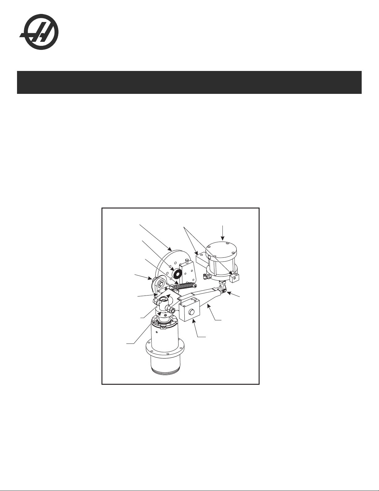
DT-1 - Spindle - Tool Clamp System - Rocker Arm - Removal
1. Jog the Z-Axis down to the bottom of travel. If there is a tool in the spindle, remove it.
2. Remove the C-clip from the clevis pin through the access hole. Pull the clevis pin out from the other
side.
NOTE: Some early assemblies may not include the access hole. In this case, use a
dental pick or similar tool to reach in and work the C-clip off of the pin.
Air Cylinder Clevis Access Example
3. Unhook the tension spring from the rocker arm.
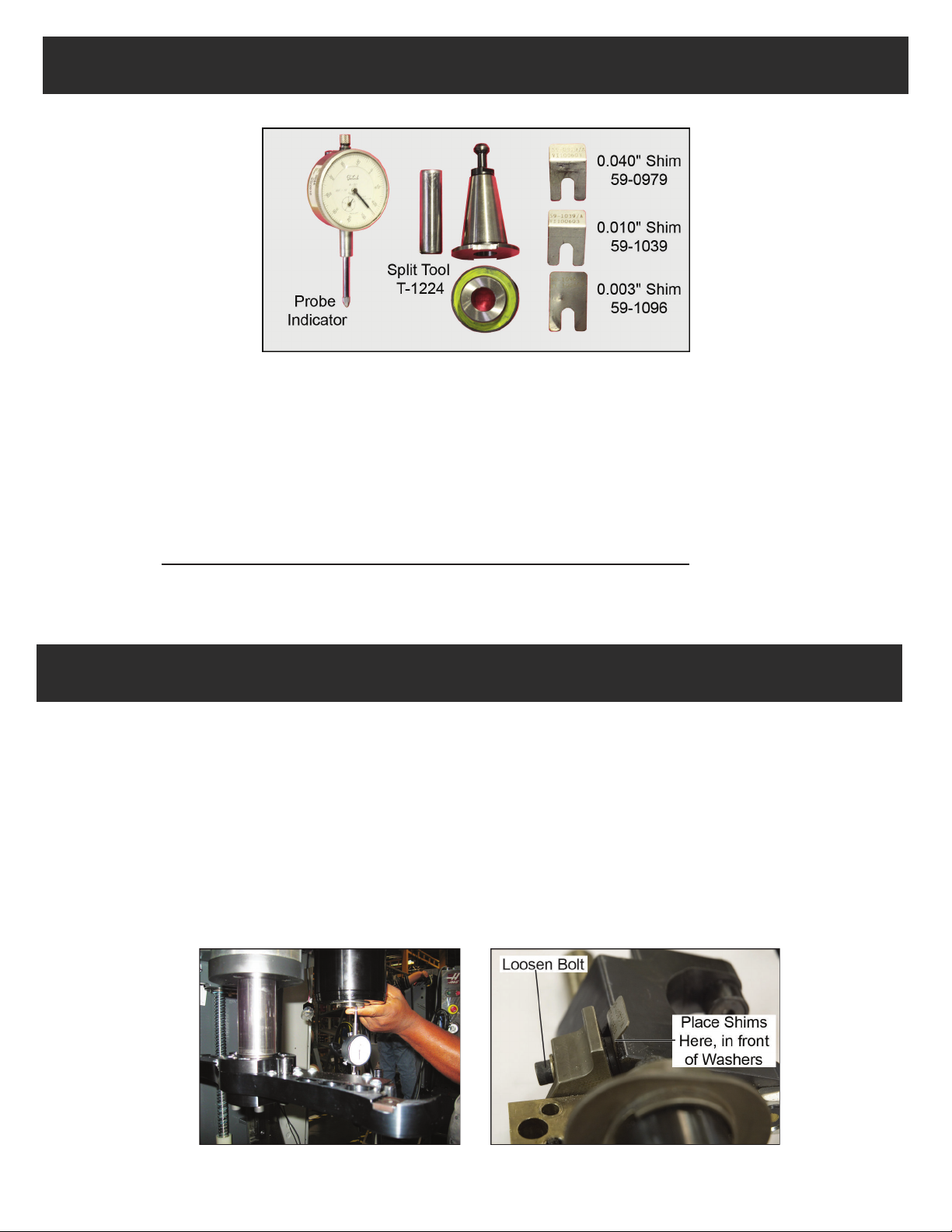
4. Remove the four fasteners from each of the pivot blocks at the front of the rocker arm assembly. Use a
1/4-20 screw to remove the dowel from each block. If the dowel is difficult to remove, use some washers
to space the screw out from the surface of the pivot block, then tighten the bolt to loosen the dowel.
5. At this point, the entire rocker arm assembly is loose, and can be worked out of the spindle head cast-
ing. Take care to prevent the right-side pivot block from dropping—the block and manual release arm can
be disassembled from the shaft to ease removal.
DT-1 - Spindle - Tool Clamp System - Rocker Arm - Installation
1. Assemble the left-hand, two-part pivot block to the rocker arm shaft with the front two screws in the
block (there is insufficient clearance to install them when the block is in place). Work this assembly into
place and secure the pivot block.
2. Slide the manual release arm onto the shaft and into its notch in the rocker arm.
3. Install the wave washer to the shaft. Slide the right-hand pivot block onto the shaft with the front two
screws in the block (there is insufficient clearance to install them when the block is in place).
NOTE: The right-hand pivot block has a specific top and bottom; do not install it upside
down. Identify the top of the block by the larger dowel pin locator hole that al-
lows the dowel to enter easily. The lower hole is close-fitting to the dowel.
4. Secure both pivot blocks with four screws each, then install the dowel pins, making sure the pins are
threaded-end up.
5. Reinstall the tension spring.
6. Reconnect the manual release arm to the air cylinder clevis. Replace the clevis pin and C-clip.
© Copyright 2015 by Haas Automation, Inc. No unauthorized reproduction.
Page 2 of 5

7. With the rocker arm reinstalled, automatic push-out, manual push-out, and rocker arm/release guide
clearance must be checked and adjusted. Refer to the “Adjustments” section.
NOTE: If the rocker arm cam follower roller has been replaced with a larger roller as
part of this service, it may be necessary to grind a path on the outside of the
tool changer cambox to provide clearance. Carefully verify clearance along
Z-axis travel. Interference with the cam follower during operation may lead to
dropped tools and spindle damage.
DT-1 - Spindle - Tool Clamp System - Air Cylinder - Replacement
1. Remove the clevis pin from the end of the air cylinder shaft. Access the pin and its retaining C-clips
through the hole in the spindle head casting (see photo in the previous section).
2. Remove the retainer block from each side of the air cylinder, then remove the air cylinder from the as-
sembly.
3. Install the air cylinder following the removal instructions in reverse order. Once the cylinder is in place, it
must be adjusted for correct operation. See the “Adjustments” section for details.
DT-1 - Spindle - Tool Clamp System - Drawbar Cam - Replacement
1. Jog the Z-axis to put the spindle motor fan in line with the cam, then press Emergency Stop.
2. Remove the spindle motor fan. The cam is accessible through this opening.
3. Remove the screws holding the cam, then carefully remove the cam from the shaft. You can use (4)
1/4-20 screws as jacking bolts to ease removal.
4. Lightly grease the cam shaft.
5. Line up the locator pin on the cambox with the locator hole in the cam and carefully press the cam onto
the shaft. Secure with (7) 3/8-16 x 0.75" screws torqued to 30 ft-lbs.
© Copyright 2015 by Haas Automation, Inc. No unauthorized reproduction.
Page 3 of 5

DT-1 - Spindle - Tool Clamp System - Push-Out Adjustment - Manual
Tools Required
Also required: magnetic base, feeler gauges
1. Place the split tool in the spindle.
2. Indicate the ground surface of the split tool and zero the indicator.
3. Push up on the split tool to keep it from dropping and press Tool Release. The drawbar will push the
split tool out of the spindle.
4. Check the indicator. The tool should be pushed out 0.030". If the pushout varies from this value, adjust
the air cylinder clevis position in or out until the correct pushout is achieved.
NOTE: Each 180° rotation of the clevis adjusts pushout by approximately 0.010". If
an exact pushout of 0.030" cannot be achieved, adjust pushout to the closest
possible value over 0.030". For example, if pushout can only be adjusted to
0.025" or 0.035", adjust it to 0.035"
DT-1 - Spindle - Tool Clamp System - Push-Out Adjustment - Automatic
This adjusts tool push-out when tool release is controlled by the drawbar cam during tool changes.
1. Place the split tool in the spindle.
2. Set rapids to 5% and press ATC FWD to bring the spindle to tool change position. Press Emergency
Stop as soon as the spindle orients to tool change position and the carousel stops moving.
3. Indicate the ground face of the split tool and zero the indicator. Carefully move the indicator and base
away from the split tool (without disturbing the current indicator setting).
4. Make the tool changer axis visible (Parameter 462 bit 18), then jog it in the negative direction until the
split tool is fully released.
Measuring tool push-out Rocker Arm Shim Placement
© Copyright 2015 by Haas Automation, Inc. No unauthorized reproduction.
Page 4 of 5

5. Try to insert the split tool back into the spindle taper. Hold the tool in place while sliding the dial indica-
tor back under the split tool and measure push-out. This should be 0.030"; if it is not, correct pushout by
adding or removing shims.
6. To add or remove shims, loosen the connecting bolt in the rocker arm assembly (see photo above).
Add or remove shims as needed. Shims provide pushout adjustment at a 1:2 ratio; that is, adding a
0.010" shim will increase pushout by 0.020".
NOTE: Install shims forward of the spherical washers in the assembly. Shims should
not interfere with the washers nesting.
7. Retighten the connecting bolt and recheck tool pushout. If still not correct, repeat the shimming proce-
dure to add or remove shims until push-out is equal to 0.030".
8. Reset the tool changer axis to invisible.
Adjusting Rocker Arm / Release Guide Gap
1. Use a feeler gauge or shim to check the gap between the rocker arm cam followers (two rollers) and
the release guide. This distance should be 0.040".
2. To correct this distance, adjust the rocker arm retract bolt (found on the rear of the rocker arm, under
the shim retention bolt) up or down and secure with the jam nut.
3. Recheck the gap and make adjustments as necessary until the gap measures 0.040".
Beginning at 5% rapids, command and observe a tool change. If the change completes successfully,
repeat the test at 25%, then 50%, then 100% rapids, checking each time that the tool is transferred
smoothly between the pocket and spindle.
TESTING
© Copyright 2015 by Haas Automation, Inc. No unauthorized reproduction.
Page 5 of 5
Table of contents
Other Haas Industrial Equipment manuals

Haas
Haas Automatic Pallet Changer User manual

Haas
Haas TSC-300/1K Guide

Haas
Haas Bar Feeder User manual

Haas
Haas TR Series User manual

Haas
Haas Bar Feeder User manual

Haas
Haas EC-400 Installation instructions

Haas
Haas MDC-500 User manual

Haas
Haas SL-20 User manual

Haas
Haas HSF-325 User manual

Haas
Haas ATT-4 User manual
Popular Industrial Equipment manuals by other brands

MR
MR VACUTAP VR I HD-Ex Installation and commissioning instructions

ITW
ITW Simco-Ion Pinner Series Installation and operating instruction

Alphacool
Alphacool HF D5 Top instruction manual

Aerotech
Aerotech ECO225LM Hardware manual

IKA
IKA Big Squid operating instructions

TE Connectivity
TE Connectivity 1871696-1 instruction sheet