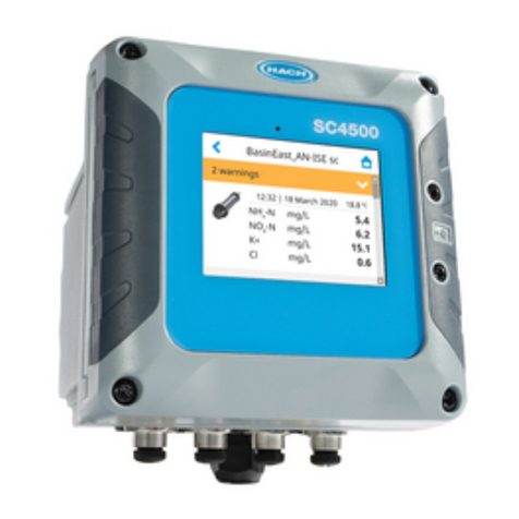
Hach SC4500 User manual

DOC273.52.90750
SC4500 network, HCNB
10/2021, Edition 1
User Instructions


Table of Contents
Section 1 General information............................................................................ 3
1.1 Safety information................................................................................................. 3
1.1.1 Use of hazard information.......................................................................... 3
1.1.2 Precautionary labels................................................................................... 3
1.2 Intended use......................................................................................................... 4
1.3 Product overview.................................................................................................. 4
Section 2 Installation............................................................................................... 4
2.1 LAN connection.................................................................................................... 5
2.2 WiFi network connection....................................................................................... 6
2.3 Cellular network connection.................................................................................. 6
2.3.1 Configuration with Hach Cellular (Telenor) SIM......................................... 7
2.3.2 Configuration with customer supplied SIM................................................. 7
Section 3 Hach Controller Network Bus configuration............................ 7
3.1 HCNB automatic configuration............................................................................. 8
3.2 HCNB view topology list....................................................................................... 8
3.3 HCNB—View statistics......................................................................................... 9
Section 4 Claros configuration........................................................................... 9
Section 5 Network topologies............................................................................. 9
5.1 HCNB through a customer network (LAN only).................................................. 10
5.2 HCNB through a customer network (wired chaining)......................................... 12
5.3 HCNB through a customer network (LAN + WiFi).............................................. 14
5.4 HCNB through embedded LAN server (not Claros compatible)......................... 16
5.5 Claros and HCNB through cellular connection with internet sharing.................. 18
1

Table of Contents
2

Section 1 General information
In no event will the manufacturer be liable for direct, indirect, special, incidental or consequential
damages resulting from any defect or omission in this manual. The manufacturer reserves the right to
make changes in this manual and the products it describes at any time, without notice or obligation.
Revised editions are found on the manufacturer’s website.
1.1 Safety information
The manufacturer is not responsible for any damages due to misapplication or misuse of this product
including, without limitation, direct, incidental and consequential damages, and disclaims such
damages to the full extent permitted under applicable law. The user is soley responsible to identify
critical application risks and install appropriate mechanisms to protect processes during a possible
equipment malfunction.
Please read this entire manual before unpacking, setting up or operating this equipment. Pay
attention to all danger and caution statements. Failure to do so could result in serious injury to the
operator or damage to the equipment.
Make sure that the protection provided by this equipment is not impaired. Do not use or install this
equipment in any manner other than that specified in this manual.
1.1.1 Use of hazard information
D A N G E R
Indicates a potentially or imminently hazardous situation which, if not avoided, will result in death or
serious injury.
WARNING
Indicates a potentially or imminently hazardous situation which, if not avoided, could result in death
or serious injury.
CAUTION
Indicates a potentially hazardous situation that may result in minor or moderate injury.
N O T I C E
Indicates a situation which, if not avoided, may cause damage to the instrument. Information that
requires special emphasis.
1.1.2 Precautionary labels
Read all labels and tags attached to the instrument. Personal injury or damage to the instrument
could occur if not observed. A symbol on the instrument is referenced in the manual with a
precautionary statement.
This is the safety alert symbol. Obey all safety messages that follow this symbol to avoid
potential injury. If on the instrument, refer to the instruction manual for operation or safety
information.
This symbol indicates that a risk of electrical shock and/or electrocution exists.
English 3

This symbol indicates the presence of devices sensitive to Electro-static Discharge (ESD)
and indicates that care must be taken to prevent damage with the equipment.
Electrical equipment marked with this symbol may not be disposed of in European
domestic or public disposal systems. Return old or end-of-life equipment to the
manufacturer for disposal at no charge to the user.
1.2 Intended use
These instructions are intended for use by persons who will integrate Claros enabled controllers,
possibly with a customer network, which is compatible with industrial Ethernet-based infrastructures
and topologies for real-time data sharing.
1.3 Product overview
Use the Hach Controller Network Bus (HCNB) to make a network that is compatible with industrial
Ethernet-based infrastructures and topologies for real-time data sharing. HCNB is a bi-directional
communications protocol used to connect Claros controllers and RTC modules. There is no master
hierarchy in HCNB. All of the controllers and devices on the network have the same function level.
HCNB is compatible with internet sharing. One controller connected to Claros can share the internet
connection with other controllers connected to the same network.
This manual is for SC4500 controllers, but HCNB applies to SC1500, SC4200c and
SC4500 controllers.
Section 2 Installation
Note: Refer to the documentation supplied with the controller for complete installation instructions.
Ethernet LAN or WiFi connectivity is necessary to connect the controller to a HCNB. An Ethernet
LAN or WiFi interface is used to connect all of the devices to the same local network. As an
alternative, controllers can be connected together without a local network.
When configured, the user has access to other controllers or devices in the network and can share
the controller resources. The output of the controller is configured with local and remote sensors and
is attached to the PLC (Programmable Logic Controller). For example, the user can set a sensor
measurement to an analog output from a sensor connected to a different controller at the facility. If
the user moves the sensor to a different controller, the HCNB automatically finds the sensor and
updates the network topology.
Note: With some of the HCNB settings, it is necessary to do a controller restart.
Make sure that the controller connects to the network through LAN or WiFi. The controller has two
Ethernet ports for a Ethernet LAN1 connection. Remove the connector cap to access the connector.
Refer to Figure 1. As an alternative, use the optional USB box for a WiFi wireless connection.
Note: Ethernet and wireless connection can be mixed in the same network topology.
Make all of the necessary wiring connections. Refer to the documentation supplied with the
controller.
1. Connect a maximum of five controllers with a LAN cable or the optional USB box WiFi to the
network.
2. If necessary, make all of the PLC wiring connections.
1Dependent on controller configuration. A color code identifies the connectors. The LAN
connectors are green. The EtherNet/IP or PROFINET connectors are yellow. The Digital SC
sensor connectors are black.
4 English

Figure 1 Controller Ethernet ports options
1 No Ethernet ports (LAN configuration: none) 5 LAN Ethernet connector (LAN configuration:
mix IEP)
2 Digital SC connectors 6 Industrial Ethernet protocol connector (LAN
configuration: mix IEP)
3 Controller 7 Industrial Ethernet protocol connectors (LAN
configuration: IEP only)
4 LAN Ethernet connectors (LAN configuration:
split or chaining)
Note: LAN = LAN Ethernet connector. IEP = Industrial Ethernet protocol connector.
2.1 LAN connection
The controller is supplied with two Ethernet connectors based on the controller configuration.
Regardless of the supplied controller, the user must configure the Ethernet ports to the applicable
option.
Note: An Ethernet port upgrade may be necessary based on the controller configuration. Refer to the
documentation supplied with the upgrade kit.
1. Use a user-supplied Ethernet cable (M12 to RJ45) to connect the controller to a device with
internet connection. Refer to Installation on page 4.
2. Push the main menu icon, then select Controller > Connectivity > LAN > Ethernet ports.
3. Enter the settings.
Option Description
None The controller does not have Ethernet ports or the Ethernet ports are not configured.
The controller is supplied with the option None by default.
Note: When the controller configuration is set back to the factory settings, all of the LAN
connection settings are lost and the Ethernet ports are set back to None.
Chaining The two Ethernet ports are configured for LAN connectivity. When selected, the LAN
port configuration setting shows on the LAN menu. The two Ethernet ports have the
same port configuration. Select this option to share the internet connection with
other controllers (daisy chain topology) or to connect the controller to Claros and
HCNB through the Ethernet cable.
English 5

Option Description
Split One Ethernet port is configured for LAN connectivity and the other Ethernet port is
configured for a separate LAN or Modbus TCP. When selected, the Lan port
1 configuration and Lan port 2 configuration settings show on the LAN menu. The
two Ethernet ports have different port configurations. Select the Split option to have
different controller connections to Claros and fieldbus (Modbus TCP or HCNB).
Mix IEP One Ethernet port is configured for LAN connectivity and the other Ethernet port is
configured for IEP2. When selected, the LAN port configuration setting shows on the
LAN menu. Select this option to use port 1 for LAN connectivity and port 2 for IEP
(compatible with EtherNet/IP or PROFINET star topology).
IEP only The two Ethernet ports are configured for IEP. The two ports are used for
EtherNet/IP or PROFINET with chain, ring or star topology.
4. Push SAVE.
5. When applicable, select LAN port configuration. Enter the settings as follows:
a. If the customer network supports Dynamic Host Configuration Protocol (DHCP), set the option
to on (default) to get an IP address automatically. The display shows the MAC address of the
selected port.
b. If the customer network does not support DHCP, set the option to off and complete the
settings with IP addresses supplied by the network administrator. Enter the correct settings
based on the network topology: IP address, Netmask, Default gateway and DNS address.
c. When Chaining is selected, the LAN server option shows on the LAN port configuration menu.
Set the LAN server to on to share the internet connection with other controllers through LAN
connectivity.
6. Select APPLY.
2.2 WiFi network connection
An external USB box WiFi with a WiFi adapter is necessary to connect the controller to a WiFi
network. Refer to the documentation supplied with the USB box WiFi for more information about the
WiFi installation. Follow all WiFi module manufacturer recommendations and guidance.
If the controller connects to the internet with a WiFi network, do the steps that follow:
1. Push the main menu icon, then select Controller > Connectivity > Wi-Fi.
2. Set the Wi-Fi connectivity button to on. A list of available access points shows.
3. Select Network to set the applicable WiFi access point. If necessary, enter the correct credentials.
The WiFi connectivity currently accepts the authentication methods that follows: User name and
Wi-Fi password.
a. WEP: Not recommended. The WEP authentication method has low security.
b. WPA2 Personal / PSK: Standard authentication. Enter the Wi-Fi passwordto access the
network.
c. WPA2 Enterprise: Authentication for enterprise networks. Enter the enterprise credentials,
User name andWi-Fi password, to access the network.
4. Select APPLY.
2.3 Cellular network connection
Note: Only for Claros connection.
The external USB box cellular is necessary to connect the controller to a mobile network. Refer to the
documentation supplied with the USB box cellular for installation instructions.
2Based on the controller configuration. Make sure that a PROFINET or EtherNet/IP module is
installed in the controller.
6 English

2.3.1 Configuration with Hach Cellular (Telenor) SIM
If the controller connects to the internet with the factory installed SIM card and the default Hach data
plan (Telenor), do the steps that follow:
1. Push the main menu icon, then select Controller > Connectivity > Cellular.
2. Set the Cellular connectivity button to on.
3. Select APPLY.
Note: Make sure that the SIM card is not locked. If necessary, use the SIM PIN setting to enter the SIM card
PIN.
4. After a maximum of 5 minutes, examine the signal strength that shows on the display. The cloud
icon shows a correct connection.
2.3.2 Configuration with customer supplied SIM
To change the SIM card and connect the controller to the internet with a cellular network through a
customer supplied data plan, do the steps that follow:
1. Install a user-supplied Micro SIM card. Refer to the documentation supplied with the USB box
cellular for more information about the cellular network installation.
Note: Follow all the cellular manufacturer recommendations and guidance.
2. Push the main menu icon, then select Controller > Connectivity > Cellular.
3. Make sure that the Cellular connectivity button is set to on.
4. Enter the settings.
Option Description
Provider Sets the Provider name (Access Point Name). Select Telenor (NA/Verizon
network) for the default settings or Other to set a provider.
APN Shows the provider name. When Other is selected on the Provider setting,
enters the name of the provider.
SIM PIN SIM card PIN
User name User name
Password User password
Internet sharing Set to on to share the internet connection with other controllers
5. Select APPLY and wait until a confirmation message shows on the display.
6. After a maximum of 5 minutes, examine the signal strength that shows on the display. The cloud
icon shows a correct connection.
Section 3 Hach Controller Network Bus configuration
The HCNB applies to Claros and non-Claros controllers, but all of the controllers must connect to
HCNB.
Make sure that the controller connects to the network through a LAN or WiFi. Refer to the
documentation supplied with the controller. To configure the controller to use the HCNB, do the steps
that follow:
1. Push the main menu icon, then select Controller > Connectivity > HCNB.
2. Set the HCNB button to on. The controller automatically sets the default parameters for Port,
Interface and Auto detection.
Note: When the HCNB option is enabled, the controllers in the same network are automatically found.
• Set the HCNB button to off to disable HCNB functionality.
English 7

• Set the HCNB button to on to enable HCNB functionality.
3. Push APPLY.
When HCNB is set to on or off, the controller must be restarted.
3.1 HCNB automatic configuration
HCNB uses the standard mDNS protocol to automatically find all of the controllers connected to the
network segment. The mDNS standard supplies network traffic on UDP port 5353. The Auto
detection setting must be disabled to use a different port.
The manufacturer recommends the Auto detection configuration and TCP port 5445 for HCNB.
1. Push the main menu icon, then select Controller > Connectivity > HCNB.
2. Select one of the options that follow:
Note: The settings that follow can only be changed if HCNB is set to off.
Option Description
Port Sets the Ethernet port number for HCNB communication. The port number must
be the same on each controller of the HCNB network. Range from 1024 to 65535
(Default: 5445). Make sure that the network port is not blocked in the Ethernet
network.
Interface Sets the Ethernet interface for HCNB communication. Options:
•ALL (default)—The controller uses WiFi and LAN interfaces for the HCNB.
•LAN—The controller uses only a LAN Ethernet interface for the HCNB.
•WIFI—The controller uses only a WiFi interface for the HCNB.
Auto
detection
Sets the button to on to automatically find all of the devices on the network.
ON (default)—The controller uses the mDNS protocol to automatically find all
devices in the same network segment. mDNS uses UDP port 5353. Make sure
that port 5353 is not blocked in the Ethernet network.
OFF—Auto detection is disabled. No other controllers or devices can be found
and the controller cannot be found by other controllers. The configuration of
HCNB topology must be done manually.
3. Push APPLY.
3.2 HCNB view topology list
The Topology list menu shows all of the controller in the network.
Controller type, controller serial number, SC devices and serial number of the connected controller
show for each device. SC device description and SC device serial number show for the SC device.
8 English

1. Push the main menu icon, then select Controller > Connectivity > HCNB.
2. Select Topology list.
Option Description
Topology List Shows a list with all of the controllers with which the controller communicates
successfully. Shows the sensors connected to each controller.
• Static controllers (future option, currently not available)—Shows the
controllers and sensors manually added with the Topology configuration
option.
• Auto detected controllers—Shows the controllers and sensors automatically
found on the HCNB.
3. Push APPLY.
3.3 HCNB—View statistics
The Statistic menu shows information about the data flow in the network.
1. Push the main menu icon, then select Controller > Connectivity > HCNB. Then, select
Statistic.
2. Select an option.
Option Description
Received Shows the number of packages received in the HCNB.
Transmitted Shows the number of packages transmitted in the HCNB.
3. Push APPLY.
Section 4 Claros configuration
Claros is a web-based suite of solutions that mixes instrument, data and process management.
Mobile Sensor Management (MSM) is part of Claros. MSM lets the user see the measurements and
instrument condition anytime, anywhere on a web-enabled device. MSM shows upcoming
maintenance tasks and gives simple maintenance instructions. Based on the controller configuration,
the controller can connect to Claros to use MSM. Make sure that the controller is connected to the
internet with LAN, Wi-Fi or cellular network.
When the controller connects to the internet with a cellular network, the controller can share the
internet connection with other controllers in the HCNB.
Configure Claros on the controller as follows:
1. Configure internet connection. Refer to the controller documentation.
2. Push the main menu icon, then select Controller > Connectivity > Claros. Set to on.
3. Add the controller to the user Claros account. On a web-enabled device open Claros and follow
the instructions on the screen.
Section 5 Network topologies
The topologies that follow are applicable to the SC4500 network configuration.
English 9

5.1 HCNB through a customer network (LAN only)
Claros is optional. Refer to Claros configuration on page 9 to enable Claros.
Note: Make sure to accurately follow the hardware connection and the configuration of the topology.
Note: If some preliminary settings in the Connectivity menu were changed, it is recommended to go back to the
factory settings. Refer to the controller user manual.
• All of the controllers connect to the same network segment.
• All of the controllers connect to the HCNB.
• Controller 1 and 2 connects to the HCNB through LAN and optionally connects to Claros.
• Controller 3 connects to the HCNB through LAN and connects to a PLC through Industrial
Ethernet protocols, Profibus DP or a mA output.
1 Controller 1, SC4500 4 PLC (refer to the documentation supplied
with the controller, Profinet module and
EtherNet/IP module to configure the PLC)
2 Controller 2, SC4500 5 IEP connection, Profibus DP, or 4-20 mA
connection
3 Controller 3, SC4500 6 Ethernet switch3
1. Set the Controller 1 configuration as follows:
Note: Make sure to connect the Ethernet LAN cable to LAN port 1.
a. To connect to Claros (optional), push the main menu icon, then select Controller >
Connectivity > Claros. Set to on.
b. Push the main menu icon, then select Controller > Connectivity > LAN > Ethernet ports.
Select Chaining.
c. Go to Controller > Connectivity > HCNB > HCNB. Make sure that HCNB is set to Off.
d. Select Controller > Connectivity > HCNB > Interface. Select ALL.
e. Select Controller > Connectivity > HCNB > Auto detection. Select On.
3If Internet is available on the Ethernet switch, Claros can be set to on and off.
10 English

f. Select Controller > Connectivity > HCNB > HCNB. Select On. Push OK to restart the
controller.
Note: Wait until the controller restarts. Do not touch the display or go to other menus or an error message
will show.
2. Set the Controller 2 configuration the same as Controller 1.
3. Set The Controller 3 configuration as follows:
Note: Make sure to connect the Ethernet LAN cable to LAN port 1 and industrial Ethernet cable to IEP port 1.
a. Push the main menu icon, then select Controller > Connectivity > LAN > Ethernet ports.
Select Split or Mix IEP.
b. Go to Controller > Connectivity > HCNB > HCNB. Make sure that HCNB is set to Off.
c. Select Controller > Connectivity > HCNB > Interface. Select ALL.
d. Select Controller > Connectivity > HCNB > Auto detection. Select On.
e. Select Controller > Connectivity > HCNB > HCNB. Select On. Push OK to restart the
controller.
Note: Wait until the controller restarts. Do not touch the display or go to other menus or an error message
will show.
English 11

5.2 HCNB through a customer network (wired chaining)
Claros is optional. Refer to Claros configuration on page 9 to enable Claros.
Note: Make sure to accurately follow the hardware connection and the configuration of the topology.
Note: If some preliminary settings in the Connectivity menu were changed, it is recommended to go back to the
factory settings. Refer to the controller user manual.
• All of the controllers connect to the same network segment.
• All of the controllers connect to the HCNB.
• Controller 1 and 2 connect to the HCNB through LAN and to Claros (optional).
• Controller 3 connects to the HCNB through LAN and connects to a PLC through Industrial
Ethernet protocols, Profibus DP or a mA output.
1 Controller 1, SC4500 4 PLC (refer to the documentation supplied
with the controller, PROFINET module and
EtherNet/IP module to configure the PLC)
2 Controller 2, SC4500 5 IEP connection, Profibus DP, or 4-20 mA
connection
3 Controller 3, SC4500 6 Ethernet switch4
1. Set the Controller 1 configuration as follows:
a. To connect to Claros (optional), push the main menu icon, then select Controller >
Connectivity > Claros. Set to on.
b. Push the main menu icon, then select Controller > Connectivty > LAN > Ethernet ports.
Select Chaining.
c. Select Controller > Connectivity > LAN > Ethernet ports > LAN port configuration > LAN
server. Select Turn On.
d. Go to Controller > Connectivity > HCNB > HCNB. Make sure that HCNB is set to Off.
e. Select Controller > Connectivity > HCNB > Interface. Select ALL.
f. Select Controller > Connectivity > HCNB > Auto detection. Select On.
4If Internet is available on the Ethernet switch, Claros can be set to on and off.
12 English

g. Select Controller > Connectivity > HCNB > HCNB. Select On. Push OK to restart the
controller.
Note: Wait until the controller restarts. Do not touch the display or go to other menus or an error message
will show.
2. Set the Controller 2 configuration as follows:
a. To connect to Claros (optional), push the main menu icon, then select Controller >
Connectivity > Claros. Set to on.
b. Push the main menu icon, then select Controller > Connectivity > LAN > Ethernet ports.
Select Chaining.
c. Go to Controller > Connectivity > HCNB > HCNB. Make sure that HCNB is set to Off.
d. Select Controller > Connectivity > HCNB > Interface. Select ALL.
e. Select Controller > Connectivity > HCNB > Auto detection. Select On.
f. Select Controller > Connectivity > HCNB > HCNB. Select On. Push OK to restart the
controller.
Note: Wait until the controller restarts. Do not touch the display or go to other menus or an error message
will show.
3. Set the Controller 3 configuration as follows:
Note: Make sure to connect the Ethernet LAN cable to LAN port 1 and industrial Ethernet cable to IEP port 1.
a. Push the main menu icon, then select Controller > Connectivity > LAN > Ethernet ports.
Select Split or Mix IEP.
b. Go to Controller > Connectivity > HCNB > HCNB. Make sure that HCNB is set to Off.
c. Select Controller > Connectivity > HCNB > Interface. Select ALL.
d. Select Controller > Connectivity > HCNB > Auto detection. Select On.
e. Select Controller > Connectivity > HCNB > HCNB. Select On. Push OK to restart the
controller.
Note: Wait until the controller restarts. Do not touch the display or go to other menus or an error message
will show.
English 13

5.3 HCNB through a customer network (LAN + WiFi)
Claros is optional. Refer to Claros configuration on page 9 to enable Claros.
Note: Make sure to accurately follow the hardware connection and the configuration of the topology.
Note: If some preliminary settings in the Connectivity menu were changed, it is recommended to go back to the
factory settings. Refer to the controller user manual.
• All of the controllers connect to the same network segment. The Ethernet switch and the WiFi
access point share the same network.
• All of the controllers connect to the HCNB.
• Controller 1 and 2 connect to the network through WiFi. and to Claros (optional).
• Controller 3 connects to the HCNB through LAN and connects to a PLC through Industrial
Ethernet protocols, Profibus DP or a mA output.
1 Wi-Fi USB box 5 PLC (refer to the documentation supplied
with the controller, Profinet module and
EtherNet/IP module to configure the PLC)
2 Controller 1, SC4500 6 IEP connection, Profibus DP, or 4-20 mA
connection
3 Controller 2, SC4500 7 Ethernet switch5
4 Controller 3, SC4500
1. Set the Controller 1 configuration as follows:
a. To connect to Claros (optional), push the main menu icon, then select Controller >
Connectivity > Claros. Set to on.
b. Push the main menu icon, then select Controller > Connectivity > LAN > Ethernet ports.
Select None.
c. Go to Controller > Connectivity > HCNB > HCNB. Make sure that HCNB is set to Off.
5If Internet is available on the Ethernet switch, Claros can be set to on and off.
14 English

d. Select Controller > Connectivity > HCNB > Interface. Select Wi-Fi.
e. Select Controller > Connectivity > Wi-Fi > Wi-Fi connectiviy. Select On. Refer to WiFi
network connection on page 6 to configure the Wi-Fi connection.
f. Select Controller > Connectivity > HCNB > HCNB. Select On. Push OK to restart the
controller.
Note: Wait until the controller restarts. Do not touch the display or go to other menus or an error message
will show.
2. Set The Controller 2 configuration the same as Controller 1.
3. Set the Controller 3 configuration as follows:
Note: Make sure to connect the Ethernet LAN cable to LAN port 1 and industrial Ethernet cable to IEP port 1.
a. Push the main menu icon, then select Controller > Connectivity > LAN > Ethernet ports.
Select Split or Mix IEP.
b. Go to Controller > Connectivity > HCNB > HCNB. Make sure that HCNB is set to Off.
c. Select Controller > Connectivity > HCNB > Interface. Select ALL.
d. Select Controller > Connectivity > HCNB > Auto detection. Select On.
e. Select Controller > Connectivity > HCNB > HCNB. Select On. Push OK to restart the
controller.
Note: Wait until the controller restarts. Do not touch the display or go to other menus or an error message
will show.
English 15

5.4 HCNB through embedded LAN server (not Claros compatible)
Note: Make sure to accurately follow the hardware connection and the configuration of the topology.
Note: If some preliminary settings in the Connectivity menu were changed, it is recommended to go back to the
factory settings. Refer to the controller user manual.
• All of the controllers connect to the same network segment.
• All of the controllers connect to the HCNB.
• Controller 1 is the LAN server and connects to the HCNB through this LAN.
• Controller 2 connects to the HCNB through a LAN.
• Controller 3 connects to the HCNB through LAN and connects to a PLC through Industrial
Ethernet protocols, Profibus DP or a mA output.
1 Controller 1, SC4500 4 PLC (refer to the documentation supplied
with the controller, PROFINET module and
EtherNet/IP module to configure the PLC)
2 Controller 2, SC4500 5 IEP connection, Profibus DP, or 4-20 mA
connection
3 Controller 3, SC4500
1. Set the Controller 1 configuration as follows:
a. Push the main menu icon, then select Controller > Connectivity > LAN > Ethernet ports.
Select Chaining.
b. Select Controller > Connectivity > LAN > LAN port configuration > LAN Server. Select
On.
c. Go to Controller > Connectivity > HCNB > HCNB. Make sure that HCNB is set to Off.
d. Select Controller > Connectivity > HCNB > Interface. Select ALL.
e. Select Controller > Connectivity > HCNB > Auto detection. Select On.
f. Select Controller > Connectivity > HCNB > HCNB. Select On. Push OK to restart the
controller.
Note: Wait until the controller restarts. Do not touch the display or go to other menus or an error message
will show.
2. Set the Controller 2 configuration as follows:
a. Push the main menu icon, then select Controller > Connectivity > LAN > Ethernet ports.
Select Chaining.
b. Go to Controller > Connectivity > HCNB > HCNB. Make sure that HCNB is set to Off.
c. Select Controller > Connectivity > HCNB > Interface. Select ALL.
16 English

d. Select Controller > Connectivity > HCNB > Auto detection. Select On.
e. Select Controller > Connectivity > HCNB > HCNB. Select On. Push OK to restart the
controller.
Note: Wait until the controller restarts. Do not touch the display or go to other menus or an error message
will show.
3. Set the Controller 3 configuration as follows:
Note: Make sure to connect the Ethernet LAN cable to LAN port 1 and industrial Ethernet cable to IEP port 1.
a. Push the main menu icon, then select Controller > Connectivity > LAN > Ethernet ports.
Select Split.
b. Go to Controller > Connectivity > HCNB > HCNB. Make sure that HCNB is set to Off.
c. Select Controller > Connectivity > HCNB > Interface. Select ALL.
d. Select Controller > Connectivity > HCNB > Auto detection. Select On.
e. Select Controller > Connectivity > HCNB > HCNB. Select On. Push OK to restart the
controller.
Note: Wait until the controller restarts. Do not touch the display or go to other menus or an error message
will show.
English 17

5.5 Claros and HCNB through cellular connection with internet sharing
Note: Make sure to accurately follow the hardware connection and the configuration of the topology.
Note: If some preliminary settings in the Connectivity menu were changed, it is recommended to go back to the
factory settings. Refer to the controller user manual.
• All of the controllers connect to the same network segment.
• All of the controllers connect to the HCNB.
• Controller 1 connects to Claros using cellular and shares the connection through LAN. Controller
1 also connects to the HCNB through this LAN.
• Controller 2 connects to Claros and HCNB through LAN.
• Controller 3 connects to Claros and HCNB though a LAN and connects to a PLC through Industrial
Ethernet protocols, Profibus DP or a mA output.
1 Cellular USB box 4 Controller 3, SC4500
2 Controller 1, SC4500 5 PLC (refer to the documentation supplied
with the controller, PROFINET module and
EtherNet/IP module to configure the PLC)
3 Controller 2, SC4500 6 IEP connection, Profibus DP, or 4-20 mA
connection
1. Set the Controller 1 configuration as follows:
a. Push the main menu icon, then select Controller > Connectivity > Claros. Set to on.
b. Select Controller > Connectivity > LAN > Ethernet ports. Select Chaining.
c. Select Controller > Connectivity > Cellular. To configure the cellular network refer to
Cellular network connection on page 6.
d. Select Controller > Connectivity > Cellular > Internet sharing. Set to On (default: Off)
e. Go to Controller > Connectivity > HCNB > HCNB. Make sure that HCNB is set to Off.
f. Select Controller > Connectivity > HCNB > Interface. Select ALL.
g. Select Controller > Connectivity > HCNB > Auto detection. Select On.
18 English
Other manuals for SC4500
9
Table of contents
Other Hach Controllers manuals